Landau-Zener interferometry with superconducting qubits
Abstract
Quantum-mechanical systems having two discrete energy levels are ubiquitous in nature. For crossing energy levels, depending on how fast they approach each other, there is a possibility of a transition between them. This phenomenon is known as Landau-Zener tunneling [1, 2, 3, 4, 5] and it forms the physical basis of the Zener diode, for example. The traditional treatment of the Landau-Zener tunneling, however, ignores quantum-mechanical interference. Here we report an observation of phase-sensitive interference between consecutive Landau-Zener tunneling attempts in an artificial two-level system formed by a Cooper-pair-box qubit [6, 7]. We interpret the experiment in terms of a multi-pass analog to the well-known optical Mach-Zehnder interferometer. In our case, the beam splitting occurs by Landau-Zener tunneling at the charge degeneracy, while the arms of the Mach-Zehnder interferometer in energy space are represented by the ground and excited state. Our Landau-Zener interferometer can be used as a high-resolution detector for phase and charge owing to interferometric sensitivity-enhancement. The findings also demonstrate new methods for qubit manipulations.
Low Temperature Laboratory, Helsinki University of Technology, FIN-02015 HUT, Finland
Landau Institute for Theoretical Physics, Kosygin st. 2, 119334 Moscow, Russia
Landau-Zener (LZ) tunneling is a celebrated quantum-mechanical phenomenon, taking place at the intersection of two energy levels that repel each other due to a weak interaction [8]. The LZ theory, developed in the early 1930’s in the context of slow atomic collisions [1, 2, 3] and spin dynamics in time-dependent fields [4], demonstrated that transitions are possible between two approaching levels as a control parameter is swept across the point of minimum energy separation. The LZ tunneling is often used as a tool for determining level separations, for example, in molecular NMR [9]. The probability of a Landau-Zener tunneling transition is given by [1, 2, 3, 4]:
| (1) |
where denotes the variation rate of the energy spacing for noninteracting levels, and is the minimal energy gap.
Yet for quantum-mechanical systems, more fundamental is the transition amplitude, which allows one to describe interference. As two colliding atoms approach each other, their electronic levels may cross. The probability amplitudes evolve along either of the two potential curves and may interfere, when the levels cross again after the collision. The wave-function phase accumulated between the incoming and outgoing traversals varies with the collision energy giving rise to Stueckelberg oscillations, observed in atomic systems [10], in the populations. Typically, however, the phase is large and rapidly varies with energy, which allows one to average over these fast oscillations [5, 3], neglecting the interference.
Recently, quantum coherence in mesoscopic Josephson tunnel junctions has been investigated extensively [6, 11, 12], since they might provide a realistic platform for quantum-information processing. In these artificial quantum systems, energy scales can easily be tuned into a range feasible for study of fundamental phenomena. We used a system of such mesoscopic junctions to obtain the first evidence of quantum interference associated to Landau-Zener tunneling in non-atomic systems.
We used a charge qubit based on a Cooper-pair box (CPB) that we turned into an analog of the optical Mach-Zehnder interferometer. In this device, a beam is split into two partial waves, which interfere after a single passage through the system. In our case, the LZ tunneling provides the mechanism of the beam splitting and occurs when the gate charge of the Cooper-pair box is swept across the degeneracy (Fig. 1). The split beams follow the ground and excited states of the CPB and recombine at the subsequent degeneracy point. We find a collection of different types of interference patterns which can be described using the basic principles of Mach-Zehnder interferometers. Our interferometric observations are made possible by the non-invasive character of our dispersive measurement method [13, 14].
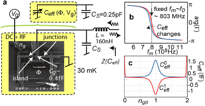
Our superconducting Mach-Zehnder interferometer is made using a single-Cooper-pair transistor (SCPT) embedded into a small superconducting loop (Fig. 2). An SCPT consists of a mesoscopic island having capacitance , two small Josephson junctions, and of a nearby gate electrode used to polarize the island with the (reduced) gate charge . The island has the charging energy Kelvin, and the junctions have the generally unequal Josephson energies , where quantifies the asymmetry. With , SCPT Hamiltonian is then . Here, the number of extra electron charges on the island is the quantum conjugate variable to , where is the superconducting phase on the island. The SCPT is then equivalent to a Cooper-pair box, but with an effective Josephson energy of tunable by the superconducting phase across the two junctions, . Here, is the magnetic flux quantum. Diagonalization of the Hamiltonian leads to energy bands (supplementary information on bands: see Ref. [15]).
When , the Hamiltonian is conveniently written in the eigenbasis of the charge operator , taking only two charge states into account. Then the Hamiltonian of the CPB becomes
| (2) |
| (3) |
where and .
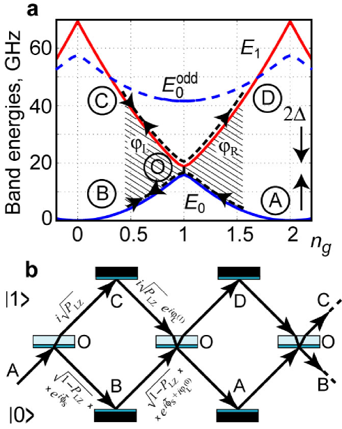
We display here the Hamiltonian both in the matrix form (2) and in the spin form, Eq. (3). The asymmetry in Josephson energies would limit the minimum value for the off-diagonal coupling . The eigenvalues and are the two lowest bands as illustrated by Fig. 1a. By and , we denote the corresponding wave functions.
We analyze the level crossing process using the energy diagram in Fig. 1a. As is lowered and then increased (similar to the interatomic distance during a collision), the system can follow either of two possible paths: AOCOD and AOBOD. The probability to follow either path is a product of two independent events: for making a transition and for staying on the same level, which gives the total transition probability
| (4) |
In this treatment interference between tunnel attempts has been neglected.
Subsequent LZ tunneling events with time interval can interfere, provided phase coherence is preserved and these events do not overlap [16, 17], . Here, the time of an LZ-tunneling event [18] is . In charge qubits, it is easy to make where the coherence time is with and corresponding to the relaxation and dephasing time, respectively. For example, by taking GHz and GHz per 1 ns, we obtain ns, which is well within experimental reach. The interference of consecutive tunneling attempts can be viewed as two partial waves, describing the propagation along either the lowest band or the first excited band. This is similar to an optical Mach-Zehnder interferometer as illustrated in Fig. 1b.
Away from the crossing region, the eigenstates and accumulate the dynamical phase
| (5) |
In addition, each pass of the level crossing results in an LZ event with probability amplitudes given by (cf. Fig. 1b) [16, 17]:
| (6) |
Here, , where the Stokes phase depends on the adiabaticity parameter (cf. Eq. (1)). In the adiabatic limit, , but in the sudden limit, .
Let us assume a fast gate charge sweep of the form , where the constant level means that the sweep is in general offset from the crossing point. One cycle of continuous driving in our CPB takes the system twice through the crossing point and involves two dynamical phase shifts and , on the left and right sides. For a single cycle, we add the amplitudes along the two branches in Fig. 1b, to find the probability of reaching the point D:
| (7) |
Clearly, the maximum transition probability is reached when the total phase is a multiple of . Under continuous driving, one obtains a multi-pass Mach-Zehnder model. In this case it can be shown that the maximum population of (constructive interference) is reached when both dynamical phases satisfy the condition mentioned above,
| (8) |
For example, in the adiabatic limit, have to be odd multiples of . The resonance conditions in Eq. (8) are seen overlayed in Figs. 3 and 4 (see below) as the black solid and dashed lines.
Our experimental scheme is illustrated in Fig. 2. The measurement signal tracks the time average, under a strong LZ drive, of the Josephson capacitance , probed at MHz (see Methods). In the first approximation, the energy here can be taken as the average energy stored in the qubit: , where the band energies are weighted by their average populations and , respectively. Thus, we have
| (9) |
In this way, however, we neglect all the relaxation phenomena that take place on time scales : If the relaxation rate then changes in have to be taken into account in the response. As will be seen below this is in fact crucial in understanding our experimental results.
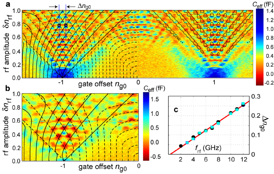
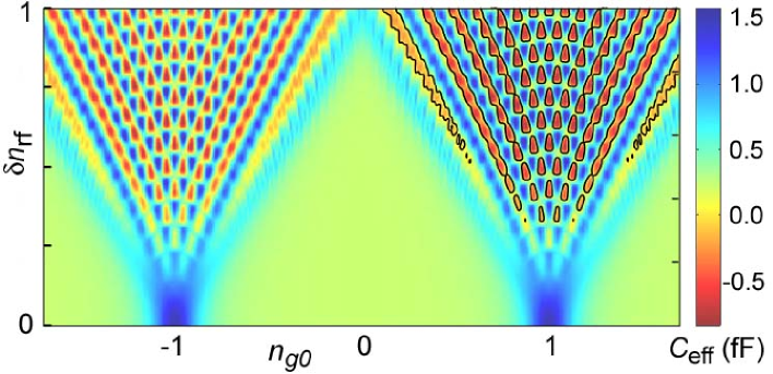
We have made extensive scans of the reflection coefficient of a CPB by varying the LZ drive frequency GHz, and its amplitude electrons, as well as the bias and . The Josephson capacitance deduced from the phase shift of the reflected wave at GHz when changing and is illustrated in Fig. 3. We observe a clear interference pattern whose main characteristics agree with those expected for coherent LZ tunneling: 1) There is an onset of the interference speckles with a distinct value for where the rf drive just reaches the avoided crossing, linearly dependent on the AC drive amplitude; 2) The density of the dots is proportional to in the direction of as well as , 3) The central part of the interference patterns displays the curved dot rows, in a similar fashion as in the overlayed patterns, 4) the pattern loses its contrast at a certain value towards lowering drive frequency, here at GHz. Note also that there are destructive interference dots at high drives, where the qubit remains basically on the lowest level (cf. the ”coherent destruction of tunneling” [19]).
The periodicity in is clearly at low levels of rf-excitation. At excitations on the order of , there is an appearance of a shifted, additional pattern, which makes the signal almost -periodic. The origin of these odd sectors can be understood by looking at the energy levels displayed in Fig. 1. When the rf-drive brings the system past a crossing point of and , it becomes energetically favorable to enter an odd particle-number state, resulting in a shift by in the interference pattern. The odd states appear to be rather stable [20], and the contrast of the ”odd sectors” is almost as strong (see Fig. 3).
According to Eq. (8), the phase difference,
| (10) |
is a multiple of at resonances, implying the location of the population peaks on the lines of fixed gate bias with spacings (we approximated the dynamical phase by that for non-interacting levels). This linear dependence of the spacings on frequency is illustrated in Fig. 3c. The fitted line yields K, which is about 25 % higher than we obtained from the rf-spectroscopy [14].
As usual, interference effects are prone to decoherence and our interferograms are suitable for studying dephasing and relaxation in qubits as proposed by Shytov et al. [7]. The suppression of interference in our data at low is due to the loss of phase memory over a single LZ cycle. Indeed, phase fluctuations suppress the contrast of oscillations in Eq. (7) (see Ref. [16] for a more detailed analysis). This way, we find a quick estimate, averaged over , for the coherence time of our qubit ns.
To account for decoherence in a detailed manner, we solved the phenomenological Bloch equations [21, 22] which describe the dynamics of the magnetization of a pseudospin- (a two-level system):
| (11) |
Here, the pseudomagnetic field is given by Eq. (3). The parameters and describe the relaxation of the -component of magnetization towards equilibrium and the relaxation of transverse magnetization to zero, respectively. Assuming that decoherence is dominated by charge noise, we write
| (12) |
| (13) |
Here, the angle describes the dependence on the gate bias, and the voltage fluctuations are involved via . For Ohmic dissipation, where the coefficient characterizes both the bath and its coupling to the qubit: . For our sample, due to strong coupling to the environment via the high gate capacitance and parasitic capacitance in the resonator inductance.
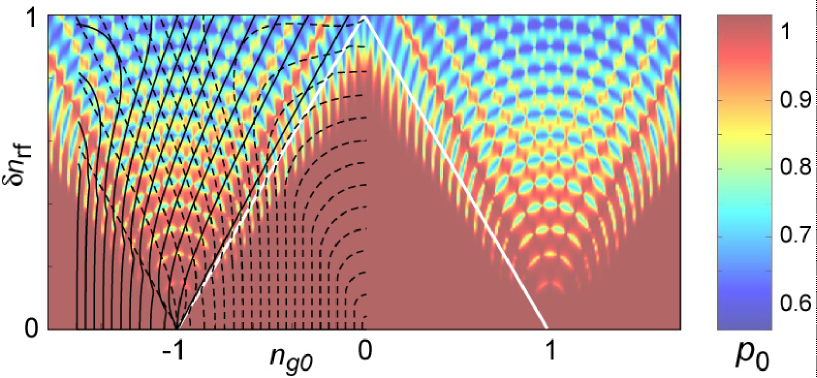
The results of the simulations for a strong driving are illustrated in Fig. 4. It displays the population of the ground state on the vs. plane for Ohmic bath with . The variation of the level population agrees well to the overlayed interference pattern obtained using the Mach-Zehnder model, except for the regions near the edges (the inclined white lines in Fig. 4). The additional structure in this region is a signature of multiphoton transitions: Under the condition of the -photon resonance () the effective coupling in the pseudospin rotating frame is [23] , and from the stationary solution of the Bloch equations (with gate-independent relaxation terms) we find the population response [24] . The Bessel functions describe the onset of the resonance as well as the interference pattern at higher drives. This expression indicates that destructive interference occurs at amplitudes corresponding to zeros of the Bessel functions, and that the destructive interference spots are sharper, in accordance with the data.
The range of the capacitance variation on the lower level, –1.5 fF, deduced from the data measured without the LZ drive, are in accordance [14] with the ground band curvature, shown in Fig. 2c. As the maximum population on the upper level can only reach 50 %, the weighted average, Eq. (9), should always be larger than 0.2 fF (see Fig. 2). Clearly, there are regions in Fig. 3 where the response looks stronger. Hence, instead of Eq. (9), we have to calculate a time average , whose magnitude can be substantially increased by relaxation phenomena.
Assuming very fast relaxation, i.e., with the populations tracking the instantaneous AC gate charge , we find a capacitance of good uniformity, in a similar manner to that of the measured interference patterns. However, at reasonable values of parameter , the swing of the capacitance is too large indicating that the assumption of instantaneous relaxation is too strong.
With a finite relaxation , we have calculated the spin dynamics having a weak measurement signal of amplitude on. Then, we can use the linear-response theory to extract the capacitance. We calculate the time-dependent expectation value for the effective charge , where , and the density matrix is expressed in the energy eigenbasis. From we pick up the quadrature components, and , at the measurement frequency. Using the definition of impedance, we may solve for the capacitance . The resulting capacitance at GHz is illustrated in Fig. 5. The full swing of the capacitance over the vs. plane is very sensitive to the parameter . The values and were taken for the calculation in order to match the measured pattern. This corresponds at the degeneracy point to ns which is close to the estimates obtained both from the oscillation contrast, and microwave spectroscopy. The calculation reproduces the major features of the measured interferograms: 1) The spacing of the dots, 2) the size of the capacitance swing, 3) the global uniformity of the pattern, and 4) minima and maxima on separate arcs (rather than on the same arc).
Similarly as optical interferometry played a central role in the development of ”photon” physics [25], solid-state quantum interferometry [26] may find many applications. We propose to apply the LZ interferometry for sensitive detection of phase and charge utilizing mesoscopic Josephson circuits [27, 28, 14], where it brings about a significant increase in sensitivity. Indeed, the LZ interferometer can be viewed as integrating phase amplifier for the superconductor phase across the device. The interferometer transforms tiny changes of (or magnetic flux ) into a huge modulation of the wave-function phase by basically integrating the hatched area in Fig. 1 [29], but at the expense of reduced measurement strength. Eventually, it amounts at least to -fold increase in detector sensitivity, with significantly reduced disturbance due to the measurement signal. Another possibility would be to separate the LZ modulation drive to the other quadrature, namely , and measure charge. The modulation in the off-diagonal components would result in slightly different interference phenomena, as predicted recently by Hänggi and coworkers [30].
The coherent Landau-Zener process observed in this work also serves as a suitable method, intermediate between the two existing schemes, for manipulations of superconducting qubits. Thus far, qubit operations have been carried out either using lengthy rf-pulses which induce Rabi oscillations, or by sub-nanosecond ”hard” pulses [6] shaped rectangularly in time. The LZ manipulation would offer an ultra-short clock period ns similarly to hard pulses, but would be more precise due to basically single-frequency drive, and also technologically simpler.
Acknowledgements
Fruitful discussions with R. Fazio, M. Feigelman, T. Heikkilä, F. Hekking, and M. Paalanen are gratefully acknowledged. This work was financially supported by the Academy of Finland, by the National Technology Agency, and by the Vaisala Foundation of the Finnish Academy of Science and Letters.
Methods
Our investigations of the LZ tunneling are based on measuring the quantum (or ”Josephson”) capacitance of a CPB [14, 31]. This capacitance is related to the curvature of band [32, 33], similar to the effective mass of an electron in a crystal:
| (14) |
The difference in the Josephson capacitance for allows us to determine the state of the CPB.
We perform low-dissipation microwave reflection measurements [27, 28, 15] on a series resonator in which the box effective capacitance, Eq. (14), is a part of the total capacitance . The resonator is formed by a surface mount inductor of nH. With a stray capacitance of fF due to the fairly big lumped resonator, the resonant frequency is MHz and the quality factor is limited by the external . When varies, the phase of the reflected signal changes, which is measured by the reflection coefficient . Here, is the resonator impedance as marked in Fig. 2. Since we work rather far from matching conditions, the magnitude of the reflection coefficient remains always close to one. The variation in due to modulation in is up to 40∘ in our measurements, corresponding to a shift of resonance frequency MHz. In addition to band pass filtering, we used two circulators at 20 mK to prevent the back-action noise of our cryogenic low-noise amplifier from reaching the qubit. In all the measurements, the probing signal was continuously applied.
References
- [1] Landau, L. Zur Theorie der Energieübertragung II. Phys. Z. Sowjet. 2, 46 (1932).
- [2] Zener, C. Non-adiabatic crossing of energy levels. Proc. R. Soc. (London) A 137, 696 (1932).
- [3] Stueckelberg, E. C. G. Theorie der unelastischen Stösse zwischen Atomen. Helv. Phys. Acta 5, 369 (1932).
- [4] Majorana, E. Atomi orientati in campo magnetico variable. Nuovo Cimento 9, 45 (1932).
- [5] Landau, L. Zur Theorie der Energieübertragung bei Stössen. Phys. Z. Sowjet. 1, 88 (1932).
- [6] Nakamura, Y., Pashkin, Yu. A. & Tsai, J. S. Coherent control of macroscopic quantum states in a single-Cooper-pair box. Nature 398, 786 (1999).
- [7] Shytov, A. V., Ivanov, D. A. & Feigel’man, M. V. Landau-Zener interferometry for qubits. Eur. Phys. J. B 36, 263 (2003). See also Shevchenko, S.N., Kiyko, A.S., Omelyanchouk, A.N., & Krech, W. Dynamic behaviour of Josephson-junction qubits: crossover between Rabi oscillations and Landau-Zener transitions, J. Low Temp. Phys. 31, 752 (2005) (cond-mat/0412588).
- [8] von Neumann, J. & Wigner, E. Über das Verhalten von Eigenwerten bei adiabatischen Prozessen. Phys. Z. 30, 467 (1929).
- [9] Wernsdorfer, W. & Sessoli, R. Quantum phase interference and parity effects in magnetic molecular clusters. Science 284, 133 (1999).
- [10] Coffey, D., Lorents, D. C. & Smith, F. T. Collision Spectroscopy. II. Inelastic Scattering of He+ by Ne. Phys. Rev. 187, 201 (1969).
- [11] Makhlin, Yu., Schön, G. & Shnirman, A. Quantum-state engineering with Josephson-junction devices. Rev. Mod. Phys. 73, 357 (2001).
- [12] Izmalkov, A. et al. Observation of macroscopic Landau-Zener transitions in a superconducting device. Europhys. Lett. 65, 844 (2004).
- [13] Wallraff, A. et al. Strong coupling of a single photon to a superconducting qubit using circuit quantum electrodynamics. Nature 431, 162 (2005).
- [14] Sillanpää, M. A. et al. Direct observation of Josephson capacitance. Phys. Rev. Lett. accepted (2005).
- [15] Sillanpää, M. A. Quantum device applications of mesoscopic superconductivity. Ph.D. thesis, Helsinki University of Technology (2005). URL http://lib.tkk.fi/Diss/2005/isbn9512275686/.
- [16] Shimshoni, E. & Gefen, Y. Onset of dissipation in Zener dynamics: Relaxation versus dephasing. Ann. Phys. 210, 16 (1991).
- [17] Kayanuma, Y. Stokes phase and geometrical phase in a driven two-level system. Phys. Rev. A 55, R2495 (1997).
- [18] Mullen, K., Ben-Jacob, E., Gefen, Y. & Schuss, Z. Time of Zener tunneling. Phys. Rev. Lett. 62, 2543 (1989).
- [19] Grossmann, F., Dittrich, T., Jung, P. & Hänggi, P. Coherent destruction of tunneling. Phys. Rev. Lett. 67, 516 (1991).
- [20] Aumentado, J., Keller, M. W., Martinis, J. M. & Devoret, M. H. Nonequilibrium quasiparticles and periodicity in single-Cooper-pair transistors. Phys. Rev. Lett. 92, 066802 (2004).
- [21] Bloch, F. Nuclear induction. Phys. Rev. 70, 460 (1946). See also Bloch, F. Generalized theory of relaxation, Phys. Rev. 105, 1206 (1957).
- [22] Makhlin, Yu., Schön, G. & Shnirman, A. Dissipation in Josephson qubits. In Fazio, R., Gantmakher, V. F. & Imry, Y. (eds.) New Directions in Mesoscopic Physics (Towards Nanoscience), 197 (Kluwer, 2003). Cond-mat/0309049.
- [23] Henry, C. H. & Lang, D. V. Nonradiative capture and recombination by multiphoton emission in GaAs anf GaP. Phys. Rev. B 15, 989 (1977). Lopez-Castillo, J.-M., Filali-Mouhim, A., & Jay-Gerin, J.P., Periodic motion around the crossing point in a two-level system, J. Chem. Phys. 97, 1905 (1992).
- [24] Abragam, A. The principles of nuclear magnetism (Clarendon, Oxford, 1961).
- [25] Zeilinger, A., Weihs, G., Jennewein, T. & Aspelmeyer, M. Happy centenary, photon. Nature 433, 230 (2005).
- [26] Ji, Y. et al. An electronic Mach-Zehnder interferometer. Nature 422, 415 (2003).
- [27] Sillanpää, M. A., Roschier, L. & Hakonen, P. Inductive single-electron transistor. Phys. Rev. Lett. 93, 066805 (2004).
- [28] Roschier, L., Sillanpää, M. & Hakonen, P. Quantum capacitive phase detector. Phys. Rev. B 71, 024530 (2005).
- [29] Gorelik, L. Y., Lundin, N. I., Shumeiko, V. S., Shekhter, R. I. & Jonson, M. Superconducting single-mode contact as a microwave-activated quantum interferometer. Phys. Rev. Lett. 81, 2538 (1998).
- [30] Wubs, M., Saito, K., Kohler, S., Kayanuma, Y. & Hänggi, P. Landau-Zener transitions in qubits controlled by electromagnetic fields. cond-mat/0508156 (2005).
- [31] Duty, T. et al. Observation of quantum capacitance in the Cooper-pair transistor. cond-mat/0503531 (2005).
- [32] Widom, A. et al. The Josephson pendulum as a nonlinear capacitor. J. Low Temp. Phys. 57, 651 (1984).
- [33] Averin, D. V., Zorin, A. B. & Likharev, K. K. Bloch oscillations in small-size Josephson junctions. Sov. Phys. JETP 61, 407 (1985).