Surface Roughness and Hydrodynamic Boundary Conditions
Abstract
We report results of investigations of a high-speed drainage of thin aqueous films squeezed between randomly nanorough surfaces. A significant decrease in hydrodynamic resistance force as compared with predicted by Taylor’s equation is observed. However, this reduction in force does not represents the slippage. The measured force is exactly the same as that between equivalent smooth surfaces obeying no-slip boundary conditions, but located at the intermediate position between peaks and valleys of asperities. The shift in hydrodynamic thickness is shown to be independent on the separation and/or shear rate. Our results disagree with previous literature data reporting very large and shear-dependent boundary slip for similar systems.
pacs:
82.70.Dd, 83.80.Qr, 82.70.-yIt has been recently well-recognized that the classical no-slip boundary condition Lamb (1932), which has been applied for more than a hundred years to model macroscopic experiments, is often not applicable at the submicro- and especially nanoscale. Although the no-slip assumption seems to be valid for molecularly smooth hydrophilic surfaces down to a contact Chan and Horn (1995); Israelachvili (1986); Klein et al. (1993); Vinogradova and Yakubov (2003); Cottin-Bizonne et al. (2005), it is now clear that this is not so for the majority of other systems. The changes in hydrodynamic behavior are caused by an impact of interfacial phenomena, first of all hydrophobicity and roughness, on the flow. A corollary from this is that a theoretical description based on the no-slip condition has to be corrected even for simple liquids. What, however, still remains a subject of hot debates is that how to correct the flow near the interface, and what would be the amplitude of these corrections.
The simplest and the most popular way to model the flow is to use a slip-flow approximation de Gennes (1985), which assumes that the slip velocity at the solid wall is proportional to the shear stress, and the proportionality constant is the so-called slip length. Such an assumption was justified theoretically for smooth hydrophobic surfaces Vinogradova (1999); Barrat and Bocquet (1999); Andrienko et al. (2003) and was confirmed by recent surface force apparatus (SFA) Baudry et al. (2001); Cottin-Bizonne et al. (2005) and atomic force microscope (AFM) Vinogradova and Yakubov (2003) dynamic force experiments. Despite some remaining controversies in the data and amount of slip (cf. Granick et al. (2003)), a concept of a hydrophobic slippage is now widely accepted.
For rough surfaces a situation is much less clear both on the theoretical and experimental sides. One point of view is that roughness decreases the degree of slippage Granick et al. (2003); Zhu and Granick (2002); Pit et al. (2000), unless the surface is highly hydrophobic, so that trapped nanobubbles are formed to accelerate the flow Vinogradova et al. (1995); Cottin-Bizonne et al. (2003). An opposite conclusion is that roughness generates extremely large slip Bonaccurso et al. (2003).
We believe our letter entirely clarifies the situation with flow past rough surfaces, highlights reasons for existing controversies, and resolves apparent paradoxes.
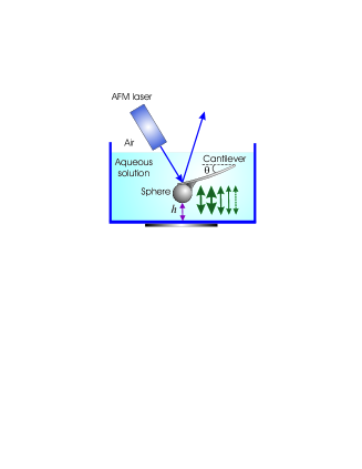
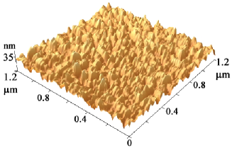
We use a specially designed home-made AFM-related setup Ecke et al. (2001); Vinogradova et al. (2001); Yakubov et al. (2000) to perform dynamic force experiments on a nanoscale (Fig. 1). Glass spheres of radius m (Duke Scientific, PaloAlto, CA) were attached with UV glue on the top of the rectangular tipless cantilever (length m, width m, spring constants N/m). The spheres were then coated with a gold layer (50 nm) using a layer of chromiun (3 nm) to promote adhesion. For the planar substrate we used a silicon wafer coated with a gold layer (50 nm). Both surfaces were then treated with a 1 mM solution of 11-amino-undecane thiol (SH-(CH2)11-NH2) for 24 hrs to produce a chemically bound SAM. The advancing and receding water contact angle on the thiolated planar surfaces were measured with a commercial setup (Data Physics, Germany), and were found to be ()∘ and ()∘, respectively. These values are close to those for surfaces used in Craig et al. (2001). Imaging of thiolated surfaces with a regular AFM tip revealed the root-mean-square roughness over a is in the range 10-11 nm for a sphere and 0.5-0.8 nm for a plane. The maximum peak-to-valley difference is less than 45 nm for a sphere (Fig. 2) and less than 2.5 nm for a plane. This (smooth against rough) geometry of configuration allows one to avoid large scatter in data at separations of the order of or smaller than the roughness size. Such a scatter would be inavoidable for two rough surfaces (depending whether the rough sphere is falling on a tip or in a valley of a rough plane). Cantilevers were then fixed in a holder with the variable tilt angle, and the intermediate position with the angle was chosen. A planar substrate was placed onto the bottom of a Teflon cuvette, which was filled with 1mM NaCl (99.99%, Aldrich) aqueous solutions. Water for solutions was prepared using a commercial Milli-Q system containing ion-exchange and charcoal stages. The deionized water had a conductivity less than S/m and was filtered at 0.22 m. To measure force-versus-position curves the cuvette was moved towards the particle with a 12 m range piezoelectric translator (Physik Instrumente, Germany). This translator was equipped with integrated capacitance position sensors, which allows to avoid any creep and hysteresis and provided the position with an accuracy of 1 nm in closed-loop operation. During the movement the deflection of the cantilever was measured with an optical lever technique. Therefore the light of a laser diode (1.5 mW, 670 nm) was focused onto the back of the gold coated cantilever. After reflection by a mirror, the position of the reflected laser spot was measured with a position sensitive device (United Detectors, UK, active area mm2). The total force was calculated by multiplying instantaneous cantilever deflection with the spring constant. The distance between surfaces was calculated by adding the piezo displacement to the deflection of the cantilever, so that corresponds to the contact [of tips of sphere’s asperities with a plane] (see Fig. 1). We stress, that since our plane is smooth, we have no ambiguity in determining this zero of separation.
The AFM force balance incorporates both (concentrated) force on the sphere and the drag on the cantilever Vinogradova and Yakubov (2003) (Fig. 1), so that the total force measured in the AFM dynamic experiment is
| (1) |
where and are the surface and the hydrodynamic forces, correspondingly, acting on a sphere, and is the force due to distributed hydrodynamic drag on the cantilever.
The total force is proportional to the instantaneous deflection of the end of the spring from its equilibrium position multiplied by the spring constant Chan and Horn (1995)
| (2) |
where is the initial separation between surfaces, and is the driving speed of piezo (negative speed corresponds to approach).
The hydrodynamic force between a sphere and a plane can be written as Vinogradova (1995)
| (3) |
where is the dynamic viscosity, is the relative velocity of the surfaces. To finalize the description of we should define the expressions for a correction function , which will be discussed later. Note that when , Eq. 3 transforms to famous Taylor’s formula (which, however, never appeared in any of G.I.Taylor’s publications as discussed in Horn et al. (2000)).
The drag force on a cantilever is given by Vinogradova and Yakubov (2003)
| (4) |
with
| (5) |
where . Here is a constant, which reflects the contribution from the Stokes flow to the cantilever deflection, and represents an adjustable (dimensionless) parameter to the model.
The surface force is assumed to be unaffected by the relative motion of surfaces, and was taken to be the equilibrium force being a function of only . It was obtained from low speed (below 1 m/s) force measurements. At distances larger than 20-25 nm no interaction was detected. In other words, no electrostatic contribution can be seen despite relatively large (9.6 nm) Debye length in 1 mM NaCl solution. This suggests that the surfaces are uncharged. Similar observations have been made before for some other classes of thiols Ederth et al. (1998). The range of the jump distance was always nm. The contribution of contact deformation to the jump distance was estimated using the experimental values for the pull-off force mN/m (with the correction to the hydrodynamic interaction) and the values of Young’s modulus of the UV glue (3 GPa), as it was the softest material in our system. We also ignore the possible plastic flattening of the gold (50 GPa) asperities. For these parameters the central displacement due to a contact deformation is of the order of 0.1 nm, so that it can safely be ignored. We have fitted the experimental results by assuming , taking the Hamaker constant, , as an adjusting parameter. The value J is obtained from fitting and was further used in all calculations.
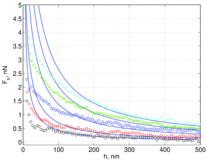
Fig. 3 shows the hydrodynamics resistance force calculated by subtracting and from the total force measured. Theoretical curves obtained by a numerical solution of differential Eq.(1) in the assumption are also included. Note that cantilever contribution was found to be neither small or negligible. The adjusting parameter reflecting Stokes-like flow on a cantilever was about 30-34 for our geometry of configuration and slightly varied from one experiment to another. Measured is much smaller than predicted by Taylor’s theory. The deviations from theory are clearly seen at distances 100-200 nm depending on the driving speed. One can conclude therefore that there is clear impact of roughness on the film drainage.
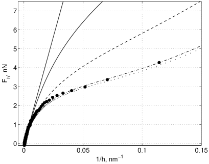
In Fig. 4 the hydrodynamic force measured at driving speed m/s is compared with Taylor’s equation (solid curves). The force is plotted versus the inverse of the surface separation. Note that even Taylor’s equation does not result in a linear plot. This would be expected only at a constant approach velocity, which is not the case due to forces acting on the sphere. However these, caused by decrease of , deviations from linearity are much smaller than required to fit experimental data. The general analytical solution for rough interfaces does not exist in the literature probably since such a problem is outside the scope of a lubrication approximation. Below we analyze some approximate models.
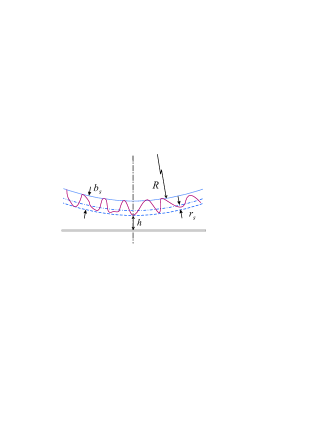
We have calculated the force expected between smooth slippery surfaces. The slip length is assumed to be roughly equal to zero for a sphere and to the height of asperities (as defined in Fig. 2) for a sphere, which is close to its definition. In this case the correction for slippage takes the form Vinogradova (1995)
| (6) |
An improved fit to the data is obtained when slip is permitted (dashed curve in Fig. 4). For this speed of approach the best fit to Eq. 6 was found with nm. Eq. 6 provides an excellent fit at distances larger than 100 nm. However, since data still deviate from theoretical predictions at smaller separations, it is clear that slippage does not necessarily represent the roughness.
Therefore, we further assumed that stick boundary conditions remain valid, but are applied to a surface defined at a distance towards a sphere:
| (7) |
By adjusting the value of we found that the hypothesis of a shift in separation gives a perfect coincidence between data and theoretical predictions (dash-dotted curve in Fig. 4, obtained with nm). We remark and stress that Eq. 7 provides an excellent description of the data even when is much smaller than . [Another point to note is that the values of seem to be slightly larger than would be expected from the AFM imaging, which is likely connected with the fact that the AFM tip has a finite size and cannot go into grooves].
We thus conclude that the description of flow near rough surfaces has to be corrected, but this is not the relaxation of no-slip boundary conditions, but the correction for separation with its shift to larger distances within the asperities size. It has to be stressed that similar ideas were justified theoretically at macroscale for a shear flow along periodically corrugated wall Richardson (1971) and recently for a far-field motion of a sphere towards such a wall Lecoq et al. (2004). They are also consistent with molecular-dynamic simulations on simple model systems Bocquet and Barrat (1994). Here for the first time we provided accurate experimental data showing that the concept can be applied for a randomly rough wall and at the nanoscale, down to a contact. Note that Eq. 7 has not received so far any theoretical justification for short, i.e. of the order of or smaller than the size of asperities, separations. This is probably because this situation escapes from the framework of the lubrication approximation since two length scales of the problem become comparable. The applicability of Eq. 7 at the short distances probably reflects the fact that the height of the roughness elements is much smaller than the sphere radius, so that even when separation is getting small, the plane “sees” many roughness elements at the same time and fluctuations are averaged out. This hypothesis remains the subject for further theoretical work.
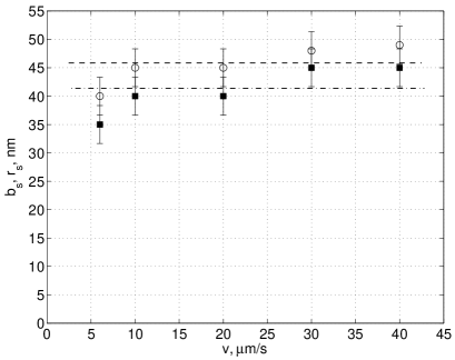
This conclusion remains valid for all driving speeds, and results are summarized in Fig. 5. One can see that remains roughly the same at all speeds, although it shows some weak tendency to increase with the rate of approach. However, this increase is within the error of experimental data, so it remains an open question for future research. The same remarks are true for , which is included for completeness since slip-model is applicable at large separations.
Note that our results clarify the reason for apparently contradictory reports suggesting that roughness increase Pit et al. (2000) and decrease Bonaccurso et al. (2003) the drag force. In our opinion these different conclusions only reflect that in these papers the wall location was defined differently. It follows from our results that if equivalent smooth surface is defined as coinciding with the location of valleys of asperities (which corresponds to experimental techniques used in Pit et al. (2000)), the measured force is larger than expected for an equivalent surface (cf. dotted curve in Fig. 4). If, however, it is defined on the peaks of asperities (experimental techniques used in Bonaccurso et al. (2003)), then the measured force is smaller (cf. dashed curve in Fig. 4). Clearly, both results Pit et al. (2000); Bonaccurso et al. (2003) physically mean that roughness increase the dissipation in the system, and that an equivalent surface is located at the intermediate position. Note, that in Granick et al. (2003), which reports the increase in force with roughness, the equivalent surface is also defined on the peaks of asperities. We do not have any explanation of this result.
Our data and conclusions do not confirm results obtained with similar, but “smooth” surfaces, where shear-rate dependent slippage was detected Craig et al. (2001). In our opinion, the reduction in hydrodynamic resistance force might indicate that their gold-coated thiolated sphere was in reality rougher than expected. Reasons for a shear-dependency could probably be connected with some errors in experimental determination of since the piezotranslator used in Craig et al. (2001), and later in Bonaccurso et al. (2003), is not suitable for highly dynamic force measurements due to its non-linearity. Another reason for a significant rate-dependence is the use of binary mixtures Craig et al. (2001). Clearly, both confinement and shear might lead to their stratification and a formation of a thin low viscosity lubricant layer Andrienko et al. (2003). It is well known and has been proven experimentally Horn et al. (2000) that such a layer leads to rate-dependent phenomena (normally expected only at a very large shear rate Thompson and Troian (1997)) even at low speed. We suspect that this effect of stratification of binary mixture, enhanced by roughness, is responsible for a very large reduction in force observed in Bonaccurso et al. (2003). Finally, we would like to stress that since the force balance represents a differential equation, even small could implicate the results by decreasing , and therefore . The similar remark concern , which cannot be excluded from analysis. Both and are not present in the force balance specified in Craig et al. (2001); Bonaccurso et al. (2003), which might cause further inaccuracy in results.
In summary, by performing high-speed drainage experiment with nanorough hydrophilic surfaces we demonstrate that their interaction is similar to that between equivalent smooth surfaces located at some position between peaks and valleys of asperities. Thus, our results are in favor of no-slip assumptions for a hydrophilic surface valid down to a contact.
This work was supported by a DFG through its priority program “Micro and Nanofluidics” (Vi 243/1-2). We thank E.Bonaccurso, H.J.Butt, and V.S.J.Craig for discussion of details of their experiments, and F.Feuillebois for helpful remarks on the manuscript.
References
- Lamb (1932) H. Lamb, Hydrodynamics (Dover, New York, 1932).
- Chan and Horn (1995) D. Y. C. Chan and R. G. Horn, J. Chem. Phys. 83, 5311 (1995).
- Israelachvili (1986) J. N. Israelachvili, J. Colloid Interface Sci. 110, 263 (1986).
- Klein et al. (1993) J. Klein, Y. Kamiyama, H. Yoshizawa, J. N. Israelachvili, G. H. Fredrickson, P. Pincus, and L. J. Fetters, Macromolecules 26, 5552 (1993).
- Vinogradova and Yakubov (2003) O. I. Vinogradova and G. E. Yakubov, Langmuir 19, 1227 (2003).
- Cottin-Bizonne et al. (2005) C. Cottin-Bizonne, B. Cross, A. Steinberger, and E. Charlaix, Phys. Rev. Lett. 94, 056102 (2005).
- de Gennes (1985) P. G. de Gennes, Rev. Mod. Phys. 57, 827 (1985).
- Vinogradova (1999) O. I. Vinogradova, Int. J. Miner. Process. 56, 31 (1999).
- Barrat and Bocquet (1999) J. L. Barrat and L. Bocquet, Phys. Rev. Lett. 82, 4671 (1999).
- Andrienko et al. (2003) D. Andrienko, B. Dünweg, and O. I. Vinogradova, J. Chem. Phys. 119, 13106 (2003).
- Baudry et al. (2001) J. Baudry, E. Charlaix, A. Tonck, and D. Mazuyer, Langmuir 17, 5232 (2001).
- Granick et al. (2003) S. Granick, Y. Zhu, and H. Lee, Nat. Mater. 2, 221 (2003).
- Zhu and Granick (2002) Y. X. Zhu and S. Granick, Phys. Rev. Lett. 88, 106102 (2002).
- Pit et al. (2000) P. Pit, H. Hervet, and L. Leger, Phys. Rev. Lett. 85, 980 (2000).
- Vinogradova et al. (1995) O. I. Vinogradova, N. F. Bunkin, N. V. Churaev, O. A. Kiseleva, A. V. Lobeyev, and B. W. Ninham, J. Colloid Interface Sci. 173, 443 (1995).
- Cottin-Bizonne et al. (2003) C. Cottin-Bizonne, J. L. Barrat, L. Bocquet, and E. Charlaix, Nat. Mater. 2, 237 (2003).
- Bonaccurso et al. (2003) E. Bonaccurso, H.-J. Butt, and V. S. J. Craig, Phys. Rev. Lett. 90, 144501 (2003).
- Ecke et al. (2001) S. Ecke, R. Raiteri, E. Bonaccurso, C. Reiner, H. J. Deiseroth, and H. J. Butt, Rev. Sci. Instrum. 72, 4164 (2001).
- Vinogradova et al. (2001) O. I. Vinogradova, G. E. Yakubov, and H. J. Butt, J. Chem. Phys. 114, 8124 (2001).
- Yakubov et al. (2000) G. E. Yakubov, H. J. Butt, and O. I. Vinogradova, J. Phys. Chem. B 104, 3407 (2000).
- Craig et al. (2001) V. S. J. Craig, C. Neto, and D. R. M. Williams, Phys. Rev. Lett. 87, 054504 (2001).
- Vinogradova (1995) O. I. Vinogradova, Langmuir 11, 2213 (1995).
- Horn et al. (2000) R. G. Horn, O. I. Vinogradova, M. E. Mackay, and N. Phan-Thien, J. Chem. Phys. 112, 6424 (2000).
- Ederth et al. (1998) T. Ederth, P. Claesson, and B. Liedberg, Langmuir 14, 4782 (1998).
- Richardson (1971) S. Richardson, J. Fluid Mech. 49, 327 (1971).
- Lecoq et al. (2004) N. Lecoq, R. Anthore, B. Cichocki, P. Szymczak, and F. Feuillebois, J. Fluid Mech. 513, 247 (2004).
- Bocquet and Barrat (1994) L. Bocquet and J. L. Barrat, Phys. Rev. E 49, 3079 (1994).
- Thompson and Troian (1997) P. A. Thompson and S. M. Troian, Nature 389, 360 (1997).