Scattering of surface plasmons by one-dimensional periodic nanoindented surfaces
Abstract
In this work, the scattering of surface plasmons by a finite periodic array of one-dimensional grooves is theoretically analyzed by means of a modal expansion technique. We have found that the geometrical parameters of the array can be properly tuned to achieve optimal performance of the structure either as a Bragg reflector or as a converter of surface plasmons into light. In this last case, the emitted light is collimated within a few degrees cone. Importantly, we also show that a small number of indentations in the array are sufficient to fully achieve its functional capabilities.
pacs:
73.20.Mf, 78.67.-n, 41.20.JbSurface plasmons (SPs) are well known for their capabilities for concentrating light in sub-wavelength volumes and guiding light through the surface of a metal Barnes03 . This has recently raised the prospect of SP-based photonic circuits, with length scales much smaller than those currently achieved Ditlbacher02 ; Weeber01 ; Bozhe01 . In order to reach this goal, it is mandatory to know the scattering properties of SPs by simple surface profiles, as pointed out by recent experimental studies Ditlbacher02 ; Devaux03 ; Weeber04 ; JGRivas04 ; Bozhe05 ; Stepajun05 From the theoretical side, this is still an open problem, even after a few seminal works based on the Rayleigh expansion SG98 ; SG99 ; SG05 and the Green’s function dyadic Pince94 ; Sonde . Both these methods require the evaluation of sophisticated scattering functions from which physical insight is not easily inferred.
In this work we present an alternative formalism for calculating the scattering of SPs by indentations perforated on a thick metal film. For that purpose, we have extended to real metals the modal expansion technique previously developed within the perfect conductor approximation (PCA) FJ03 ; JBravo04 , therefore incorporating surface plasmon polaritons into the model. This approach enables us to describe the scattering properties of an arbitrary set of indentations without any restriction over their position or shape. Besides, our method does not require any adjustable parameter, inasmuch as the wavelength-dependent dielectric function of the metal is previously known. In addition to this, it provides a very compact representation of the electromagnetic (EM) fields and simple expressions for the scattering magnitudes, which permits us to extract underlying physical mechanisms much more easily.
Within our theoretical framework, the way of launching SPs onto a set of indentations resembles the back-side illumination employed in some experimental works Devaux03 . We consider a single slit flanked by a set of indentations placed in the output surface of an infinite metallic film of thickness (see Fig.1). Eventually, the distance between the slit and indentations will be taken to be infinity. In this way, the slit merely plays the role of a theorist’s SP-launcher. More precisely speaking, SPs are taken into account by applying surface impedance boundary conditions (SIBC) Jack_book to the metal/dielectric interface along the film surface.
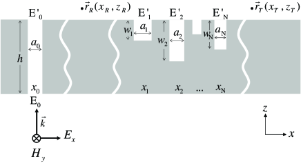
In this work, we consider the simplest case of 1D subwavelength indentations (grooves). Additionally, we impose that the external illumination be uniform along the -axis, so we restrict ourselves to scattering of SPs impinging onto the grooves at normal incidence, where only the fundamental mode inside each groove is relevant. This leads to a set of equations for the modal amplitudes of the electric field at the input and output openings of the slit () and the output openings of the grooves ():
| (1) |
Notice that this set of equations is the same as the one obtained within the PCA JBravo04 . Therefore, its physical meaning remains unchanged, although the expressions are slightly different due to the non-zero impedance at the metal surface: takes into account the back-side illumination on the slit (which must be -polarized in order to excite SPs); the “self-energy” is related to the bouncing back and forth of the EM fields inside indentation . For a groove, , where , being and the depth of the groove; represents the coupling between the two sides of the slit. Finally, is the coupling between modes, reflecting that mode emits radiation that can be collected by mode . More precisely, is the projection onto the wavefields at the openings of indentations and of a scalar Green’s function
| (2) |
As , Eq. (2) transforms into an integral representation of the 0th-order Hankel function of the first kind FJ03 , thus recovering the PCA in the low-energy limit of our approach. Even within the SIBC approximation, we find that the PCA result is still valid for . However, the presence of in Eq.(2) strongly modifies its long-distance behavior. By means of the saddle-point approximation, we have obtained an asymptotic expansion of in the limit where :
| (3) |
with satisfying the SP dispersion relation of a flat metal-dielectric interface within the SIBC, . Therefore, the long distance EM coupling along the surface is due to SPs, even in the presence of absorption. Comparison with the exact result in the optical regime shows that the asymptotic limit is already reached for small distances. For example, in the case of silver at nm, we find that differs from by less than for . It is this knowledge of long-distance EM coupling being mediated by plasmons what allows us to use the system in Fig. 1 for the analysis of SP scattering.
Let us then examine the term in Eq. (1). It can be interpreted as an “slit illumination” impinging on the grooves. Thus, the equation governing the EM fields at the grooves becomes
| (4) |
where is defined to resemble the back-side illumination . The key point is that, according to Eq. (3), corresponds to a SP illumination, modulated by a constant factor that depends on the metal thickness, the intensity of back illumination and the width of the slit. This factor is not relevant for the determination of scattering coefficients and the whole slit can then be treated as a theoretical artifact.
Once the self-consistent are obtained, the calculation of the EM field in all space is straightforward, and therefore both the emittance (which is the fraction of incoming SP energy radiated into vacuum) and its angular distribution. As the EM coupling between the grooves and a distant point on the surface is due to SP, we can also obtain the SP reflection () and transmission () amplitudes:
| (5) |
where is a geometrical coefficient associated to each indentation. Notice that, if absorption is present, and the SP reflected and transmitted currents depend on the points at which the EM are evaluated, reflecting the absorption loss in the flat regions of the metal surface. This suggests that the scattering coefficients should be extracted from the EM fields at points close to the grooves, although in this case it is difficult to separate the diffractive contribution from the one due to SPs. Nevertheless, provided that the grating lengths considered are shorter than the SP absorption length, absorption can be neglected. In what follows, we present the results obtained under such assumption for finite periodic arrays of rectangular grooves, patterned on a Ag film.
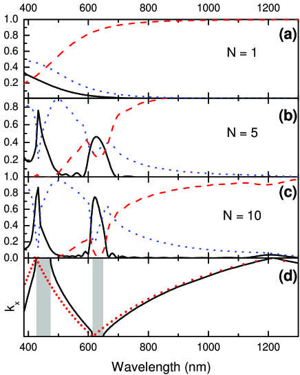
We consider grooves with width nm and depth nm separated by a period of 600 nm, which are typical experimental values. Figures 2(a)-(c) render the calculated reflectance , transmittance and emittance spectra, for increasing values of . For a single groove (top panel), increases with , while both and decrease. This is due to two mechanisms. First, there is a decrease of the relative size of the groove with respect to , which manifests in scaling as . Second, at longer s, the SP wavefield is more extended in the air region and therefore less sensitive to the presence of obstacles at the surface. Panels (b) and (c) show how the addition of more grooves greatly modifies the optical response of the system. As increases, transmission gaps develop, as well as sharp resonances in both and .
In order to gain insight into the origin of this behavior, it is helpful to analyze the EM surface modes of an infinite groove array. This can be readily done by looking for solutions to Eq. (4), imposing both and Bloch’s theorem (i.e. , being the extended surface state wavevector at the given wavelength). The band structure (solid line) for surface modes in a periodic structure with the same geometrical parameters as in (a) to (c) is presented in Fig.2(d), as well as the dispersion relation of SPs in a flat air/silver interface (dots). As expected Kitson96 , band gaps occur with a low- edge given by with , i.e. by the folding of the dispersion relation in a flat surface. On the contrary, the high- edge depends on the geometry of the grooves, as it corresponds to a SP standing wave with maxima at the groove positions. Evidently, spectral regions of low in the finite array coincide with gaps in the band structure. Energy conservation implies a corresponding increase in , but it is not obvious how this increase is divided between these two channels. However, there is a simple argument for the existence of reflection maxima. Let us consider the SP wavefields emitted by two consecutive grooves in the region of reflection. There is an “optical path” phase difference of between these waves. Additionally, there is also a phase difference between emitters that is equal to in the case of a infinite system. But, as previously noted, at the low-wavelength gap edge so the SP wavefields launched by all grooves interfere constructively (notice that they also interfere constructively in the transmission region, but not with the incident field). As is increased away from this condition, the constructive interference is progressively lost, decreases and, for within the gap, increases. If crosses the gap edge, the transmission channel is open, and decreases. Therefore, presents peaks at the high- edges of the gaps, as can be seen in Fig.2. In our opinion, this mechanism can explain the heuristic criterion for optimum mirror efficiency presented in Ref. Weeber04 and may also be at the root of the strong asymmetry in the positions of the reflectance peaks reported in Ref. Bozhe05 .
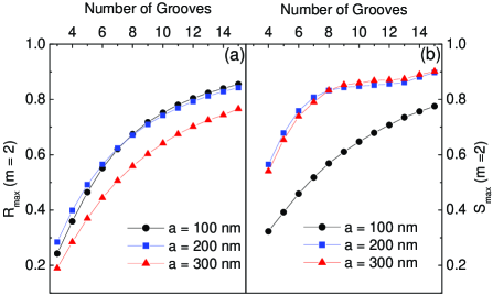
Figure 3 renders the maximum and as a function of the number of grooves in the vicinity of for the same , parameters as in Fig. 2 and increasing values of . Notably, a small number of indentations are sufficient to achieve either a large in-plane reflection or a high emission out of the plane. This rapid saturation is also consistent with Ref. Weeber04 . With respect to the groove width, it is clear that it mainly influences the out-of-plane efficiency of every single scatterer, being more relevant for the vs ratio than for mirror efficiency.
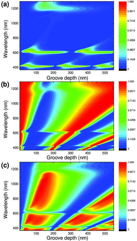
The dependence of the scattering coefficients on groove depth is depicted in Figure 4, for , nm and nm. As can be seen, the maxima of vary weakly on for most ranges of groove depth. Such a weak dependence may be relevant for device design, considering that the control of is often the most difficult point in groove fabrication. However, Figure 4 also shows that for some values of the reflection is very small, when a maximum is expected. Simultaneously, at these groove depths, and . This occurs close to the condition , when the in-plane electric field at the indentations is very small, due to destructive interference of the incident field and the field reflected on the closed end of the groove.
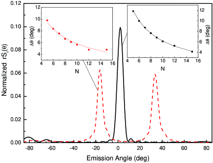
One of the possible applications of finite arrays of indentations lies in their capability to convert SPs into light. Therefore, it is worth studying the directionality properties of the emitted light in the system analyzed throughout this paper. Figure 5 shows the far-field angular distribution of radiation emitted out of plane, evaluated for the two emittance maxima in Fig. 2c ( nm and nm) at the low-energy edges of the gaps labelled, respectively, with and . The distribution corresponding to the gap with (solid curve) is beamed close to the normal. On the contrary, the one coming from the gap with is beamed at higher angles. Notice that, at the condition of maximum , , so the emittance would be normal for even and close to tangent for odd . Inboxes render the FWHM of angular distribution peaks for both curves as a function of the number of grooves. As expected from usual grating theory, it scales as .
To summarize, in this paper we have presented a theoretical framework that can treat the scattering of SPs by a finite array of indentations. With this formalism, we have studied the scattering properties of a sub-wavelength periodic groove array in the visible and near IR ranges. We have found that, associated to the low- edge of the SP band gap, the array behaves as a mirror (up to 80 reflectance) whereas at the high- edge, most of the light carried out by the SP can be converted into collimated light (up to 90). We have also shown that this resonant behavior can be achieved with a small number of indentations (around 10) and it is quite robust with respect to variations in the groove depth.
Financial support by the EU (projects FP6-NMP4-CT-2003-505699 and FP6-2002-IST-507879) and Spanish MEC (contracts MAT2002-01534, MAT2002-00139 and BFM2003-08532-C02-01) is gratefully acknowledged.
References
- (1) See, for example, W. L. Barnes, A. Dereux and T. W. Ebbesen, Nature (London) 424, 824 (2003) and references therein.
- (2) H. Ditlbacher, J. R. Krenn, G. Schider, A. Leitner and F. R. Aussenegg , Appl. Phys. Lett. 81, 1762 (2002).
- (3) J. C. Weeber, J. R. Krenn, A. Dereux, B. Lamprecht, Y. Lacroute and J. P. Goudonnet, Phys. Rev B 64, 045411 (2001).
- (4) S. I. Bozhevolnyi, J. Erland, K. Leosson, P. M. W. Skovgaard and J. M. Hvam, Phys. Rev. Lett. 86, 3008 (2001).
- (5) E. Devaux, T. W. Ebbesen, J. C. Weeber and A. Dereux, Appl. Phys. Lett. 83, 4936 (2003).
- (6) J. C. Weeber, Y. Lacroute, A. Dereux, E Devaux, T. W. Ebbesen, M. U. González and A. L. Baudrion, Phys. Rev B 70, 235406 (2004).
- (7) J. Gómez-Rivas, M. Kuttge, P. Haring Bolivar and H. Kurz, Phys. Rev. Lett. 93, 256804 (2004).
- (8) S. I. Bozhevolny, A. Boltasseva, T. Søndergaard,T. Nikolajsen and K. Leosson, Opt. Comm. 250, 328 (2005).
- (9) A. L. Stepanov, J. R. Krenn, H. Ditlbacher, A. Hohenau, A. Drezet, B. Steinberger, A. Leitner and F. R. Aussenegg, Opt. Lett. 30, 1524 (2005).
- (10) J. A. Sánchez-Gil, Appl. Phys. Lett. 73, 3509 (1998).
- (11) J. A. Sánchez-Gil and A. A. Maradudin, Phys. Rev. B 60, 8359 (1999).
- (12) J. A. Sánchez-Gil and A. A. Maradudin, Appl. Phys. Lett. 86, 251106 (2005).
- (13) F. Pincemin, A. A. Maradudin, A. D. Boardman and J. J. Greffet, Phys. Rev. B 50, 15261 (1994).
- (14) T. Søndergaard and S. I. Bozhevolnyi, Phys. Rev. B 67 165405 (2003); 69 045422 (2004); 71 125429 (2005).
- (15) F. J. García-Vidal, H. J. Lezec, T. W. Ebbesen and L. Martín-Moreno, Phys. Rev. Lett. 90, 213901 (2003).
- (16) J. Bravo-Abad, F. J. García-Vidal and L. Martín-Moreno, Phys. Rev. Lett. 93, 227401 (2004).
- (17) J.D. Jackson, Classical Electrodynamics, 2nd ed., Wiley, New York (1975).
- (18) Also found in Sonde beyond the range of validity of SIBC.
- (19) S. C. Kitson, W. L. Barnes and J. R. Sambles, Phys. Rev. Lett. 77, 2670 (1996).