Strain-Induced Coupling of Spin Current to Nanomechanical Oscillations
Abstract
We propose a setup which allows to couple the electron spin degree of freedom to the mechanical motions of a nanomechanical system not involving any of the ferromagnetic components. The proposed method employs the strain-induced spin-orbit interaction of electrons in narrow gap semiconductors. We have shown how this method can be used for detection and manipulation of the spin flow through a suspended rod in a nanomechanical device.
pacs:
71.70.Ej, 71.70.Fk, 72.25.-b, 75.40.GbAn ability to control the spin transport in semiconductors is a key problem to be solved towards implementation of semiconductor spintronics into quantum information processing Loss02 ; Wolf01 ; Rev.Mod.Phys . Many methods have been proposed to achieve control of the electron spin degree of freedom using magnetic materials, external magnetic fields and optical excitation (for a review see Ref. Rev.Mod.Phys ). Other promising ideas involve the intrinsic spin-orbit interaction (SOI) in narrow gap semiconductors to manipulate the spin by means of electric fields Sinova03 and electric gates Datta ; Malsh ; Tang . Recently, some of these ideas have been experimentally confirmed Wunderlich ; Kato .
In semiconductors the spin-orbit effect appears as an interaction of the electron spin with an effective magnetic field whose direction and magnitude depend on the electron momentum. A specific form of this dependence is determined by the crystal symmetry, as well as by the symmetry of the potential energy profile in heterostructures. In strained semiconductors new components of the effective magnetic field appear due to violation of the local crystal symmetry Soibystrain . The effect of the strain-induced SOI on spin transport was spectacularly demonstrated by Kato et. al. in their Faraday rotation experiment Kato . An interesting property of the strain-induced SOI is that the strain can be associated with mechanical motion of the solid, in particular, with oscillations in nanomechanical systems (NMS), in such a way making possible the spin-orbit coupling of the electron spin to nanomechanical oscillations. At the same time a big progress in fabricating various NMS Roukes allows one to reach the required parameter range to observe subtle effects produced by such a coupling.
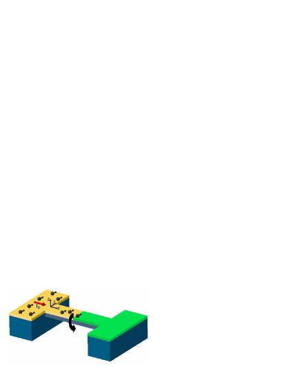
In this Letter we will consider NMS in the form of a suspended beam with a doped semiconductor film epitaxially grown on its surface (see Fig. 1). An analysis of the SOI in this system shows that the flexural and torsion vibrational modes couple most efficiently to the electron spin. As a simple example, we will focus on the torsion mode. The strain associated with torsion produces the spin-orbit field which is linear with respect to the electron momentum and is directed perpendicular to it. This field varies in time and space according to respective variations of the torsion strain. Due to the linear dependence on the momentum, the SOI looks precisely as interaction with the spin dependent electromagnetic vector potential. An immediate result of this analogy is that the time-dependent torsion gives rise to a motive force on electrons. Such a force, however, acts in different directions on particles with oppositely oriented spins, inducing thus the spin current in the electron gas. The physics of this phenomenon is very similar to the spin current generation under time-dependent Rashba SOI, where the time dependence of the SOI coupling parameter is provided by the gate voltage variations Malsh . In the present work we will focus, however, on the inverse effect. Due to the SOI coupling, the spin current flowing through the beam is expected to create a mechanical torsion. The torque effect on NMS due to spin flow has been previously predicted by Mohanty et. al. Mohanty for a different physical realization, where the torque has been created by spin flips at the nonmagnetic-ferromagnetic interface. They also suggested an experimental setup to measure such a small torque. As it will be shown below, the torque due to the strain induced SOI can be large enough to be measured using the experimental setup proposed in Ref. Mohanty . Besides this method, other sensitive techniques for displacement measurements can be employed measurements .
The system under consideration is a rectangular beam of the total length , width , and thickness . The coordinate axes are chosen as shown in Fig. 1. The semiconductor film with the thickness occupies the length of the beam. The rest part contains a metal film. It can also include some additional elements for detection of the torque, for example in Ref. Mohanty . Here we will consider an example when the spin current is created by diffusion of the spin polarization from the left contact in Fig. 1. Therefore, there is no electric current flow through NMS. The spin polarization diffuses towards the metal film which, due to its relatively high conduction, can play an important role as a reservoir for the spin polarization relaxation.
We start from the strain-induced SOI Soibystrain described by the Hamiltonian
| (1) | |||||
where are elements of the strain tensor, stand for Pauli matrices and denote components of the electron wave vector. In the narrow gap semiconductors the parameter is usually much smaller than Soibystrain . Therefore, the term proportional to will be omitted below. Besides the strain-induced , the total SOI Hamiltonian also includes the strain independent interaction . Because of submicron cross-section dimensions of the doped semiconductor film, will be determined by the bulk Dresselhaus term Dresselhaus .
| (2) |
This interaction, in the range of doping concentrations 1017cm-3 and higher, provides the main mechanism for spin relaxation in bulk materials Soibystrain .
Since the S-M rod with total length and , the major contribution to the strain comes from flexural and torsion motions of the rod Landau . Within the isotropic elastic model the flexural motions are represented by the diagonal elements and Landau which do not enter into the first square brackets of Eq. (1). On the other hand, due to the crystal anisotropy effects, the components are not zero for such sort of motion and could contribute to Eq. (1). We will consider, however, the simplest example of torsion motions of the rod within an isotropic elastic model. In this case the strain can be represented as Landau
| (3) |
where stands for the rate of torsion determined by the torsion angle . The function depends only on and and is uniquely determined by the rod cross-section geometry.
The next step is to derive from the one-particle interaction Eq. (1) a Hamiltonian which describes a coupling of the spin current to the strain. The electron system carrying the spin current can be described by a density matrix . In the framework of the perturbation theory the leading correction to the electron energy due to the SOI induced strain can be obtained by averaging with . In the semiclassical approximation such a procedure can be represented as averaging over the classical phase space with the Boltzmann distribution function . This function is a 22 matrix in the spinor space. One can also define the spin distribution function . It is normalized in such a way that the local spin polarization We notice that, due to electron confinement in and directions, the averages of containing and turn to zero. Assuming that electron distribution is uniform within the cross-section of the semiconductor film one thus obtains, from Eqs. (1) and (3), the SOI energy
| (4) | |||||
This expression can be further simplified taking into account that turns to zero on a free surface Landau . Hence, in the example under consideration on the top and side surfaces of the doped semiconductor film. Consequently, the second term in Eq. (4) vanishes after integration over . Now Eq. (4) can be expressed in terms of the spin current which is the flux in -direction of -polarized spins.
| (5) |
where is the semiconductor film cross-section and is the electron velocity in -direction comment . Finally, Eq. (4) can be transformed to
| (6) |
Here the coupling constant is given by
| (7) |
where .
From the last equation, it is seen that the spin-polarized flow imposes a distributed torque on the rod. In order to study this effect in detail we will neglect, for simplicity, the difference between elastic constants of semiconductor and metal parts of NMS. As such, the equation of motion for the torsion angle can be then written as
| (8) |
where denotes the Heaviside function, stands for the torsion rigidity, and is the moment of inertia. It is easy to figure out that the torque imposed by the SOI on NMS can be expressed as
| (9) |
and, for the S-M rod clamped on both ends, the torsion angle at
| (10) |
where is the total length of the rod. From Eq. (8) one can easily see that if the semiconductor film covers the entire length of the beam () and the spin current is homogeneous along it, the last term in Eq. (8) turns to 0. Consequently, for a doubly clamped beam the solution of Eq. (8) is . In this case, in order to obtain the finite torsion angle, the NMS must include films with different spin-orbit coupling parameters , as in Fig. 1 where in the metal film. On the other hand, if depends on , as in the example considered below, the metal film is not so necessary. In this example it is shown, however, that such a film can be useful as a reservoir for fast spin relaxation, enhancing thus the diffusive spin current flow through the beam.
In order to evaluate the torque, let us adopt the following simple model, which is also convenient for an experimental realization. Namely, we assume that the spin current is due to spin diffusion from the left contact. The spin polarization can be created there by various methods ranging from absorption of circularly polarized light to injection from a ferromagnet Rev.Mod.Phys . One more possibility is the electric spin orientation Kato . For the steady state the diffusion equation reads
| (11) |
where and are diffusion coefficients and spin relaxation times, with the subscript indicating the physical quantities in semiconductor (i=S) or metal (i=M) regions. At the semiconductor-metal interface the diffusion current and magnetization must be continuous, where is the semiconductor or metal density of states at the Fermi energy Johnson . We will assume that the length of the metal part of the rod is larger than the spin diffusion length . Therefore, the spin current passes through the semiconductor film and further decays within the metal film. Obviously, in the considered example there is no charge current through the system. Solving the diffusion equation for and , where and are the 3D conductivities of metal and semiconductor, respectively, we obtain
| (12) |
Since the ratio is very big, Eq. (12) is valid in a broad range of not very small .
For a numerical evaluation of the spin-orbit torsion effect we take nm and nm. The SOI coupling constant m/sec in GaAs Dyakonov . From Eq. (7) and Ref. Landau , it is easily to obtain the spin-current–torsion coupling parameter , where is a numerical factor depending on the ratio . At the factor . For such numerical parameters we find J sec. It is interesting to compare the torsion effect from the strain induced SOI with that produced by spin flips at the FM-NM interface Mohanty . In the latter case , where is of the order of the spin current injected at the FM-NM contact when the electric current passes through it. Comparing this expression with Eq. (9), it is seen that at the same spin currents the SOI effect is much stronger, by the factor . On the other hand, in Mohanty the FM-NM contact can be fabricated from all metallic components, while our device must contain the narrow gap semiconductor film. In the former case NMS is able to carry much larger spin current, due to the weaker, by the factor , Joule heating effect. However, the measurement setup suggested by Mohanty et. al Mohanty allows to measure torsion effects produced by quite weak currents. For example, at Amp the torque N m, which is within the sensitivity claimed in Mohanty . Moreover, the measurement sensitivity can be enhanced Mohanty_pc . Within our model we can evaluate the spin polarization which can produce a measurable effect on NMS. From Eq. (12), taking , the typical low temperature diffusion constant 300 cm2/sec and cm-3, one obtains nA. Hence, a measurable nA spin current in NMS can be created by diffusion of spin polarization from an adjacent reservoir containing only of spin-polarized carriers. Various methods Rev.Mod.Phys ; Wunderlich ; Kato are able to provide such and even much larger spin polarization. Higher spin currents are, however, restricted by the heating effects, which depend on the practical design of NMS.
It should be noted that the torsion measurement method of Ref. Mohanty applies to a time-dependent torque in resonance with a NMS oscillation. For such a measurement the spin current could be modulated in time by a narrow gate between the left contact and the rod, or by varying the spin polarization in the left reservoir, for example, if it is created by absorption of circularly polarized light with modulated intensity.
The static torsion angle at can be found from Eq. (10). On the other hand, the maximum torsion effect is obtained for the time-dependent spin current in resonance with the NMS fundamental oscillation. In this case, the torsion angle in Eq. (10) must be multiplied by , where is the resonance quality factor, which can be quite large in NMS. To observe this torsion angle it must be much larger than the mean amplitude of its thermal fluctuations . For a doubly clamped rod
| (13) |
For a rectangular cross-section with , the torsion rigidity Landau , where in GaAs material. Taking and all other parameters the same as in the previous paragraph, and mK we obtain the ratio at nA.
We have considered a simple example of the spin-orbit torque effect produced by spin flux in a diffusive 3D semiconductor film. It would be interesting to study other systems, for example, a superlattice of remotely doped high mobility quantum wells in the ballistic regime ( is less than the elastic mean free path). In such a system energy dissipation within the semiconductor film is reduced and, apparently, larger spin currents are allowable.
In summary, we propose a nanomechanical system where due to the
strain-induced spin-orbit interaction the electron spin degree of
freedom can couple to NMS mechanical motions. We have shown that
this coupling is strong enough to induce the measurable torsion in
NMS when the spin polarization flows through the suspended nanobeam.
Besides a potential for other possible applications, such NMS can be
employed as a sensitive detector of spin currents and spin
polarizations. The basic structure can be further modified to create
devices for eventual use in spintronics as well as spin information
processing.
This work was partly funded by the Taiwan National Science Council; and RFBR grant No. 03-02-17452.
References
- (1) Semiconductor Spintronics and Quantum Computation, edited by D. D. Awschalom, N. Samarth, and D. Loss (Springer-Verlag, Berlin, 2002).
- (2) S. A. Wolf, et. al., Science 294, 1488 (2001).
- (3) I. Ẑutić, J. Fabian, and S. Das Sarma, Rev. Mod. Phys. 76, 323 (2004).
- (4) J. Sinova, et. al., Phys. Rev. Lett. 92, 126603 (2004); S. Murakami, N. Nagaosa and S. Zhang, Science 301, 1348 (2003); V. M. Edelstein, Solid State Commun., 73, 233 (1990); A. Voskoboynikov, S. S. Liu, and C. P. Lee, Phys. Rev. B 59, 12514 (1999); L. S. Levitov and E. I. Rashba Phys. Rev. B 67, 115324 (2003).
- (5) S. Datta and B. Das, Appl. Phys. Lett. 56, 665 (1990); P. Sharma and P. W. Brouwer, Phys. Rev. Lett. 91, 166801 (2003); M. Governale, F. Taddei, and R. Fazio, Phys. Rev. B 68, 155324 (2003).
- (6) A. G. Mal’shukov, C. S. Tang, C. S. Chu, and K. A. Chao, Phys. Rev. B 68, 233307 (2003).
- (7) C. S. Tang, A. G. Mal’shukov, and K. A. Chao, Phys. Rev. B 71, 195314 (2005).
- (8) J. Wunderlich, B. Käestner, J. Sinova, and T. Jungwirth, Phys. Rev. Lett. 94, 047204 (2005).
- (9) Y. K. Kato, et. al., cond-mat/0502627.
- (10) G. E. Pikus and A. N. Titkov, in Optical Orientation, edited by F. Meier and B. P. Zakharchenya (North-Holland, Amsterdam, 1984).
- (11) M. L. Roukes, Phys. World 14, 25 (2001); H. G. Craighead, Science 290, 1532 (2000); A. N. Cleland, Foundations of Nanomechanics (Springer, Berlin, 2003).
- (12) P. Mohanty, G. Zolfagharkhani, S. Kettemann, and P. Fulde, Phys. Rev. B 70, 195301 (2004).
- (13) R. G. Knobel, A. N. Cleland, Nature 424 291 (2003).
- (14) L. Landau and E. Lifshitz, Course of Theoretical Physics (Pergamon Press, New York, 1986), 3rd ed., Vol. 7.
- (15) G. Dresselhaus, Phys. Rev. 100, 580 (1955).
- (16) We neglected the small correction to the spin current associated with Dresselhaus’s term in the velocity operator, as well as the corresponding correction due to , within the linear perturbation theory on the strain induced SOI.
- (17) M. Johnson and R. H. Silsbee, Phys. Rev. B 35, 4959 (1987); 37, 5312 (1988).
- (18) M. I. D’yakonov, V. A. Marushchak, V. I. Perel’, and A. N. Titkov, Sov. Phys. JETP 63, 655 (1986), [Zh. Eksp. Teor. Fiz. 90, 1123 (1986)].
- (19) P. Mohanty, private communication.