Magnetic Metamaterials at Telecommunication and Visible Frequencies
Abstract
Arrays of gold split rings with a 50-nm minimum feature size and with an resonance at 200 THz frequency (1.5 wavelength) are fabricated. For normal-incidence conditions, they exhibit a pronounced fundamental magnetic mode, arising from a coupling via the electric component of the incident light. For oblique incidence, a coupling via the magnetic component is demonstrated as well. Moreover, we identify a novel higher-order magnetic resonance at around 370 THz (800 nm wavelength) that evolves out of the Mie resonance for oblique incidence. Comparison with theory delivers good agreement and also shows that the structures allow for a negative magnetic permeability.
©2005 The American Physical Society
pacs:
42.70.a, 42.25.p, 78.20.CiIn usual crystals, the atoms are arranged in a periodic fashion with lattice constants less than 1 nm. This is orders of magnitude smaller than the wavelength of visible light. Thus, the light experiences an effective homogeneous material; it does not “see” the underlying periodicity (apart from crystal symmetries). Microscopically, the light excites electric dipoles that reradiate with a certain retardation, slowing down the phase velocity of light in the material by a factor called the index of refraction. Metamaterials are artificial periodic structures with “lattice constants” that are still smaller than the wavelength of light. Again, the light field “sees” an effective homogeneous material. The “atoms,” however, are not real atoms but are rather artificial nanostructures composed of many atoms. This allows for tailoring their properties in a way not possible with normal atoms. Indeed, Pendry Pendry1999 showed that a combination of “magnetic atoms” and “electric atoms” (i.e., split-rings and metallic wires) with negative permeability and permittivity , respectively, can lead to materials with a negative index of refraction Veselago1968 . These materials open a whole new chapter of photonics connected with novel concepts and potential applications Pendry2000 ; Smith2004 .
The main technological challenge is to obtain a negative permeability at telecom or visible frequencies, which does not occur in natural materials. Starting with first demonstrations in the microwave regime Shelby2001 , the achieved magnetic resonance frequencies have increased by more than 4 orders of magnitude over the last four years Shelby2001 ; Yen2004 ; Linden2004 ; Zhang2005 ; Moser2005 ; Katsarakis2005 , reaching a record of 100 THz (3 wavelength) in November 2004 Linden2004 .
So far, the “magnetic atom” of choice has been the split ring resonator (SRR), in essence just a small LC circuit consisting of an inductance L and a capacitance C. The resonance frequency of this LC circuit scales inversely with its size, provided the frequencies are significantly below the metal plasma frequency. Near the resonance, the current in the inductance can lead to a magnetic field opposing the external magnetic field of the light, hence enabling .
The design used here closely follows our recent approach based on arrays of single SRR Linden2004 ; Katsarakis2004 . The structures are fabricated using standard electron-beam lithography on a 1 mm thick glass substrate coated with a 5 nm thin film of indium-tin-oxide (ITO), in order to avoid charging effects of the poly(methyl methacrylate) resist layer (PMMA 950k) during the exposure. The gold film thickness is 30 nm. To increase the resonance frequency at a given minimum feature size and to simplify the nanofabrication, we almost eliminate the tiny upper arms of the SRR, leading to more “U”-shaped structures (see Fig. 1 (a)). Intuitively, these Us correspond to of one winding of a magnetic coil with inductance L. The ends of the U-shaped wire form the capacitance C. We employ periodic quadratic arrays of such SRR with the dimensions apparent from the electron micrographs in Fig. 1.
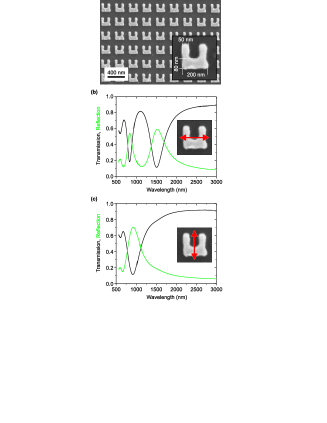
Figure 1 connects to our previous work Linden2004 and shows spectra taken under normal incidence with a commercial Fourier-transform microscope spectrometer online_material . If the incident light is polarized horizontally, the electric field can couple to the capacitance of the SRR and induce a circulating current in the coil leading to a magnetic-dipole moment normal to the SRR plane. Note that this resonance at 1.5 wavelength is yet more pronounced than in our previous work Linden2004 at 3 , due mainly to the increased ratio between thickness and lateral size of the SRR. The magnetic resonance disappears for vertical incident polarization (Fig. 1(c)), leaving behind only the Mie resonance of the SRR around 950 nm wavelength. As this resonance will become important below as well, we briefly recapitulate its physics. Here the electric field of the light leads to a charge accumulation at the surfaces of the vertical SRR arms, resulting in a depolarization field. Depending on the permittivity of the metal, hence depending on the frequency of light, this depolarization field can enhance or suppress the external electric field. (We also observe a weaker short-wavelength Mie resonance around 600-nm in Fig. 1, which is due to the depolarization field of the short axis, i.e., the width of the SRR arms.) Notably, the fundamental Mie resonance of our SRR changes in spectral position and width between the two different polarization configurations. This can be understood as follows: For horizontal incident polarization and for the frequencies of interest here, only the fundamental Mie resonance of the SRR bottom arm is excited. For vertical polarization, the two similarly shaped vertical SRR arms contribute. The latter are coupled via the SRR’s bottom arm (and via the radiation field). As usual, the coupling of two degenerate modes leads to an avoided crossing with two new effective oscillation modes, a symmetric and an antisymmetric one, which are frequency down-shifted and up-shifted as compared to the uncoupled resonances, respectively. The antisymmetric mode cannot be excited at all for normal incidence as it has zero effective electric-dipole moment. The redshifted symmetric mode can be excited. It even has a larger effective electric-dipole moment than a single arm.
The optical response of SRR is not only polarization-dependent but also highly anisotropic. Thus, we have performed transmission experiments under oblique incidence (Fig. 2) using a dedicated home-built setup online_material . Compared with the Fourier-transform microscope spectrometer used above, this setup has improved polarization optics by using Glan-Thomson polarizers and a smaller effective opening angle ( degrees). It still allows one to investigate a sample of size (100 m)2 with a large angle of incidence with respect to the surface normal over a broad spectral range. In Fig. 2(a), the electric component of the incident light can not couple to the LC circuit resonance for any angle. With increasing angle, however, the magnetic field acquires a component normal to the SRR plane. This component can induce a circulating electric current in the SRR coil via the induction law (see right-hand side inset in Fig. 3(a)). This current again leads to a magnetic-dipole moment normal to the SRR plane, which can counteract the external magnetic field. The magnitude of this resonance (highlighted by the blue area around 1.5 wavelength) is indeed consistent with theory (see below) and leads to an effective negative magnetic permeability for propagation in the SRR plane and for a stack of SRR layers rather than just one layer considered here. This aspect has been verified explicitly by retrieving the effective permittivity and permeability from the calculated transmission and reflection spectra retrieval_Smith ; retrieval_Koschny . The shape of the retrieved magnetic permeability closely resembles that published in our previous work Linden2004 at 3 wavelength. It exhibits a negative permeability with a minimum value of at 1.67 wavelength online_material . This value could be further improved by increasing the number of SRR per area (compare Fig. 1(a)), hence increasing the “oscillator strength” of the magnetic resonance.
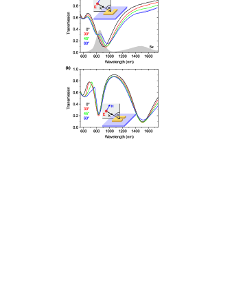
Another striking feature of the spectra in Fig. 2(a) is that the 950 nm wavelength Mie resonance at normal incidence splits into two resonances for oblique incidence. This aspect can be understood continuing along the lines of our above intuitive discussion: For finite angles of incidence, the phase fronts of the electric field are tilted with respect to the SRR plane. Thus, the vertical SRR arms are excited with a small but finite time delay, equivalent to a finite phase shift. This shift allows coupling to the antisymmetric mode of the coupled system of the two vertical arms as well. In one half cycle of light, one gets a positive charge at the lower left-hand side corner of the SRR and a negative charge at the lower right-hand side corner, resulting in a compensating current in the horizontal bottom arm. Characteristic snapshots of the current distributions in the SRR are schematically shown as insets in Fig. 3(a). Altogether, we get a part of a circulating current, leading to a magnetic-dipole moment. This type of magnetic resonance has not been observed before. Its spectral position of 800 nm at 60∘ angle in Fig. 2(a) is just within the visible regime – for the first time, one can literally see a magnetic resonance.
According to our reasoning for oblique incidence (e.g., 60∘), we expect a circulating current component for wavelengths near the two magnetic resonances at and 800 nm, respectively. Any circulating current is evidently connected with a current in the horizontal bottom arm of the SRR. According to the usual laws of a Hertz dipole, the corresponding charge oscillation in the bottom arm can radiate into the forward direction with an electric field component orthogonal to the incident polarization. In other words, for oblique incidence, the fingerprint of the magnetic resonances is a rotation of polarization. Such rotation is indeed unambiguously observed in our experiments (see gray area in Fig. 2(a)), strongly supporting our above interpretation.
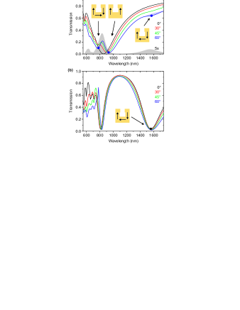
Figure 2(b) shows spectra for a second polarization configuration in which both the electric and the magnetic component of the light field can couple to the SRR for oblique incidence. The same configuration was used in Ref. Yen2004 . Our results immediately show that coupling to the fundamental magnetic resonance at 1.5 wavelength is not mediated by the magnetic field alone here. The two further independent polarization and angle configurations are consistent with our above interpretation but do not reveal any additional resonances online_material .
In order to further strengthen our above interpretation of the different resonances, we compare the measured spectra with theory. It turns out that numerical calculation of spectra for oblique incidence is much more of a challenge than for normal incidence or for propagation in the plane of the SRR array. Thus, we have not only followed our previous finite-difference time-domain approach Linden2004 but also an advanced frequency-domain based finite-element approach. We discretize the geometry of a unit cell () including the SRR and the surrounding layered media with an unstructured mesh of tetrahedra. The coarse mesh is automatically refined to a fine mesh consisting about 6000 tetrahedra. Bloch-periodic boundary conditions are applied in the and directions Burger2004 with lattice constants of and , respectively. In the direction we apply transparent boundary conditions Zschiedrich2005 . To avoid dealing with the complex SRR shape apparent from Fig. 1, the three SRR arms are approximated as rectangles with a width of 65 nm for the two vertical arms and 90 nm for the bottom arm. These values have been fine-tuned to fit the calculated to the measured resonance positions. The SRR side length of 200 nm and the gold thickness of 30 nm are identical to the values already quoted above. For the permittivity of gold we assume a wavelength dependence according to the Drude model, with a plasma frequency of and a collision frequency of . The permittivity of the ITO layer (glass substrate) is taken as 3.8 (2.25). We discretize Maxwell’s equations using vectorial finite elements (Whitney elements) of second polynomial order. The resulting sparse matrix equation (with about 130 000 unknowns corresponding to the solution on the fine mesh) is solved on a standard personal computer by either standard linear algebra decomposition techniques or multigrid algorithms, depending on the problem size.
Figure 3 exhibits calculated spectra for different angles of incidence. The graphical representation is identical to that of the experiment (see Fig. 2). Obviously, the qualitative agreement between experiment and theory is excellent. Especially the spectral positions as well as the magnitudes of the different resonances and the rotation of the polarization (gray area at the bottom of Fig. 3(a)) are well reproduced. For normal incidence, the spectra calculated with the finite-element frequency-domain approach agree well with those obtained from the finite-difference time-domain simulations, which are used for the retrieval procedure (see above). The schematic insets shown in Fig. 3 have been derived from the movies online_material of the calculated field distributions and correspond to the qualitative discussion given above.
In conclusion, normal optical materials exhibit only an electric-dipole response. Here we have demonstrated pronounced magnetic-dipole modes at 1.5 and at 800 nm wavelength, respectively. The one at 1.5 is the “usual” resonance of the split ring resonators and would lead to a negative magnetic permeability indeed. The one at 800 nm wavelength is a higher-order magnetic resonance, which is identified here for the first time. On the one hand, the nanofabrication of magnetic metamaterials at these frequencies requires much more of a technological effort than at microwave frequencies. On the other hand, linear optical spectroscopy can be performed much more conveniently and in a more controlled fashion. Moreover, the availability of lasers in this spectral regime enables future nonlinear optical experiments.
We acknowledge the support by the DFG-Center for Functional Nanostructures within subproject A 1.5, by DFG project We-1497/9-1, by DFG priority programme SPP 1113, and by the BMBF within project 13N8252. The research of C. M. S. is further supported by the Alexander von Humboldt senior-scientist award 2002, by Ames Laboratory (Contract No. W-7405-Eng-82), EU FET project DALHM and DARPA (Contract No. MDA 972-01-2-0016).
Note added in proof. – Similar U-shaped SRR have recently also been discussed theoretically in wirepair3 .
References
- (1) J. B. Pendry, A. J. Holden, D. J. Robbins, and W. J. Stewart, IEEE Trans. Microwave Theory Tech. 47, 2075 (1999).
- (2) V. G. Veselago, Sov. Phys. Usp. 10, 509 (1968).
- (3) J. B. Pendry, Phys. Rev. Lett. 85, 3966 (2000).
- (4) D. R. Smith, J. B. Pendry, and M. C. K. Wiltshire, Science 305, 788 (2004).
- (5) R. A. Shelby, D. R. Smith, and S. Schultz, Science 292, 77 (2001).
- (6) T. J. Yen, W. J. Padilla, N. Fang, D. C. Vier, D. R. Smith, J. B. Pendry, D. N. Basov, and X. Zhang, Science 303, 1494 (2004).
- (7) S. Linden, C. Enkrich, M. Wegener, J. Zhou, T. Koschny, and C. M. Soukoulis, Science 306, 1351 (2004).
- (8) S. Zhang, W. Fan, B. K. Minhas, A. Frauenglass, K. J. Malloy, and S. R. J. Brueck, Phys. Rev. Lett. 94, 37402 (2005).
- (9) H. O. Moser, B. D. F. Casse, O. Wilhelmi, and B. T. Saw, Phys. Rev. Lett. 94, 63901 (2005).
- (10) N. Katsarakis, G. Konstantinidis, A. Kostopoulos, R. S. Penciu, T. F. Gundogdu, M. Kafesaki, E. N. Economou, Th. Koschny, and C. M. Soukoulis, Opt. Lett. 30, 1348 (2005).
- (11) N. Katsarakis, Th. Koschny, M. Kafesaki, E. N. Economou, and C. M. Soukoulis, Appl. Phys. Lett. 84, 2943 (2004).
- (12) See EPAPS document No. E-PRLTAO-95-075545 for additional information on the optical characterization of the SRR arrays and on the retrieval procedure (http://www.aip.org/pubservs/epaps.html).
- (13) D. R. Smith, S. Schultz, P. Markos, and C. M. Soukoulis, Phys. Rev. B 65, 195104 (2002).
- (14) Th. Koschny, P. Markos, E. N. Economou, D. R. Smith, D. C. Vier, and C. M. Soukoulis, Phys. Rev. B 71, 245105 (2005).
- (15) S. Burger, R. Klose, A. Schädle, F. Schmidt, and L. Zschiedrich, Proc. SPIE Vol. 5728, 164 (2005).
- (16) L. Zschiedrich, R. Klose, A. Schädle, and F. Schmidt, J. Comput. Appl. Math., (in press).
- (17) V. A. Podolskiy, A. K. Sarychev, E. E. Narimanov, and V. M. Shalaev, J. Opt. A Pure Appl. Opt. bf 7, S32 2005.