Continuous ‘fish scale’ planar electromagnetic meta-material
Abstract
We report on a new type of continuous electromagnetic metal planar meta-material, which resembles a ‘fish scale’ structure. It is highly transparent to electromagnetic radiation throughout a broad spectral range apart from at one isolated wavelength. When the structure is superimposed on a metallic mirror it becomes a good broadband reflector everywhere apart from one wavelength where the reflectivity is small. At this wavelength the reflected wave shows no phase change with respect to the incident wave, thus resembling a reflection from a hypothetical zero refractive index material, or ‘magnetic wall’. We also discovered that the structure acts as a local field concentrator and a resonant ‘amplifier’ of losses in the underlying dielectric.
In optics, spectral selectivity in components such as filters, beam-splitters and mirrors has traditionally been realized by accurately engineering constructive and destructive multiple interference of light in a stack of dielectric layers with of thicknesses comparable to the wavelength. Spectral selectivity of light transmission and reflection may also be found in regular three-dimensional structures commonly know as photonic band-gap crystals. However, another opportunity exists to achieve spectral selectivity of transmission and reflection in a thin, essentially sub-wavelength layer of material without engaging multiple beam diffraction and interference. Wavelength sensitive transmission and reflection of a thin layer may result from patterning the interface on a sub-wavelength scale in a way that makes electromagnetic excitation couple to the structure in a resonant fashion. The idea of frequency selective planar structures has been investigated in the microwave part of the spectrum for some time using arrays of separated holes in a metal screen or particles such as crosses, snowflakes, tapers and split-ring resonators Vardaxoglou (1997). Similar research on the extraordinary transmission of isotropic Barnes et al. (2003) and anisotropic Elliott et al. (2004) arrays of holes in the optical part of the spectrum has recently attracted a lot of attention. In this paper we point out, however, that to achieve narrow spectral resonances continuous periodic structures may be used.
Here we report the first experiential results on a new type of continuous planar meta-material structure - an equidistant array of meandering metallic strips on a thin dielectric substrate producing a pattern that resembles fish scales. In the past similar structures have only been investigated theoretically Prosvirnin et al. (2002), Mladyonov et al. (2003). We show experimentally that the fish scale structure exhibits several interesting properties when interacting with electromagnetic radiation. First, it is highly transparent to electromagnetic radiation across a wide spectral range apart from at one isolated wavelength. Second, when such a structure is combined with (superimposed on) a homogeneous metallic mirror with a sub-wavelength dielectric spacing it becomes a good broadband reflector apart from at an isolated wavelength where reflectivity is small. Third, at this wavelength, there is no phase change of the reflected wave with respect to the incident wave. This last property is particularly unusual because on reflection from a conventional unstructured metal or dielectric surface with refractive index , the electric field of the wave accrues a phase reversal (phase shift of 180 deg.). Indeed , so reflection without a phase change () implies an interface with a bulk homogeneous medium of zero refractive index, . In microwave literature this phenomenon is often referred to as reflection from a ‘magnetic wall’ Sievenpiper et al. (1999)). Finally, the structure acts as a local field concentrator and a resonant multi-fold ‘amplifier’ of losses in the constitutive dielectric.
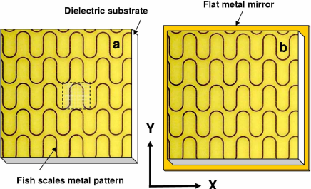
In the experiments reported here we used a fish scale structure with a square translation cell of that was etched from a copper film on a fiberglass PCB material of thickness (see Fig. 1). The width of the strips was . The overall size of the samples was approximately . We studied the reflection and transmission of this structure in the spectral range. The measurements were performed in an anechoic chamber using a vector network analyzer (Agilent, model E8364B) and horn antennas (Schwarzbeck M. E. model BBHA 9120 D). The structure does not diffract electromagnetic radiation for frequencies lower than and therefore a single-wave regime was achieved in the transmission and reflection experiments.
The results of a transmission experiment under normal incidence conditions are presented in Fig. 2. The most dramatic spectral selectivity is seen for the polarization state of incident light parallel to the meandering metal strips (the -polarization as defined in Fig. 1). Here the transmission losses of the meander structure are very small everywhere apart from in a sharp trough in transmission at . The resonant width at from the bottom of the trough is . For the orthogonal -polarization (perpendicular to the meandering strips) the transmission peak is shifted to and the resonance width is about .
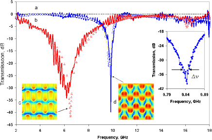
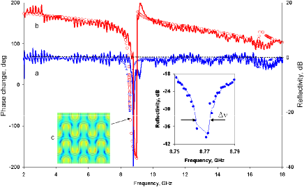
Fig. 3 shows the results of a reflection experiment in which the structure is combined with a homogeneous metallic copper sheet mirror placed in contact with the opposite side of the dielectric substrate supporting the fish scale structure, i.e. at a distance of from the fish scale structure. We studied reflection under nearly normal incidence conditions with the incident wave entering the sample at to the normal and with the plane of incidence perpendicular to the line of the meandering strips.
Without a fish scale structure on top one would expect a metallic sheet to be a very good reflector across the entire spectral range of interest, and that the reflected wave would have the opposite phase to the incident wave. What we found is that with an -polarized incident field the reflection losses are small everywhere apart from in a trough at . The resonant width at from the bottom of the trough is . Refection for the perpendicular -polarization is nearly perfect everywhere apart from in a much smaller trough at . For the -polarization we observed that the reflected wave’s phase change has a strong dispersion and that the phase difference between the incident and reflected wave passes zero in the proximity of the the resonance, at .
The origin of the array’s resonant features for -polarized incident radiation and their dependence on the characteristic dimensions of the pattern becomes apparent if one considers the structure as a sequence of straight-line strips periodically loaded with short-circuit sections of length where is the full length of the strip within the elementary translational cell Prosvirnin et al. (2002). The wavelength of excitation in the structure , so the line impedance has zero value at , corresponding to a maximum in reflection and minimum in transmission. The substrate material used to manufacture the fish scale structure had and an estimated reflection resonance frequency of , in very good agreement with the measured value of for the minimum transmission frequency (see Fig. 2). It is difficult to produce a simple and accurate estimate for the resonant frequency for -polarized incident radiation, however this resonance seems to appear when the wavelength of excitation in the strip is approximately equal to . Corresponding field distributions for - and -polarized excitations in the plane of the structure are illustrated in the insets to Fig. 2. They have been calculated using the true three-dimensional finite-element method for solving Maxwell’s equations in the spectral presentation. The more localized current distribution seen at resonance for the -polarization indicates weaker coupling between the array and the free-space wave, and this manifests itself as a much narrower resonance in comparison with the -polarization.
For the fish scale structure on a metal-backed substrate the following formula can be used to estimate the wavelength of the excitation in the strips: , where is the width of the strip and is the substrate thickness. Now, for the -polarization the resonance occurs at a frequency where is close to half of the length of the strip inside the elementary translation cell, i.e. . This estimation gives a resonant frequency of which coincides with the experimentally measured value. A resonance for the -polarization occurs when . The corresponding predicted resonant frequency is , which is in a good agreement with the measured value of .
We also modelled the far-field response of the fish-scale structure using the method of moments Prosvirnin et al. (2002). This numerical method involves solving the integral equation for the surface current in the metal pattern by the field of the incident wave. This is followed by calculations of scattered fields as a superposition of partial spatial waves. The metal pattern is treated as a perfect conductor, while the substrate is assumed to be a lossy dielectric. For transmission through the fish scale structure the theoretical calculations show very good agreement with the experimental results (see Fig. 2). The numerical calculation also accurately describes all of characteristic trends seen in the reflection experiment from the combined fish scale/metal mirror structure, and predicts the dramatic switching of the reflected signal phase at the resonance for the -polarization (see Fig. 3). Both the experimental results and calculations show the phase of the reflected wave changing sign and passing zero at about , which is somewhat unusual behavior. At zero phase change the reflected wave has the same sign as the incident wave. In contrast, a wave reflected from a conventional unstructured metal or dielectric surface has the opposite sign to the incident wave. If the interface was loss-less, which it could be in the case of an ideal metal and a non-absorbing dielectric support, the zero phase change would correspond to reflection from an interface with a bulk homogeneous medium of zero refractive index, .
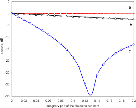
Reflection from a flat mirror superimposed with the fish scale structure shows another intriguing and potentially useful property - ‘loss amplification’. Assuming that the strip structure and the mirror are made out of ideal metal and that the dielectric is loss-less, one would expect the reflected wave to have the same amplitude as the incident wave. Thus, the trough in the reflected signal, experimentally observed at the zero-phase frequency point, should not appear for loss-less media. The only reason for such a trough could be dissipative losses (other sources of losses such as diffraction are not present in this structure because the patterning period is smaller than the wavelength). However, in the microwave part of the spectrum losses in copper are negligible, indeed reflection losses for a free-standing copper mirror at are about . For a copper mirror with a dielectric substrate in front of it the losses related to the double pass of the wave through the substrate would only be a fraction of a decibel for the microwave material used in our experiment. A simple loss mechanism cannot by any means explain the high losses ( ) observed in the experiment at and their sharp resonant character. To explain strong resonant losses we calculated, using the method of moments, the intensity of the reflected signal as a function of losses in the substrate at the resonance (see Fig. 4). With increasing losses in the dielectric substrate (i.e. increasing value of the imaginary part of the substrate’s permittivity) reflection losses for a simple metallic mirror on the substrate are small for a low-loss dielectric () (curve (a), Fig. 4). The attenuation of the reflected signal due to dielectric losses can reach a few dB at resonance for the fish scale structure without a mirror behind it (curve (b) Fig. 4). In contrast, the calculations predict strong resonant losses on reflection from the fish scale structure when it is backed by a metallic mirror on the low-loss substrate (curve (c), Fig. 4). These calculations perfectly correlate with our experimental observations (Fig. 3a) and show that at the zero-phase point the fish scale structure dramatically ‘amplifies’ the small losses of the dielectric. This resonant amplification is related to the local field factor i.e. the high concentration of field between the strips of the fish scale design and the mirror plane.
The unusual loss amplification property of the fish scale structure may be used for spectroscopy and characterization of materials where the application of a fish scale structure to a sheet or film of material could dramatically ‘amplify’ its otherwise undetectable losses. The weak sensitivity of a photo-detector outside its main frequency band may be resonantly enhanced if a fish scale structure is used as a light-harvesting material to enhance small tail inter-band absorbtion. Here a photosensitive material should replace the substrate dielectric of the structure. This approach may be particularly efficient in semiconductor detectors and for increasing the quantum efficiency of photomultipliers. A frequency-selective detector may also be created with help of this structure. The x-y anisotropy of the fish scale structure may be used in wave-plates (retarders) for controlling the polarization state of transmitted and reflected electromagnetic radiation. The ongoing development of nano-fabrication techniques may well lead eventually to the use of the fish scale structures in the optical part of spectrum.
Acknowledgements.
The authors would like to acknowledge the assistance of M. V. Bashevoy, S. Birtwell and K. F. MacDonald in CAD design and preparation of the manuscript and the financial support of the Engineering and Physical Sciences Research Council, UK.References
- Vardaxoglou (1997) J. C. Vardaxoglou, Frequency selective surfaces (Research Studies Press LTD., England, 1997).
- Barnes et al. (2003) W. L. Barnes, A. Dereux, and T. W. Ebbesen, Nature 424, 824 (2003).
- Elliott et al. (2004) J. Elliott, I. Smolyaninov, N. I. Zheludev, and A. V. Zayats, Optics letters 29, 1414 (2004).
- Prosvirnin et al. (2002) S. Prosvirnin, S. Tretyakov, and P. Mladyonov, J. Electromagn. Waves Applic. 16, 421 (2002).
- Mladyonov et al. (2003) P. Mladyonov, S. Prosvirnin, S. Tretyakov, and S. Zouhdi, in Proc. 2003 AP-S/URSI conf. (Ohio, USA, 2003), vol. 2, pp. 1103–1106.
- Sievenpiper et al. (1999) D. Sievenpiper, L. Zhang, R. Broas, N. Alexopolous, and E. Yablonovitch, IEEE Trans. Microwave Theory Tech. 47, 2059 (1999).