Two dimensional scaling of resistance in flux flow region in thin films
Abstract
The resistance of thin films has been measured when the angle between the applied fields and -plane of the film is changed continuously at various temperatures. Under various magnetic fields, the resistance can be well scaled in terms of the -axis component of the applied fields at the same temperature in the whole angle range. Meanwhile, we show that the measurement of resistance in this way is a complementary method to determine the growth orientation of the anisotropic high- superconductors.
pacs:
74.25.Qt, 74.25.Fy, 74.25.HaI Introduction
The research on vortex dynamics in high- superconductors ( HTS ) is important since it has close connection with the potential applications in the future. It is known that the vortex system of the strong anisotropic cuprate superconductors, such as or , is very complicated because of high transition temperature and very short coherent length, and the vortex dynamics is particularly rich when a tilted field is applied. Many puzzling experimental phenomena have been observed in the case of tilted vortices for high anisotropic superconductors, for example, one-dimensional chain state of vortex matter observed by Hall probe microscopynature and Bitter decorationBitterDecoration , stepwise behavior of vortex-lattice melting transition in tilted magnetic fieldsStepwise , suppression of irreversible magnetization by in-plane fieldSupression ; Supression2 , etc. The vortex dynamics has been studied extensivelyWen-prl1 ; Wen-prl2 when the magnetic field is applied along -axis of , however, the combined vortex lattice phases still remain largely unexplored in the tilted vortices scenario.
In this paper, we present the resistance of two thin film samples in flux flow region under tilted magnetic fields when the angle between the applied fields and the -plane of the thin film is changed continuously. One of the measured thin film is grown on ( ) substrate, and another is grown on a tilted substrate with the surface plane about 20∘ away from the plane. The resistance as a function of angle demonstrates self-consistency. Moreover, the resistance at the same fixed temperature can be well scaled versus the -axis component of the applied magnetic fields. In addition, the measurement of resistance in this way may offer a complementary method to determine the growth orientation of the highly anisotropic superconductors, and it is a very convenient method to identify the tilt angle of the tilted-growth thin films.
II Experiment Details
The films were deposited onto substrates using the dc magnetron sputtering method. One of which was -axis-oriented film ( denoted as - ), and another ( denoted as - ) was deposited on the substrate with surface cut at an angle about 20∘ with respect to the basal plane( see Fig. 1 (C) ). The details about the preparation of samples can be found in other literaturesyan-apl ; Tilted-20D . The thickness of the thin film is about 3000 Å. The size of - is about 50.5 , and - is patterned into a micro-bridge of 3 in length and 3 in width using photolithography and ion beam etching techniques. The resistance measurement was done with standard four-probe technique. In the case of sample -, the gold leads were attached by silver paste to the gold pads deposited onto the surface of the film. The contact resistance between the electrodes and sample was below 1 . The resistive transition curves are shown in Fig. 2 and the onset transition temperature is about 120 for both samples.
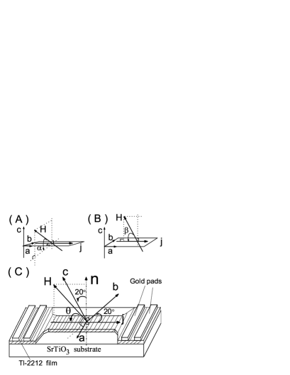

The measurement of resistance was carried out on an Oxford cryogenic MagLab system ( MagLab12Exa ) with magnetic field up to 12 Tesla and temperature ranging from 1.5 to 400 . The resistance was measured by bipolar mode, so each data point was the average of the measured results for the positive and negative transport current. Because the sample platform can be rotated from 0∘ to 360∘ by a controlled step motor during the measurement, the angle between the sample and the magnetic field can be changed from 0∘ to 360 ∘ continuously. So the -plane ( or -axis ) of the film can be coordinated exactly by the minimum ( or maximum ) of the resistance during the rotation of the film under applied field at fixed temperatures in the mixed state. The magnitude of the field and its direction can be varied precisely ( error bar 0.1∘ ) and freely, which is particularly helpful and indispensable for the measurement of the tilted film. In the measurement process, the dc current I, goes through the film along the surface of the film, and the angle between the applied field and the film surface ( or , ) is changed continuously ( see Fig. 1 ). Here, is defined by the angle between the field and the -plane when is always perpendicular to the ( Fig.1 (A) ), is the angle between and -plane when is always in the plane of -axis and ( Fig. 1 (B) ). For the 20∘ tilted film -, or , here is the angle between and the surface of substrate ( Fig. 1 (C) ).
III Results and Discussions
For the film -, we have carefully measured the resistance under various fields at different fixed temperatures in mixed state when ( or ) is changed from 0∘ to 195∘ continuously. For clarity, we only show some typical results here. The resistance under the same applied field at different temperatures are shown in Fig. 3 when the angle and is continuously varied. At the same temperature, as a function of angle and for various fields are displayed in Fig. 4(a) and Fig. 5(a), respectively. It is clearly found that all these resistive curves show symmetry about ( or ) 90∘, which indicates that - is a -axis-oriented thin film. The resistance as a function of the angle demonstrates self-consistency in the whole flux flow region. With angle varying from 0∘ to 180∘, the resistance is changed from the minimum to the maximum and then to the minimum in one cycle, which corresponds to c-axis component of magnetic field changing from the lowest to highest and then to the lowest.
Moreover, it is found that all curves at the same temperature can merge to a common one when we draw as a function of and . For example, the scaling results of all curves at T = 90 K ( Fig. 4(a) and Fig. 5(a) ) are shown in Fig. 4(b) and Fig. 5(b), respectively. In other words, is only dependent on the -axis component of fields, and this law is also obeyed at other temperatures of mixed state.
According to effective mass model, the resistivity of an anisotropic superconductor in the mixed state is dominated by the effective field which can be expressed in the formulaZHWang
| (1) |
here, is the anisotropy parameter ( ). Our results of can be scaled with ( or ) perfectly, the anisotropy parameter of -2212 must be very large. This is consistent with the reported large values of and the nearly two-dimensional limit for Tl-based systemIYE-comments .
In order to understand this 2 scaling law from vortex dynamics, we assume the following simplified phenomenological model based on the fact that the anisotropy parameter of -2212 is very large. Given a , we can simply decompose it into two parts for the case of angle : -axis component and -plane component . As we know, -axis component of field ( ) generates small size pancake vortices ( PVS ) resident in the -panes, which causes dissipation due to the easy motion of PVS driven by in-plane Lorentz force. On the other hand, Josephson vortices ( JVS ) with density proportional to , are formed with the in-plane component of and subjected to the -axis Lorentz driving force, however it is much difficult for the JVS to move across the -planes due to the strong intrinsic pinning of high anisotropic HTS. As a result, the contribution of JVS to is negligible compared to that of PVS. For the case of angle , the only -axis-component field dependence of is mainly due to the absence of Lorentz force for Josephson vortex lines, because is parallel to the in-plane component of field . In fact, can not be ideally in the plane of -axis and , and there exits little Lorentz-force along -axis for JVS. But the strength of the force is negligible compared to the intrinsic pinning.


The issue of anisotropy is related to the dimensionality which is closely connected with the mechanism of HTS, and some unusual transport and magnetic properties have been observed and discussed earlierIYE-comments ; woo-prl ; schmitt-prl ; kes-prl in the strongly anisotropic systems. In these highly anisotropic HTS systems, the Josephson coupling is weak, so the PVS in the adjacent -planes are weakly coupled and the transport and magnetic properties are nearly two dimensionalclem-sst . Therefore, the 2 scaling of our resistive data suggests the thermally-activated dissipation mainly stems from the motion of the PVS in the whole angular range in mixed state for both case of and , which indicates that the two dimensional behavior and the intrinsic anisotropy of the -2212 films are very strong.
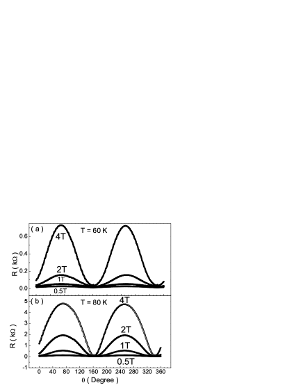
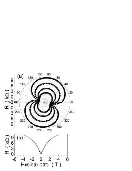
For the thin film of -, we have also measured the resistance as a function of under various fields at different fixed temperatures with changed from 0∘ to 360∘ continuously. The field dependence of resistance as a function of angle is shown in Fig. 6 with (a) T = 60 K , (b) T = 80 K and in Fig. 7(a) with T = 95 K. In each panel, the applied field H is 4 T , 2 T, 1 T, 0.5 T from the top curve to the bottom one. Under the same field H = 4 T, the resistance as a function of angle at various temperatures ( 95 K, 90 K, 80 K ,60 K, 40 K ) is shown in Fig. 7(b). The resistivity of - is three or four magnitude of order larger than that of -, which indicates that the resistance of sample - is mainly controlled by the resistivity along the c-axis. And the -axis resistive dissipation of has been reported previouslyslyuan . Clearly, the symmetric axis of all curves is at ( or 160∘ ), which proves that the -plane of - is truly tilted with respect to the surface of the substrate. This periodic changing of resistance can be displayed obviously by drawing in the polar coordinates, as shown in Fig. 8(a) with T = 95 K. In this sense, the resistance measurement in this way offers a complementary method to determine the growth orientation of high anisotropic HTS, especially for the thin films.
Furthermore, it is found that the resistance at the same temperature can be also scaled in terms of -axis-component field ( ), which is obviously seen from the scaled results at T = 95 K, as shown in the Fig. 8(b). The scaling is poor at the angle , but the scaling has a high quality in wide angle region.
The possible explanation of this scaling is the anisotropy of the upper critical field. In present configuration, assuming that the resistivity can be written as
| (2) |
where is the effective upper critical field. In the anisotropic Ginzburg-Landau model, for an arbitrary field angle is expressed byIYE-comments
| (3) |
Here, denotes the field angle defined from -plane. For the two dimensional systems, this function reduces to , and . As a result, . In this case, the in-plane component field is not enough to destroy the coupling of CuO layers, and the resistance is only dependent on the -axis component of the applied field.
IV Conclusions
In conclusion, we have measured the resistance as a function of angle between the applied field and -plane of the sample when the angle is changed continuously at various temperatures for a -axis-oriented and a tilted -2212 thin films. The resistance with the changed angle demonstrates the special symmetry structure of the sample. Moreover, it is found that the resistance at the same fixed temperature can be well scaled in terms of the -axis component of the applied magnetic fields. Meanwhile, the measurement of resistance in this way can be regarded as a complementary method to determine the growth orientation of the high anisotropic HTS, which is specially helpful for the tilted-growth thin film samples.
Acknowledgments
This work is supported by the National Science Foundation of China, the Ministry of Science and Technology of China, and the Chinese Academy of Sciences within the knowledge innovation project.
References
- (1) A. Grigorenko, S. Bending , T. Tamegai, S. Ooi, M. Henini, Nature 414(2001) 728.
- (2) M. Tokunaga, T. Tamegai, Y. Fasano, F. dela Cruz, Phys. Rev. B 67(2003) 134501.
- (3) J. Mirkovi, S.E. Savelv’ev, E. Sugahara, K. Kadowaki, Phys. Rev. Lett. 86(2001) 886.
- (4) D. E. Farrell, E. Johnston-Halperin, L. Klein, P. Fournier, A. Kapitulnik, E. M. Forgan, A.I.M. Rae, T.W. Li , M.L. Trawick, R. Sasik, J.C. Garland, Phys. Rev. B 53(1996) 11807.
- (5) S. Ooi, T. Shibauchi, N. Okuda, T. Tamegai, Phys. Rev. Lett. 82(1999) 4308.
- (6) H.H. Wen et al., Phys. Rev. Lett.79(1997) 1559.
- (7) H.H. Wen et al., Phys. Rev. Lett. 80(1998) 112.
- (8) S.L. Yan, L. Fang, Q.X. Song, J. Yan , Y.P. Zhu , J.H. Chen, S.B. Zhang, Appl. Phys. Lett. 63(1993) 1845.
- (9) S.L. Yan, L. Fang, M.S. Si, J. Wang, J. Appl. Phys. 82(1997) 480.
- (10) Z.H. Wang, S.A. Aruna, S.Y. Ding, X.W. Cao, Supercond. Sci. Technol. 13(2000) 1509.
- (11) Y. Iye, Comments Cond. Mat. Phy. 16(1992) 89.
- (12) K.C. Woo , K.E. Gray, R.T. Kampwirth, J.H. Kang, S.J. Stein, R. East, D.M. Mckay, Phys. Rev. Lett. 63(1989) 1877.
- (13) P. Schmitt, P. Kummeth, L. Schultz, G. Saemann-Ischenko, Phys. Rev. Lett. 67(1991) 267.
- (14) P.H. Kes , J. Aarts, V.M. Vinokur, C.J. Van der Beek, Phys. Rev. Lett. 64(1990) 1063.
- (15) J.R. Clem, Supercond. Sci. Technol. 11(1998) 909.
- (16) S.L. Yuan, Z.J. Yang, K. Kadowaki, Physica C 248(1995) 97.