Spin injection from the Heusler alloy Co2MnGe into Al0.1Ga0.9As/GaAs heterostructures
Abstract
Electrical spin injection from the Heusler alloy Co2MnGe into a -- Al0.1Ga0.9As/GaAs light emitting diode is demonstrated. A maximum steady-state spin polarization of approximately 13 % at 2 K is measured in two types of heterostructures. The injected spin polarization at 2 K is calculated to be 27 % based on a calibration of the spin detector using Hanle effect measurements. Although the dependence on electrical bias conditions is qualitatively similar to Fe-based spin injection devices of the same design, the spin polarization injected from Co2MnGe decays more rapidly with increasing temperature.
pacs:
72.25.Hg, 72.25.Mk,75.50.CcRecent progress in the injection of spin-polarized carriers into semiconductors has bolstered the emerging field of semiconductor spintronics. To date, efficient electrical spin injection into semiconductors has been demonstrated only from magnetic semiconductors Fiederling and conventional ferromagnetic metals such as Fe Zhu ; Hanbicki . Recently, a unique class of materials, ferromagnetic Heusler alloys, has received renewed attention due to the fact that some of them, such as Co2MnGe Ishida and NiMnSb deGroot , have been predicted to be half-metallic. Half-metals have a band structure with only one occupied set of spin states at the Fermi level (), resulting in 100 % spin polarization at . In addition, many of the Heusler alloys have high Curie temperatures ( ∘C) along with large magnetic moments (/formula unit) Webster . Furthermore, their lattice constants are close to those of III–V semiconductors, which makes them ideal candidates for epitaxial contacts Ambrose ; JWDong ; XYDong ; Lund . There have, however, been relatively few attempts to measure the spin polarization in Heusler alloys Soulen ; Schmalhorst ; Cheng . In cases such as the full Heusler alloy Co2MnGe, the gap for minority spin states is predicted to be less than 200 meV Picozzi1 . In principle, this makes the spin polarization extremely sensitive to interfacial effects Galanakis as well as temperature Dowben . These are important considerations in designing any realistic spin injection device.
This letter reports on the demonstration of electrical spin injection from the Heusler alloy Co2MnGe into Al0.1Ga0.9As/GaAs light emitting diode (LED) heterostructures grown by molecular-beam epitaxy (MBE) on -GaAs (100) substrates. Two types of heterostructures utilizing a highly-doped Schottky contact as a tunnel injector were investigated Hanbicki . Sample I uses a quantum well (QW) as an optical detector and consists of (in growth sequence) a 300 nm -GaAs buffer layer () / 200 nm -Al0.1Ga0.9As () / 25 nm -Al0.1Ga0.9As / 10 nm -GaAs (QW) / 25 nm -Al0.1Ga0.9As / 100 nm -Al0.1Ga0.9As () / 15 nm -Al0.1Ga0.9As / 15 nm -Al0.1Ga0.9As (). Sample II differs from Sample I only in that the 10 nm -GaAs QW is missing. The electroluminescence of this sample originates from recombination in the bulk -GaAs substrate.
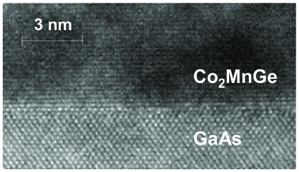
After the growth of the LED structures, the samples were transferred under ultra-high vacuum ( torr) to a second MBE system where a 7 nm thick Co2MnGe film was grown at 175 ∘C, followed by a 2.5 nm thick Al capping layer used to prevent oxidation in air. Streaky and sharp in-situ reflection high-energy electron diffraction (RHEED) patterns were observed during Co2MnGe growth, indicating that the films are single crystal with smooth surfaces. The spacing and intensities of the RHEED streaks suggest that Co2MnGe grows in the (001) orientation and an L-like crystal structure XYDong . The high-resolution cross-sectional transmission electron microscopy (TEM) image in Fig. 1 indicates an abrupt coherent Co2MnGe/GaAs interface. TEM diffraction shows that the film is L-like with small disordered B2-like regions. X-ray diffraction revealed that the films are pseudomorphic with an out-of-plane lattice parameter of 5.86 Å.
Au contacts were deposited by a shadow mask technique, and then the samples were processed into 300 m diameter circular mesas using standard photolithography and both dry and wet chemical etching. The devices were then annealed in N2 at 250 ∘C for one hour. Electroluminescence (EL) measurements were carried out with a bias voltage applied between the substrate and the Co2MnGe contact as shown in the inset of Fig. 2. Light was collected along the growth direction, which was parallel to the magnetic field. For the QW detector of sample I, the EL was dominated by recombination of heavy-hole excitons in the QW. The EL was measured for both circular polarizations and integrated over a window 3 meV wide around the heavy-hole exciton peak. The EL polarization was then calculated from the integrated intensities for right and left circularly polarized light. The EL spectrum for sample II was due to band-edge recombination in the -GaAs substrate, and in this case the intensities were integrated over a window 40 meV wide around the EL maximum. The electron spin polarization in the detector is , where for sample I and for the bulk detector of sample II OO .
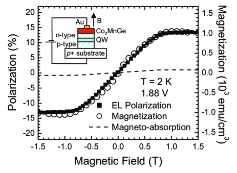
The EL polarization measured for sample I at 2 K and a bias of 1.88 V is shown in Fig. 2 as a function of the applied magnetic field. The magnetization measured in the same geometry is also shown. As is evident from Fig. 2, the magnetization and the EL polarization show nearly identical magnetic field dependence. They both saturate at a field of 0.8 T, above which reaches a maximum value of approximately 14 %. The magneto-absorption of the Co2MnGe film measured in a transmission experiment is shown as the dashed curve in Fig. 2 and is less than 1 %, approximately half the value for Fe films of comparable thickness. After subtraction of the magnetoabsorption from the raw data, the steady-state spin polarization in the QW is 13 % at 1 T.
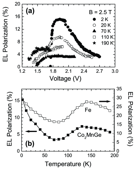
The field dependence of in Fig. 2, which follows the magnetization nearly exactly, is one of the explicit signatures of spin injection. A second distinguishing feature of spin injection into -- junction detectors is a marked dependence of on the bias voltage and temperature, which influence the recombination and spin relaxation rates in the QW Adelmann . EL polarization data measured for sample I as a function of bias at several different temperatures are shown in Fig. 3(a). The magnetic field for this set of measurements was fixed at 2.5 T, which is above the saturation field of Co2MnGe. The significant features of these data, including the maximum as a function of bias at low temperatures and the pronounced suppression of the signal near 70 K, are similar to those found in bias-dependent measurements on Fe/(Al,Ga)As spin LEDs Adelmann . The spin detector used in these measurements is of the same design as in Ref. Adelmann, , in which the bias dependence of the was demonstrated to depend strongly on the recombination and spin relaxation times in the quantum well. Additional evidence that the detector plays a critical role can be seen in Fig. 3(b), which shows the maximum polarization signal measured at each temperature for both Co2MnGe and Fe. The minimum in at 70 K and the maximum near 150 K appear for both injector materials. As discussed in Ref. Adelmann, , the existence of the minimum at 70 K is due to a crossover from a low-temperature regime in which excitonic effects dominate to a high-temperature regime in which the electrons in the QW are essentially free, and the spin relaxation rate is reduced. Although the magnitude of the signal in Co2MnGe is smaller, the overall behavior observed in Fig. 3(b) is very similar for the two materials. The two important differences are the smaller overall signal for Co2MnGe (15 % as opposed to 28 % for Fe) as well as the stronger decrease in between 2 and 70 K.
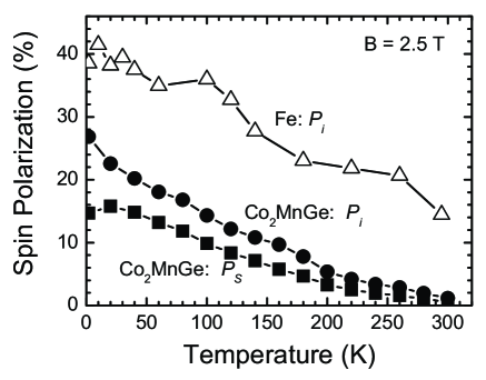
Given the similarities between the data obtained using Fe and Co2MnGe injectors, it is reasonable to ask whether the differences observed at the lowest temperatures in Fig. 3(b) are significant. Addressing this question requires a calibration of the semiconductor spin detector, which is accomplished by measuring the spin detection efficiency , where and are the recombination and spin relaxation times for electrons in the QW OO . Once is known, the injected spin polarization can be calculated. In principle, can be determined from the optical Hanle effect in a transverse magnetic field Motsnyi . In practice, the recombination time for QW detectors increases rapidly with temperature and depends strongly on bias, making a reliable calibration difficult. However, for bulk detectors such as sample II, the full Hanle curve can be measured up to room temperature, therefore allowing for a reliable determination of at all temperatures. The measured spin polarization for sample II (corrected for magnetoabsorption) is shown in Fig. 4 using solid squares, and the injected polarization deduced from the Hanle calibration is shown using solid circles. For comparison, obtained with an Fe injector on an otherwise identical device is shown using open triangles. The injected spin polarization for Co2MnGe reaches a maximum of 27 % at 2 K, in contrast to the value of 40 % reached with an Fe injector. More significantly, as suggested by the raw polarization measurements in Fig. 3(b), the spin polarization injected from Co2MnGe decreases more rapidly with increasing temperature than in Fe. In the case of Fe, the injected polarization is approximately 15 % at room temperature. In contrast, the injected polarization at 300 K is negligible for the Co2MnGe device, in spite of the fact that room temperature is still well below the Curie temperature of 905 K Cheng .
The injected polarization for Co2MnGe is therefore significantly below the value of 100 % that would be expected for a half-metal and shows stronger temperature dependence than observed for spin injection from Fe. Although the interpretation of absolute polarization measurements made using a spin-LED is subject to challenge, the injected polarization measured for Co2MnGe is smaller than that for Fe as determined using both QW and bulk detectors. Given the small gap ( meV) predicted for minority spins in Co2MnGe Picozzi1 and some evidence for disordered (B2-like) regions in TEM, the apparent absence of half-metallic behavior is not too surprising and is consistent with earlier conclusions based on point-contact Andreev spectroscopy of bulk samples Cheng . Heusler alloys with a larger minority spin gap, such as Co2MnSi Ishida ; Schmalhorst , may be more effective injectors. Furthermore, the spin injection experiment described in this letter probes the polarization at the interface between a thin film of Co2MnGe and Al0.1Ga0.9As. In addition to considering the electronic structure of the interface Galanakis , a realistic theory will also have to incorporate the presence of alloy disorder in the film as well as the effects of non-zero temperature. These factors will play an essential role in interpreting spin injection measurements on new materials.
This work was supported in part by the DARPA SPINS program, ONR, and the University of Minnesota MRSEC (NSF DMR-0212032).
References
- (1) R. Fiederling, M. Kelm, G. Reuscher, W. Ossau, G. Schmidt, and A. Waag, Nature 402, 787 (1999); D.K. Young, B. Beschoten, F. Matsukura, H. Ohno, and D.D. Awschalom, Nature 402, 790 (1999).
- (2) H.J. Zhu et al., Phys. Rev. Lett. 87, 016601 (2001); A.T. Hanbicki et al., Appl. Phys. Lett. 80, 1240 (2002); V.F. Motsnyi et al., Appl. Phys. Lett. 81, 265 (2002); X. Jiang et al., Phys. Rev. Lett. 90, 256603 (2003); J. Strand et al., Phys. Rev. Lett. 91, 036602 (2003).
- (3) A.T. Hanbicki et al., Appl. Phys. Lett. 82, 4092 (2003).
- (4) S. Ishida, T. Masaki, S. Fujii, and S. Asano, Physica B 245, 1 (1998).
- (5) R.A. de Groot, F.M. Mueller, P.G. van Engen, K.H.J. Buschow, Phys. Rev. Lett. 50, 2024 (1983).
- (6) P.J. Webster, J. Phys. Chem. Solids 32, 1221 (1971).
- (7) T. Ambrose, J.J. Krebs, and G.A. Prinz, Appl. Phys. Lett. 76, 3280 (2000).
- (8) J.W. Dong, L.C. Chen, C.J. Palmstrøm, R.D. James, S. McKernan, Appl. Phys. Lett. 75, 1443 (1999).
- (9) X.Y. Dong, J.W. Dong, J.Q. Xie, T.C. Shih, S. McKernan, C. Leighton, and C.J. Palmstrøm, J. Cryst. Growth 254, 384 (2003).
- (10) M.S. Lund, J.W. Dong, J. Lu, X.Y. Dong, C.J. Palmstrøm, and C. Leighton, Appl. Phys. Lett. 80, 4798 (2002).
- (11) R.J. Soulen, Jr., J.M. Byers, M.S. Osofsky, B. Nadgorny, T. Ambrose, S.F. Cheng, P.R. Broussard, C.T. Tanaka, J. Nowak, J.S. Moodera, A. Barry, and J.M.D. Coey, Science 282, 85 (1998).
- (12) J. Schmalhorst, S. Kämmerer, M. Sacher, G. Reiss, A. Hütten, and A. Scholl, Phys. Rev. B 70, 024426 (2004).
- (13) S.F. Cheng, B. Nadgorny, K. Bussmann, E.E. Carpenter, B.N. Das, G. Trotter, M.P. Raphael, and V.G. Harris, IEEE Trans. Magn. 37, 2176 (2001).
- (14) S. Picozzi, A. Continenza, and A.J. Freeman, Phys. Rev. B 66, 094421 (2002); I. Galanakis, P.H. Dederichs, and N. Papanikolaou, Phys. Rev. B 66, 174429 (2002).
- (15) I. Galanakis, J. Phys. Cond. Matt. 14, 6329 (2002); S. Picozzi, A. Continenza, and A.J. Freeman, J. Appl. Phys. 94, 4723 (2003).
- (16) P.A. Dowben and R. Skomski, J. Appl. Phys. 93, 7948 (2003).
- (17) Optical Orientation, edited by F. Meier and B.P. Zakharchenya (North-Holland Physics Publishers, New York, 1984).
- (18) C. Adelmann, X. Lou, J. Strand, C.J. Palmstrøm, and P.A. Crowell, cond-mat/0409103.
- (19) V.F. Motsnyi, P. van Dorpe, W. van Roy, E. Goovaerts, V.I. Safarov, G. Borghs, and J. de Boeck, Phys. Rev. B 68, 245319 (2003).