Electric response of DNA hairpins to magnetic fields
Abstract
We study the electric properties of single-stranded DNA molecules with hairpin-like shapes in the presence of a magnetic flux. It is shown that the current amplitude can be modulated by the applied field. The details of the electric response strongly depend on the twist angles. The current exhibits periodicity for geometries where the flux through the plaquettes of the ladder can be cancelled pairwise (commensurate twist). Further twisting the geometry and changing its length causes complex aperiodic oscillations. We also study persistent currents: They reduce to simple harmonic oscillations if the system is commensurate, otherwise deviations occur due to the existence of closed paths leading to a washboard shape.
pacs:
85.64.+h, 73.23.-b, 05.60.GgIntroduction.— Recently, conduction properties of molecules have been intensely investigated. This has been fueled by a strong motivation to replace semiconductors with molecules that can save manufacturing expenditure due to their self-assembly properties. One of the significant steps towards molecule-based electronic devices has been made through DNA conduction measurements. Superconductivity was observed, but was supposed to be due to the proximity effect of the superconducting leads kasumov . A random base sequenced DNA was shown to behave as an insulator pablo , whereas the homogeneous poly(G)-poly(C) molecule have a large gap in their current-voltage (IV) characteristics porath . Also, Ohmic behavior of DNA ropes was studied by Fink et al. fink .
On the other hand, in small systems where the phase coherence of electrons can be maintained, quantum interferences play a key role in determining the characteristic properties. Indeed, a large number of devices that have been proposed, such as switches and transistors, are based on the wave nature of electrons alamo . One way to observe the interferences in a controllable way is to apply a magnetic field. It comes into play when the systems can accommodate non-simply-connected paths; the presence of the flux tube gives a phase shift in the wave packet of the particle and changes the interference patternAB .
Despite abundant literature on DNA conduction, less attention has been paid to the existence of interference effects in this system. Molecules however have a huge variety in their structures allowing for different interference events. For instance, in a double stranded DNA, base pairs wind about the helical axis, which can be modelled as electrons travelling on a twisted ladder-like structure. When a magnetic flux is present, there exist trajectories enclosing a finite flux, which may affect the physical properties of the system. Furthermore, if one considers single stranded DNA or RNA, one may observe even more interesting geometries with loops and bulges.
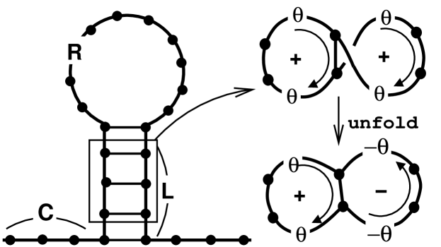
The purpose of this paper is to elucidate the effects of interference on the electronic properties of these molecules. As a minimal model, we consider a hairpin-like structure in the presence of a magnetic flux, as depicted in Fig. 1. The bases are coupled to each other via electron hopping and Coulomb repulsion. For simplicity, we consider them as identical except for the hopping constants. We evaluate the currents through the structures when they are coupled to electron reservoirs. The magnetic flux applied to the system is shown to modify the current amplitude. It is also shown that the characteristics depend on the twist angles. For a geometry where the fluxes through the plaquettes of the ladder are cancelled pairwise (we refer to it as commensurate ladder), the current oscillates as a function of the flux through the loop in units of flux quantum , with period , as in a single-loop openring . Twisting the geometry or changing its length changes the periodic oscillation into complex aperiodic ones. We have also evaluated the persistent currents (PC) of the system pc which with a commensurate ladder behaves as that of a single loop. For an incommensurate ladder, non-vanishing contributions are built-up by the closed paths embracing the ladder, leading to washboard-shaped PC.
System.— We assume that the system is described by a Hubbard-type model for spinless fermions yi :
| (1) |
where with the operator annihilating the Fermionic particle at site , and the sum is over the nearest neighboring pairs. This effective Hamiltonian was used to explore the conductance gap observed in the experiments of ref.porath and the gapless states in the engineered DNA mdna . Partitioning the hairpin into C(hain), L(adder), and R(ing) sectors (see Fig. 1), we assign the hopping parameters along the contour as follows:
In addition, the ring hoppings in the ladder are characterized by
| (2) |
and with and satisfying with the number of sites in the chain, the ladder, and the ring, respectively.
Here the phases accompanying the hopping integral are due to the presence of the threading flux and are defined as with . For our system, the phase factor in the ring takes a simple form as with measuring the total flux through the ring in units of the flux quantum . The magnetic flux penetrating the unit cell in the ladder introduces the phase factor given by
| (3) |
where is the effective path length between bases, is the factor accounting for the area variation along the sites due to the twist of base:
| (4) |
and is the twist angle that can be varied from sample to sample, for example, by changing the amount of added gyrase during preparation. Relating the magnetic fluxes through the loop and the unit cell of the (flattened) ladder through the area ratio , we define .
Let us consider the case of strong Coulomb repulsion where the ground state of the system at half-filling contains charge density waves . At low temperature (), one can safely consider the mean-field version of the Hamiltonian
| (5) |
where the renormalized strength of the repulsion is given by . Therein, we have made the asumption that the repulsion between bases in pair in the ladder is negligible and is constant over the system. If this is not the case, an intricate point arises; specifically, when is odd, the density waves must be distorted and have abrupt spatial changes in , giving rise to a kink (or a soliton). The existence of kinks and their dynamics in an odd-numbered ring can be another problem of interest. However,for the sake of simplicity, we leave it for future studies.
Transmission and currents—Let us now study the physical properties of the system by evaluating its electric conductance. To this end, we consider electrodes coupled to the system as in Fig. 1, introducing the self-energy correction on the edges of the chain as
| (6) |
There is in fact some energy dependence in but considering the bulky electrodes mostly used in experiments, we regard it as energy independent and identical for both electrodes. Evaluation of the Green function of the system, , leads to the transmission coefficient from the left to the right lead as fisherlee
| (7) |
where the coupling matrices are given by . The corresponding currents driven by the finite voltage bias are obtained by the Landau-Büttiker formula landauer
| (8) |
where is the Fermi-Dirac distribution function, and are the chemical potential of the left and right leads respectively, the difference of which is controlled by the applied bias voltage as .
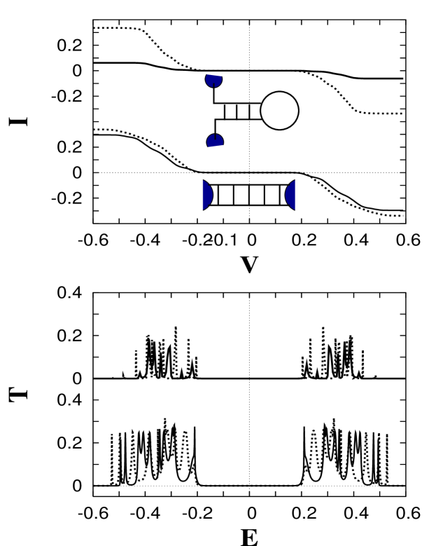
Figure 2 displays transmissions and currents for the two configurations (see the upper panel), the ladder and the hairpin with their ends coupled to external leads. The transmission windows for the hairpin gets narrower than that for the ladder, due to the smaller number of bonds. For the ladder, when magnetic fields are absent, the IV curve agrees with the IV characteristics for the homogeneous poly(G)-poly(C) molecules with a large gap porath . When a magnetic field with a strength is applied, the current is suppressed. This is also the case for the hairpin, with a different degree of suppression.

To see how the magnetic field alters the current amplitude, let us fix the voltage bias, for example, eV and eV for the hairpin configuration of Fig. 2. Figure 3 (a) demonstrates how the corresponding currents oscillate with varying flux. Here we present three curves for a given voltage, each one for a different twist angle. The interesting feature is that for (solid lines) the oscillation is periodic with period . On the other hand, oscillations are not complete even until for the case (dotted lines) and (dot-dashed lines). One can also notice that for , the current dips are located at the multiples of . Taking other twist angles moves the dips. This twist-angle dependence can be understood as follows: Consider the area factor . The flux through a closed path in the ladder is given by . For the hairpin configuration (), every path has its respective counter path in such a way that pairwise cancellation of the flux occurs since . Consequently, the flux through the ladder gives null effects. In that case, in terms of the magnetic flux, the geometry is topologically equivalent to that of a single loop connected to the electron reservoirs (see Ref. openring ): The transmission of this configuration has been shown to oscillate with period . When twisting the structure slightly out of the commensurate configuration (for example, ), such a perfect cancellation does not occur, leading to complex aperiodic oscillations (within the flux interval). One can also expect that adding more plaquettes must yield similar features. In Fig. 3 (b) and (c), doubling the size of the ladder, we plot the currents at eV. Neither of the twist angles leads to periodicity. Also, the current enhancement by finite flux can be noticed. Let us here give an order of magnitude of the strength of the magnetic field for the effects to be measurable. For small loops with radius (corresponding approximately to 8 bases), in order to achieve , one needs fields in the range of thousands of Tesla. Considering that at present the maximum field strength is about 100 Tesla magfield , it would be easier to realize a larger loop. In Fig. 3 (c), we take 24 bases in the loop, making the area about ten times bigger than that in Fig. 3(a). Even if the field strength can be in the realizable range, the effects remain still significant and are not washed out by the enlarged loop-size.

Persistent currents— Now we evaluate the persistent currents when the system is isolated. This allows to assess how much the magnetic fields alter the energy levels (whereas the magnetic-flux effect demonstrated above mixes the influence on wavefunctions and on the energy spectrum). This becomes clear when writing the Green function in an expansion of eigenfunctions:
| (9) |
leading to the transmission coefficient given in Eq. (7): Here the magnetic flux affects not only the energy spectrum but also the wavefunction . Let us take a simple example for understanding persistent currents. Consider a ring of radius threaded by a flux (in units of the flux quantum ). The angular momentum of free electrons traveling on the ring is shifted by the magnetic flux as with denoting the expectation value of an operator in the th eigenstate. The energy eigenvalues are then given by . At zero-temperature, the evaluation of currents in the ground state is straightforward
| (10) |
where is the velocity operator, and the sum is over all the occupied levels, for an even number of electrons and for odd . It is clear that the ground state carries currents so that if dissipation is absent in the system, the currents keep flowing, and are thus named persistent currents. The currents oscillate with the magnetic flux with a period of , and their amplitudes decrease as . When band gaps are present in the system (due for example to Coulomb repulsion or coupling to lattice distorsion), the persistent currents are suppressed exponentially with increasing loss . In this case, one has
| (11) |
with for vanishing gap. Here the sign of the current depends on the parity of pc ; loss .
Our system (a loop coupled to a ladder) has a number of closed paths or rings, with different areas and sizes. There are contributions of persistent currents from all the rings, and therefore, , where denotes the current flowing in the -th ring of size , enclosing the flux . We first evaluate the persistent currents in the hairpin with and where the magnetic fluxes through the ladder plaquette effectively cancel one another (see the upper panel in Fig. 4). The currents behave as those of a single loop; note that the sign of the current changes with the parity of (we consider half-filled systems). Furthermore, increasing the number of bases decreases the current amplitude. Following the finite size scaling in Eq. (11), all the curves are shown to be merged into a single one (see the inset). Adding more plaquettes causes a deviation from a single-component sinusoidal-curve (see the upper panel in Fig. 4). Since larger rings die out exponentially , taking paths enclosing up to two unit-cells, one obtains the approximate form of the currents as
| (12) |
where is the flux through the th plaquette of the ladder, and is the sum of two neighboring ’s. For hairpins with a few plaquette in the ladder, Eq. (12) perfectly fits the numerical evaluations (obviously, for a hairpin with a single plaquette, the above expression is exact).
Summary and Remarks— We have demonstrated how a magnetic flux could influence the electronic properties of molecules with a twisted hairpin-like shape. The current has been shown to oscillate with flux changes. Geometry factors such as twist angles and the number of rungs of the ladder play a crucial role in determining oscillation patterns. We point out that there exists geometries where the flux through the ladder vanishes, so that the sole cause for the oscillation is the flux through the loop. For that case, the current of the ladder ressembles that of a ring. Twisting the geometry brings about complex aperiodic oscillations. These oscillations are also reflected on persistent currents. The non-vanishing contributions of the closed paths embracing the ladder leads to washboard-shaped persistent currents.
We should note that the above mentioned results were predicted under the assumption that electrons preserve their initial phase in their propagation. Therefore, maintaining phase coherence is crucial in experimental observations of these phenomena. The phase coherence is strongly affected for example by temperature (or generally speaking, coupling to the environmental degrees of freedom). For DNA molecules for which conduction properties are measured at room-temperature, phase coherence can still be traced. However, finite-temperature effects cause fluctuations in the structure. Even if the effect is small, the plaquette areas as well as the phases due to the flux become randomized. This addresses the issue of (weak) localization that will be considered in a future work.
References
- (1) A. Kasumov, M. Kociak, S. Guéron, B. Reulet, V. Volkov, D. Klinov, and H. Bouchiat, Science 291, 280 (2001).
- (2) P. de Pablo, F. Moreno-Herrero, J. Colchero, J. Gómez-Herrero, P. Herrero, A. Baró, P. Ordejón, J. Soler, and E. Artacho, Phys. Rev. Lett. 85, 4992 (2000).
- (3) D. Porath, A. Bezryadin, S. de Vries, and C. Dekker, Nature (London) 403, 635 (2000).
- (4) H.-W. Fink and C. Schönenberger, Nature (London) 398, 407 (1999).
- (5) J. A. del Alamo and C. C. Eugster, Appl. Phys. Lett. 56, 78 (1990); F. Sols, M. Macucci, U. Ravaioli and K. Hess, J. Appl. Phys. 66, 3892 (1989); T. Palm and L. Thylén, Appl. Phys. Lett. 60, 237 (1992).
- (6) Y. Aharonov and D. Bohm, Phys. Rev. Lett. 115, 485 (1959).
- (7) Y. Gefen, Y. Imry, and M. Ya. Azbel, Phys. Rev. A 30, 1982 (1984); M. Büttiker, Phys. Rev. B 32, 1846 (1985); A. M. Jayannavar and P. Singha Deo, Phys. Rev. B. 51, 10175 (1995).
- (8) M. Büttiker, Y. Imry, R. Landauer, Phys. Lett. A 96, 365 (1983); H.-F. Cheung, Y. Gefen, E. K. Riedel, and W.-H Shih, Phys. Rev. B 37, 6050 (1988).
- (9) J. Yi, Phys. Rev. B 68, 193103 (2003).
- (10) A. Rakitin, P. Aich, C. Papadopoulos, Yu. Kobzar, A. S. Vedeneev, J. S. Lee, and J. M. Xu, Phys. Rev. Lett. 86, 3670 (2001).
- (11) D. S. Fisher and P. A. Lee, Phys. Rev. B 23, R6851 (1981).
- (12) R. Landauer, IBM J. Res. Dev. 1, 223 (1957); J. Math. Phys. 37,5259 (1996); S. Datta, Electronic Transport in Mesoscopic Systems (Cambridge University Press, Cambridge, 1999).
- (13) J. Sims, A. Baca, G. Boebinger, H. Boenig, H. Coe, K. Kihara, M. Mauzo, C. Mielke, J. Schillig, Y. Eyssa, B. Lesch, L. Li and H. Schneider-Muntau, IEEE Trans. Appl. Supercond. 10, 510 (2000).
- (14) D. Loss, Phys. Rev. Lett. 69, 343 (1992); J. Yi, M. W. Cho, S. H. Salk, Phys. Rev. B 65, 193108 (2002).