Present address: ]IBM Research - Zurich Research Laboratory, 8803 Rüschlikon, Switzerland
Angular-dependence of magnetization switching for a multi-domain dot: experiment and simulation
Abstract
We have measured the in-plane angular variation of nucleation and annihilation fields of a multi-domain magnetic single dot with a micro-SQUID. The dots are Fe/Mo(110) self-assembled in UHV, with sub-micron size and a hexagonal shape. The angular variations were quantitatively reproduced by micromagnetic simulations. Discontinuities in the variations are observed, and shown to result from bifurcations related to the interplay of the non-uniform magnetization state with the shape of the dot.
pacs:
Valid PACS appear hereCoherent rotation of magnetization is the simplest model of magnetization reversal, proposed by Stoner and Wohlfarth in 1948bib-STO48 . Coherent rotation predicts the value of the switching field of a single-domain system as a function of the direction of the external field . For a two-dimensional system with uniaxial anisotropy the polar plot falls on the well-known astroidbib-SLO56 . The full experimental proof for coherent rotation was given only recently, when nanoparticles of high quality and of size small enough to roughly satisfy the hypothesis of uniform magnetization could be investigated individuallybib-WER97 ; bib-BON99 . Starting from this proof, it is now a challenge to understand magnetization reversal in increasingly large (and thus complex) systems. The simplest ingredient to add to coherent rotation is to allow minor deviations from strictly homogeneous magnetization. The consequences on magnetization processes were addressed by numerical micromagneticsbib-SCH88 , investigated analyticallybib-COW98b and checked experimentallybib-COW98c . The next step is now to tackle quantitatively more strongly non-uniform systems, those that may display magnetic domains and domain wallsbib-HUB98b . In such systems a switching field is not the signature of the full reversal of magnetization, but instead reflects events like nucleation, propagation and annihilationbib-WER96c . Few and only partial experimentalbib-WER96c and numericalbib-WEI02 reports are found on this issue. A more detailed study would open the door to understanding microscopic details of magnetization reversal processes in macroscopic materials. In this Letter we present such a study in a model system: sub-micrometer Fe faceted dots self-assembled in UHV, that have a high structural quality and display simple multi-domain statesbib-FRU01b ; bib-FRU03c . The angular dependence of the ’s of a single dot was studied with the micro-SQUID techniquebib-WER01 . This can be seen as the first experimental generalization of astroids for an individual multi-domain system. A striking feature is the occurrence of discontinuities (hereafter named jumps) in plots. These jumps were reproduced and understood with the help of numerical micromagnetism. They result from bifurcations, related to the interplay of the non-uniform magnetization with the shape of the dot. This also shows that a complex behavior does not necessarily result from defects, whose role may have been overestimated in the literature of magnetic dots made by lithography.
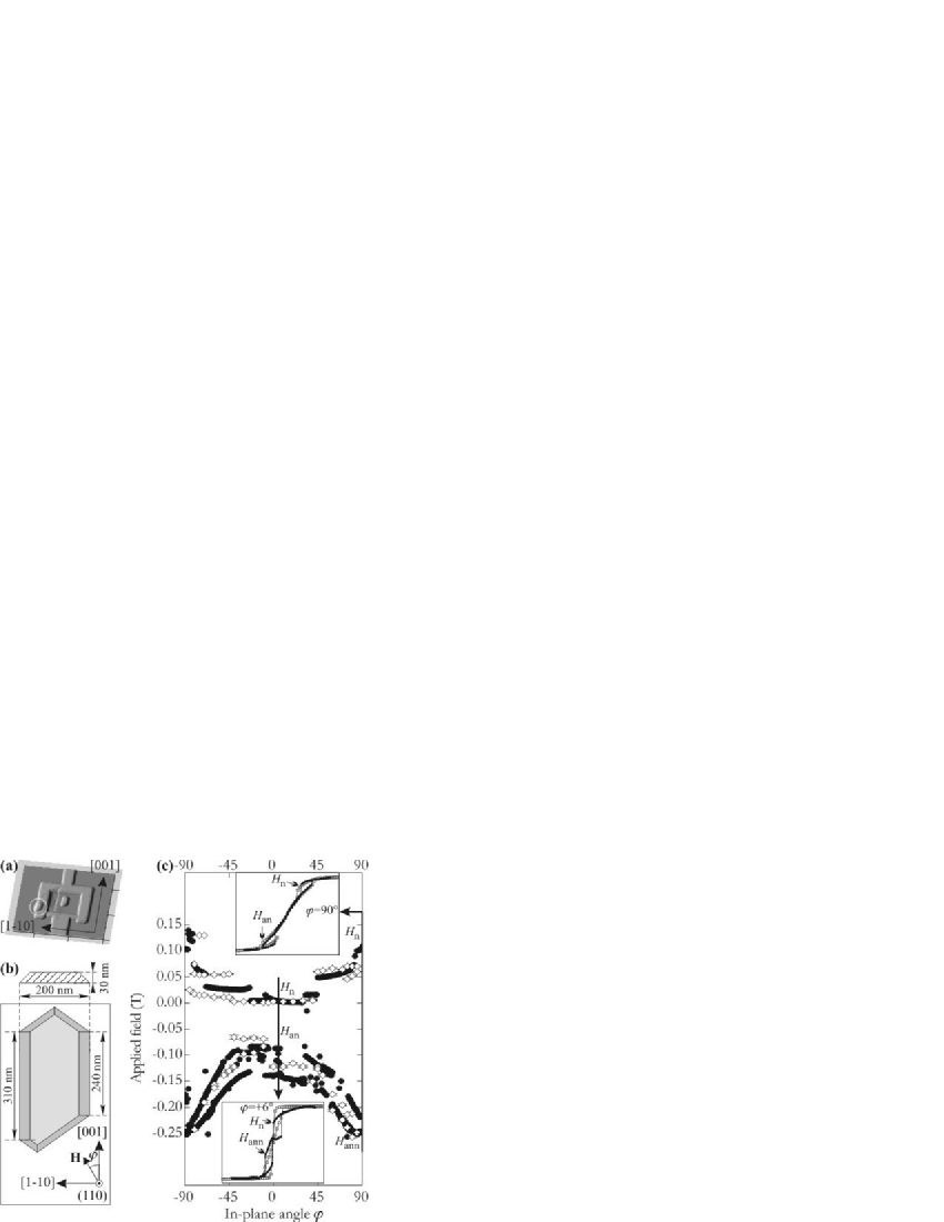
The Fe(110) epitaxial dots were fabricated with pulsed laser deposition in ultra-high vacuum by self-assembly on . The dots display the shape of ingots with atomically-flat facets, bulk lattice parameter and bulk cubic magneto-crystalline anisotropy favoring axes, however of magnitude much smaller than bib-FRU01b . The inter-dot dipolar fields are negligible with respect to . The remanent state consists of flux-closure domains, resulting from demagnetizing fields within each dotbib-FRU03c . Such domains can occur due to size of the dots being well above the exchange length bib-FRE57 ; bib-KRO62 . The in-plane ’s of a single Fe dot were measured below using the micro-SQUID techniquebib-WER01 . For these measurements, the dots were covered in UHV by Mo, followed by (then 12 hours air-oxidized), and a tri-layer. Arrays of square micro-SQUIDs with edge were patterned by e-beam lithography and reactive ion etching of the tri-layer. The oxidized Al layer prevents ferromagnetic-superconductor proximity effects between the dots and the micro-SQUIDs. Although the dots are randomly distributed on the surface, their large number yields a significant probability to find one suitably coupled to a micro-SQUID. The location and shape of the single dots under investigation were checked a posteriori by AFM. The size of the dot selected here (Figure 1a) is (Figure 1b). Micromagnetic simulations were performed for (no thermal activation) using custom-developed codes, either based on integrating the LLG equation in a finite differences code (rectangular prisms)bib-TOU02 or on energy minimization in a finite elements code (tetrahedra)bib-HER01 . The applied field was increased step-wise in hysteresis loops. In finite differences the sample was divided into cells with uniform lateral and vertical size and , respectively. For finite elements tetrahedra of irregular but similar shape were used, with a maximum (resp. minimum) volume of (resp. ). We set , and in the calculation.
In the following we call the angle between the in-plane and the in-plane long axis of the dot (Figure 1b). Due to a shape effect, in-plane () is a magnetically-harder direction than . The insets of Figure 1c show micro-SQUID hysteresis loops for two angles (). Such loops with negligible remanence although with significant hysteresis, are characteristic of multidomain systems with a limited number of domains. Starting from positive saturation the first , named hereafter , is expected to reveal a nucleation event, e.g. the entry of a magnetic vortexbib-GUS01b in the dot. The second , occurring at negative fields and named , is expected to reveal an annihilation event, i.e. the expulsion from the dot of a previously-nucleated vortex or wall. Figure 1c shows the experimental angular variation and . The two-fold symmetry results from the elongated shape of the dot. Two striking features are observed, that shall be explained in the course of the discussion. First, jumps of both and occur at some angles. Second, depending on the range of angles, one or two and/or are observed.
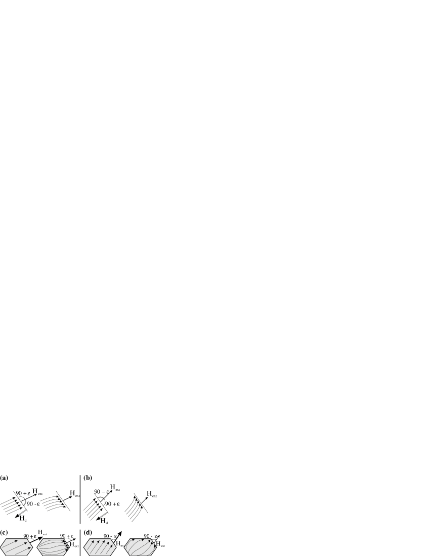
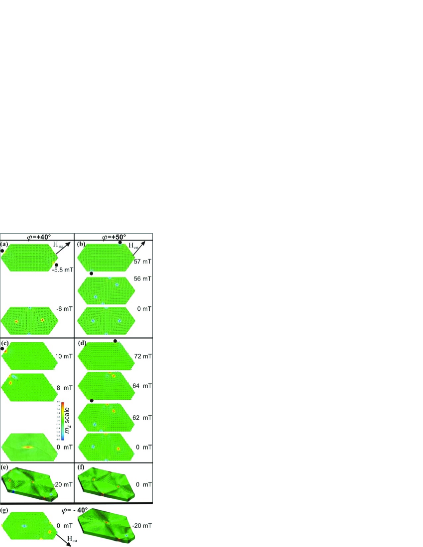
The jumps of can be understood qualitatively by simple arguments. Let us sketch in a quasistatic picture the evolution of magnetization close to an edge during the first stages of a hysteresis loop (Figure 2a-b). Starting from saturation, upon decrease of the relative importance of the dipolar energy increases. As a result progressively rotates towards the edge to reduce surface charges, and thus reduce . The direction of rotation, clockwise or anticlockwise, depends on the initial direction of with respect to the normal to the edge (imposed by the direction of ), due to the torque exerted by the dipolar field on . With this picture at least two different slightly inhomogeneous magnetization states, so-called ’leaf states’bib-COW98b , are expected to appear upon decrease of , e.g. when starting from saturation along or (Figure 2c-d). Bifurcation must occur for at least one intermediate angle between these two paths. Then, it is obvious that for applied on either side of this angle, the magnetization pattern will evolve towards very different states, each characterized by a different entry point for vortices–and thus of edge orientation, explaining a jump in . These ideas were confirmed by micromagnetic simulation. In a first attempt the simulations were performed on a dot with vertical facets and symmetric ends. Figure 3a-b shows the static magnetization states just before and after . For , before the state belongs to the class sketched in Figure 2c, as expected. Then two regions of strongly non-uniform magnetization develop simultaneously, ending up in the entry of two vortices at . As is further decreased the two vortices with opposite circulation move towards the inner part of the dot, ending up in a diamond state (Figure 3a). For the state before nucleation looks like that in Figure 2d. The loci of the entering vortices are thus modified with respect to the above situation, explaining the jump of , but ending as well in a diamond state, i.e. with two vortices (Figure 3b).
The above arguments explain the jumps of , but fail to explain (1) the existence of either one or two and for some angles (Figure 1c) (2) the experimental observation of both diamond and Landau statesbib-FRU03c , i.e. with two or one wall or vortex. Indeed in the simulations for any two vortices appear simultaneously on opposite loci, as the dot was assumed to be perfectly symmetric. Due to the large dot size these vortices interact weakly with each other, thus both enter the dot, ending up in a diamond state. In order to refine our interpretations, we now report simulations performed on dots with a slightly asymmetric shape, similar to that of the AFM observation of the measured dot (Figure 1a). Opposite loci are no more equivalent due to the point-reversal symmetry breaking. Two situations occur. If opposite loci are similar two vortices still enter the dot, one slightly before the other in terms of , however still ending in the diamond state (e.g. for Figure 3d). If opposite loci are significantly different, then one of the vortices may enter the dot at a much higher field than the other. It then moves towards its centre, delaying and possibly preventing the entry of a second main vortex. This ends up in a Landau state (e.g. for , Figure 3d). Notice that the vortex may continuously change its shape into a Bloch wall, provided that the dot is long and thick enoughbib-HER99 ; bib-FRU03c . Thus, an asymmetric feature (like shape) is necessary to explain the experimental observation of one-wall/vortex statebib-FRU03c . Notice also that more vortices may appear depending on the detailed shape of the dot (Figure 3e,g). Figure 1c (upper part) shows that these simulations reproduce experimental convincingly. As a further step some simulations were performed in the finite-element scheme to avoid numerical roughness on the surfaces. This yielded results quantitatively similar to the case of vertical facets.
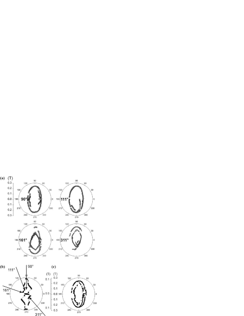
Simulations of (lower part of Figure 1c) also reproduce experimental data. The jumps of again result from the bifurcation before nucleation, implying different states before annihilation. The occurrence of one versus two may be associated with the occurrence of different flux-closure states at low field. A more general experiment consists in proceeding to nucleation with the field decreased along a given angle , followed by annihilation with the field increased along a different direction . The plot , measured while keeping fixed i.e. trying to prepare the system always in the same starting state, can be viewed as a signature of this state. Figure 4a displays such plots for several values of , chosen in different branches of the experimental (Figure 4b). The plots are not identical, which confirms that the remanent state depends on the angle of . The fact that different plots roughly consist of different parts of a common set of two branches is also easily understood. For a given a wall or a vortex of given circulation will always be pushed towards the same locus of the dot, be it alone at remanence (vortex or Landau state) or having a companion (diamond state). In the latter case one point is found on each branch, whereas in the former case only one branch is revealed.
Finally, the values of depend only weakly on the algorithm used (finite differences or finite elements). However, sometimes fine differences appear upon nucleation, such as the magnetization direction of vortices’ cores, or the occurrence of more than two vortices (see Figure 3, c versus e; d versus f; g), although both codes were benchmarked successfully one against each other on time-resolved magnetization reversal issuesbib-NIST4 . This underlines that describing the fine details of nucleation with simulations remains a challenge and that results should still be taken with care.
To conclude, we reported the measurements, quantitative reproduction and understanding of angular nucleation and annihilation fields and in a multi-domain magnetic particle. This is an example of a generalization to multi-domain states of the well-known Stoner-Wohlfarth astroid. The main feature is the occurrence of jumps in both plots, which result from the interplay of a non-uniform magnetization state with the shape of the dot. Thus, such jumps should not be automatically ascribed to defects when observed in experiments.
We thank Ph. David and V. Santonacci for technical support, and C. Meyer and W. Wulfhekel for critically reading the manuscript.
References
- (1) E. C. Stoner and E. P. Wohlfarth, Phil. Trans. Royal Soc. London A240, 599 (1948).
- (2) J. C. Slonczewski, Research Memo RM 003.111.224, IBM Research Center, Poughkeepsie, NY (unpublished).
- (3) W. Wernsdorfer, E. B. Orozco, K. Hasselbach, A. Benoit, B. Barbara, N. Demoncy, A. Loiseau, H. Pascard, and D. Mailly, Phys. Rev. Lett. 78, 1791 (1997).
- (4) E. Bonet-Orozco, W. Wernsdorfer, B. Barbara, A. Benoit, D. Mailly, and A. Thiaville, Phys. Rev. Lett. 83, 4188 (1999).
- (5) M. A. Schabes and H. N. Bertram, J. Appl. Phys. 64, 1347 (1988).
- (6) R. P. Cowburn and M. E. Welland, Phys. Rev. B 58, 9217 (1998).
- (7) R. P. Cowburn, A. O. Adeyeye, and M. E. Welland, Phys. Rev. Lett. 81, 5414 (1998).
- (8) A. Hubert and R. Schäfer, Magnetic domains. The analysis of magnetic microstructures (Springer, Berlin, 1999).
- (9) W. Wernsdorfer, K. Hasselbach, A. Sulpice, A. Benoit, J.-E. Wegrowe, L. Thomas, B. Barbara, and D. Mailly, Phys. Rev. B 53, 3341 (1996).
- (10) Z. H. Wei, C. R. Chang, N. A. Usov, M. F. Lai, and J. C. Wu, J. Magn. Magn. Mater. 239, 1 (2002).
- (11) P.-O. Jubert, O. Fruchart, and C. Meyer, Phys. Rev. B 64, 115419 (2001).
- (12) P. O. Jubert, J. C. Toussaint, O. Fruchart, C. Meyer, and Y. Samson, Europhys. Lett. 63, 135 (2003).
- (13) W. Wernsdorfer, in Advances in Chemical Physics, edited by I. Prigogine and S. A. Rice (Wiley, 2001), Vol. 118.
- (14) E. H. Frei, S. Shtrikman, and D. Treves, Phys. Rev. 106, 446 (1957).
- (15) H. Kronmüller, Z. Physik 168, 478 (1962).
- (16) J. C. Toussaint, A. Marty, N. Vukadinovic, J. Ben Youssef, and M. Labrune, Comput. Mater. Sci. 24, 175 (2002).
- (17) R. Hertel, J. Appl. Phys. 90, 5752 (2001).
- (18) K. Y. Guslienko and K. L. Metlov, Phys. Rev. B 63, 100403(R) (2001).
- (19) R. Hertel and H. Kronmüller, Phys. Rev. B 60, 7366 (1999).
- (20) NIST standard problem 4, see http://www.ctcms.nist.gov/mumag/mumag.org.html.