Modulating Unpolarized Current in Quantum Spintronics: Visibility of Spin-Interference Effects in Multichannel Aharonov-Casher Mesoscopic Rings
Abstract
The conventional unpolarized current injected into a quantum-coherent semiconductor ring attached to two external leads can be modulated from perfect conductor to perfect insulator limit via Rashba spin-orbit (SO) coupling. This requires that ballistic propagation of electrons, whose spin precession is induced by the Aharonov-Casher phase, takes place through a single conducting channel ensuring that electronic quantum state remains a pure separable one in the course of transport. We study the fate of such spin interference effects as more than one orbital conducting channel becomes available for quantum transport. Although the conductance of multichannel rings, in general, does not go all the way to zero at any value of the SO coupling, some degree of current modulation survives. We analyze possible scenarios that can lead to reduced visibility of spin interference effects that are responsible for the zero conductance at particular values of the Rashba interaction: (i) the transmitted spin states remain fully coherent, but conditions for destructive interference are different in different channels; (ii) the transmitted spins end up in partially coherent quantum state arising from entanglement to the environment composed of orbital degrees of freedom of the same particle to which the spin is attached.
pacs:
72.25.Dc, 03.65.Vf, 03.65.Yz, 73.23.-bI Introduction
Recent attempts in spintronics spintronics to harness electron spin for classical and quantum information processing have encountered two major challenges: efficient room temperature spin injection injection into a semiconductor and quantum-coherent control of spin states. kikkawa For example, a paradigmatic semiconductor spintronic device, the Datta-Das spin-field-effect transistor datta90 where current passing through a two-dimensional electron gas (2DEG) in semiconductor heterostructure is modulated by changing the strength of Rashba SO interaction via gate electrode, nitta requires both problems to be surmounted. The usage of the Rashba SO coupling (which arises due to inversion asymmetry of the confining electric potential for 2DEG) to control spin via electrical means has become one of the most influential concepts in semiconductor spintronics. injection The injected current can be modulated in this scheme only if it is fully polarized, while precessing spin has to remain quantum coherent during propagation between the two ferromagnetic electrodes. Although spin injection into bulk semiconductors has been demonstrated at low temperatures, ohno creating and detecting spin-polarized currents in high-mobility 2DEG has turned out to be a much more demanding task. In addition, the 2DEG region of spin-FET would be very sensitive to the stray fields induced by the ferromagnetic electrodes. johnson
For devices pushed into the mesoscopic realm, meso ; carlo_rmt it becomes possible to modulate even unpolarized currents by exploiting spin-dependent quantum interference effects in phase-coherent transport. This is due to the fact that at low temperature and at nanoscales full electron quantum state remains pure in the tensor product of orbital and spin Hilbert spaces, respectively. The conductors in the shape of multiply-connected geometries have been an essential playground since the dawn of mesoscopic physics meso ; webb to explore how quantum interference effects, involving topological quantum phases geo_phase acquired by a particle moving in the presence of electromagnetic potentials, leave signatures on the measurable transport properties. The typical example is a metallic ring in the magnetic field where transported electron encircling magnetic flux acquires Aharonov-Bohm topological phase which induced conductance oscillations. webb The electromagnetic duality entails an analogous effect—a neutral magnetic moment going around a charged line acquires Aharonov-Casher (AC) phase that can be manifested in a multitude of ways in mesoscopic transport quantities. entin ; marthur ; aronov ; su
In recently proposed spintronic ring device ring containing the Rashba SO coupling, the difference between AC phases of opposite spin states traveling clockwise and counterclockwise around the ring generates spin interference effects that can be observed in its transport properties. Since the ring conductance directly depends on this difference, ring ; diego such mesoscopic quantum interference effects can be exploited to modulate conductance of unpolarized charge transport through a one-dimensional (1D) ring (attached to two 1D leads) between 0 and by changing the Rashba electric field via gate electrode covering the structure. nitta The attractiveness of such all-electrical and all-semiconductor device comes from the fact that evades usage of any ferromagnetic elements or magnetic fields. However, its envisaged operation necessitates that quantum transport takes place through only a single Landauer conducting channel. carlo_rmt The theoretical analysis thus far has been confined to strictly 1D rings, ring ; molnar or 2D rings where only the lowest transverse propagating mode is open for quantum transport. diego In both of these cases of single-channel transport similar pattern of complete conductance modulation between 0 and is found, even though higher unoccupied modes in 2D rings can affect the lowest open channel. decoherence ; hausler
On the other hand, despite advances in nanofabrication technology, it is quite challenging to fabricate single channel quantum wires. When unpolarized current, consisting of both spin- and spin- electrons is injected through more than one propagating modes, defined by the transverse quantization in the leads of a realistic multichannel ring device, each channel will carry its own phase. Moreover, during quantum transport involving more than one conducting channel, any spin-independent scattering of charge (at interfaces or boundaries in the case of a clean system) subjected to SO coupling will lead to a loss of coherence of spin quantum state due to the possibility to entangle spin and orbital degrees of freedom (i.e., within the entangled state, spin subsystem cannot be described by a pure state spinor). decoherence The multichannel nature of quantum transport in realistic rings employed in experiments is also part of the controversy surrounding recent fundamental pursuits shayegan ; yang of the observable effect of spin Berry phase. The analysis of spin-dependent features in conductance oscillations as a function of the magnetic field in disordered rings is not as transparent as in the case of strictly 1D systems. yang The AC phase acquired by electrons propagating through the 1D ring, subjected to the Rashba electric field orthogonal to the ring plane (Fig. 1), was shown su to consist of a dynamical Rashba phase (which depends on the cycle duration) and the geometrical Aharonov-Anandan (AA) phase (which depends only on the path traced in the parameter space) characterizing any nonadiabatic cyclic evolution. geo_phase In the adiabatic limit, when spin becomes aligned with the effective momentum-dependent Rashba magnetic field in the reference frame of transported electron (Fig. 1), diego the AA phase becomes the spin-orbit Berry phase introduced in Ref. aronov, .
Here we address the problem of unpolarized current modulation in clean mesoscopic 2D rings with Rashba SO coupling by studying how the pattern of conductance oscillations changes as one opens conducting channels, one-by-one, for quantum transport. The paper is organized as follows. In Sec. II we discuss the issue of suitable Hamiltonian description of the ring with SO interactions. Then we introduce a model for the multichannel ring which makes it possible to efficiently implement realspin space Green function technique in order to obtain both the spin and the charge properties of coupled spin-charge transport. decoherence Section III studies the conductance modulation in strictly 1D rings as a function of the Fermi energy of the zero-temperature quantum transport. We also establish in this section the connection between the orientation of spin polarization vector and spin precession induced by the Rashba SO interaction, pointing out at spin-switch device properties of the AC rings when injected current is fully polarized. In Sec. IV we discuss conductance modulation in 2D rings with two and three open conducting channels. Although we find that the ring conductance, in general, is not diminished to zero in the multichannel transport at any strength of the SO coupling, it still displays oscillations as we tune the strength of the Rashba interaction. In order to relate such “incomplete” conductance modulation to spin interference effects of states which are not pure (but are instead described by the density matrices), we analyze in Sec. IV.2 transport through 2D rings within the picture of transmission eigenchannels. carlo_rmt This makes it possible to view the multichannel transport as if occurring through a set of “independent” 1D rings whose channels, however, can have complicated spin coherence properties. We conclude in Sec. V.
II Hamiltonian models for ring with Rashba Spin-Orbit interaction
In the absence of external magnetic field, the ballistic semiconductor ring structure subjected to the Rashba SO coupling is described by the following effective mass single-particle Hamiltonian
| (1) |
where is the vector of the Pauli spin operators, is the momentum vector in 2D space, and is the strength of the Rashba SO coupling. The last term represents the potential which confines electrons to a finite ring region within 2DEG. The analytical expressions for the ring conductance as a function of have been obtained only for a strictly 1D ring geometry—in this limit one can find the eigenstates of a closed ring and then compute the transmission coefficients by opening the ring to the attached leads where electrons are injected at the Fermi energy equal to the eigenenergies. ring ; diego ; molnar However, a search for the correct 1D ring Hamiltonian, which includes the Rashba interaction, has turned out to be an ambiguous task yielding several apparent solutions. For example, some of the recent studies have employed non-Hermitian Hamiltonians. aronov ; ring It was pointed in Ref. meijer, that performing the limit from 2D to 1D carefully, by taking into account the radial wavefunctions in the presence of narrow confinement, leads to a unique Hermitian single-particle Hamiltonian in cylindrical coordinates
| (2) | |||||
Here is the radius of the 1D ring, and is the angular coordinate. The last term in Eq. (2), which disappears if we simply take the radial coordinate in the cylindrical coordinate representation of the 2D Hamiltonian, is actually indispensable for this Hamiltonian to be a usual Hermitian operator corresponding to quantum observable.
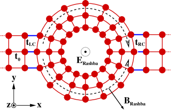
While the 1D Hamiltonian Eq. (2) provides a simplest starting point to study quantum transport through the ring within the Landauer-Bütikker transmission formalism, meso for efficient and numerically exact treatment of multichannel transport through finite width 2D rings attached to the leads it is advantageous to switch to a local orbital basis representation that makes is possible to employ realspin space Green function technique and obtain. decoherence Therefore, we introduce here a concentric tight-binding lattice Hamiltonian, composed of concentrically connected tight-binding ring chains, as sketched in Fig. 1. The two ideal semi-infinite leads with , of the same width as the ring itself, are attached symmetrically to the ring thereby breaking the rotational invariance of the closed ring problem. The case corresponding to a single ring chain, which represent a lattice version of the correct 1D Hamiltonian in Eq. (2), has frequently been employed to study the Aharonov-Bohm effect in mesoscopic ring-shaped conductors. abchain The case has appeared in the studies of the influence of finite ring width on the Aharonov-Bohm oscillations of magneto-conductance. aldea Here we introduce the Rashba SO interaction into the concentric tight-binding lattice with arbitrary number of ring chains. One of the advantages of our model over the conventional square lattice discretization of the finite width rings abring is that the width of the ring can be controlled precisely by varying the number of the ring chains one-by-one. This makes it possible to study the effects of multichannel transport systematically. The maximum number of open channels in a structure consisting of ring chains is equal to . The Hamiltonian corresponding to the set-up depicted in Fig. 1 contains five terms
| (3) |
The first term, which describes electrons in an isolated (i.e., closed to the environment) ring that are subjected to the Rashba SO coupling, is given by
| (4) | |||||
Here and are the lattice site indices along the azimuthal () and the radial () directions, respectively. The operator () annihilates (creates) a spin electron at the site of the ring. In our notation corresponds to the innermost ring chain, while stands for the outermost ring chain to which the external leads are attached. The operator () is identified with () due to the periodic boundary condition. In Eq. (3) is the on-site potential, while and are the nearest neighbor hopping energies along the radial and the angular directions, respectively. Those hopping energies have been generalized to include the SO coupling terms, which are given in the matrix form as
| (5) |
Here , , , , with being the lattice spacing constant along the radial direction, is the tight-binding SO coupling energy with being the SO coupling strength of the original Hamiltonian Eq. (1), and is the identity matrix. We further assume that the lattice spacing along the azimuthal direction in the outermost ring chain () is the same as that of the radial direction, such that . In order to avoid the negative value of (the radius of the innermost chain), the value of has to satisfy the condition .
In Eq. (3), the second term is the Hamiltonian for the left lead
| (6) |
where and are the lattice indices along the (current flowing) and the (transverse) directions, respectively. The operators () annihilate (create) spin electron at the site in the left lead. The Hamiltonian of the right lead has the same form as Eq. (6). Finally, the coupling between the leads and ring is described by the following Hamiltonians
| (7) | |||||
| (8) |
Here is the coupling strength between the left (right) lead and the ring. It is assumed that the left and the right lead are attached to the ring symmetrically, where we neglect the finite curvature of the outermost ring at the interface between the ring and the leads (this is justified if when the condition is satisfied).
Once the Hamiltonian Eq. (3) is given, one can evaluate the matrix of spin-resolved conductance by using the Landauer-Büttiker’s formula generalized to include the spin-degree of freedom
| (13) |
where is a transmission matrix element determining the probability amplitude that electron injected in orbital channel with spin in the left lead would end up in a conducting channel of the right lead with spin (the index labels the quantized transverse propagating modes in the leads, while describes the spin state). The transmission matrix is calculated using the realspin space Green function technique. decoherence Note that the spin-quantization axis can be chosen arbitrarily. For example, for the spin-quantization axis chosen along the -direction, can be interpreted as the conductance for a two-probe set-up where the electrodes are half-metallic ferromagnets—magnetization of the left lead is parallel while the magnetization of the right lead is antiparallel to the -axis. The total conductance characterizing conventional unpolarized charge transport
| (15) |
is independent of the arbitrariliy chosen spin-quantization axis for the calculation of spin-resolved transport properties.
If a quantum system is fully coherent, its state is described by a density matrix . The decrease of the degree of quantum coherence due to entanglement to environment (decoherence) or other dephasing processes (such as classical noise) can be quantified by the purity zurek . Since in the case of the spin- particle depends solely on the modulus of the spin-polarization (Bloch) vector
| (16) |
can be used to measure the degree of coherence retained in spin states in the course of their transport through complicated semiconductor environment. decoherence
While the conductance formula Eq. (13) requires to evaluate only the amplitude of the complex transmission matrix element , the evaluation of the spin-polarization vector requires not only the amplitude but also the phase of the transmission matrix elements. Suppose that we inject 100% spin- polarized current from the left lead. Then the density matrix of the spin degree of freedom for the outgoing current is given by decoherence
| (19) |
The measurement of any observable quantity on the spin subsystem in the right lead is evaluated using such spin density matrix. An example is the current spin polarization vector, which is obtained as the expectation value the spin operator
| (21) |
where is the trace in the spin Hilbert space. For example, if the injected current is spin- polarized along
the -direction, the spin polarization vector in the right lead is given by
| (22) | |||||
| (23) | |||||
| (24) |
where and are the spin conserved and the spin flipped conductance matrix elements. The -axis is chosen arbitrarily as the spin-quantization axis, and , so that Pauli spin algebra has the following representation
| (25) |
specifies the particular form of the expectation values of . One can obtain analogous expressions for when injected current is polarized along other directions, as well as for the injection of partially polarized current. decoherence Thus, studying , in addition to the ring conductance, will allow us to understand spin orientation and degree of spin coherence that corresponds to modulation of the charge current.
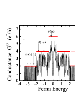
As an example of quantum transport properties of our model Hamiltonian Eq. (3), Fig. 2 plots the total conductance of the finite width ring as a function of . The strength of the Rashba SO coupling is fixed at , where we introduce the dimensionless Rashba SO parameter with as the radius of the outermost ring. Furthermore, we assume that the system is free from impurities , and that coupling energies between the conductor and the leads are set to be the same as the hopping energy in the leads . The calculated conductance exhibits rapid oscillations with peaks occurring at eigenenergies of the corresponding closed 2D ring. While the conductance oscillates regularly in the single-channel regime, the oscillation pattern in the multichannel regime is rather intricate since the occupation of the higher radial modes gives rise to new conductance peaks in addition to the ones originating from the lowest radial mode.

III Spin-interference effects in single-channel quantum transport through AC rings
In this section we study how can be modulated as we change the strength of the Rashba SO coupling in both strictly 1D rings and single open channel of 2D rings. The transport through phase-coherent 1D rings, described by the correct Hamiltonian meijer Eq. (2) has been analyzed recently, diego in terms of the expressions for of the ring of radius that does not involve dependence on the Fermi energy
| (26) |
Here has the meaning of the spin precession angle over the circumference of 1D ring. However, such simplified expression neglects the back scattering at the interface between the ring and the leads. A more involved treatment that takes into account such effects has been undertaken in Ref. molnar, . Nevertheless, no analytical expression has been obtained for single-channel transport in 2D rings.
We confirm molnar in Figure 3 that the exact pattern of zero-temperature versus Rashba SO coupling strength depends on the Fermi energy of transported electrons. This is due to the back scattering effects at the interfaces between the ring and the leads, which can strongly affect the transport. Nevertheless, all of the calculated conductance curves have dips at specific values of that are spaced quasi-periodically diego in a way which does not depend on . Thus, the zeros of the conductance in Fig. 3 agree well with those predicted by Eq. (26), i.e., their position is insensitive to the lead-ring back scattering effects.
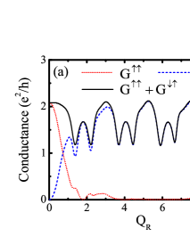
In order to understand the origin of the conductance modulation in more detail, we plot the spin-resolved conductances for a given Fermi energy in Fig. 4. Here we consider the conductances corresponding to the injection of current which is fully spin- polarized along the -axis. As increases, decays while the spin-flipped conductance increases. That is, at the interface between the ring and the left lead, the injected spin- (along the -axis) finds itself to be parallel or antiparallel to the effective -dependent Rashba magnetic field that appears in the frame of electrons circulating along the ring (see Fig. 1). In the presence of large enough Rashba SO coupling, the injected spin- polarized current will change its spin polarization by following the direction of adiabatically. The corresponding outgoing current will appear in the right lead as spin- polarized current. The summation of those two components is equal to half of the total conductance plotted in Fig. 3.
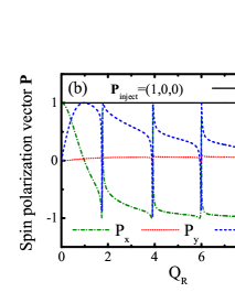
The spin polarization vector of the transmitted current in Fig. 4 further clarifies this insight. We see that with increasing SO coupling, in the right lead rotates from at to the asymptotic value at large . The functions and are, however, not monotonous since there are abrupt changes of their directions at specific values of for which . Thus, one can also exploit the AC ring in schemes where the spin-polarization of fully polarized injected current is switched to the opposite direction via external electric field applied through a gate electrode covering the ring. switch For quantum-interference effects, it is important to note that the purity of transported spins remains one. Therefore, preservation of full quantum coherence ensures complete visibility of the destructive spin-interference effects that give rise to .
Furthermore, our framework makes it possible to study single-channel transport through 2D ring, as shown in Figure 5 which plots the -dependence of for the finite-width rings and at different Fermi energies selected by the vertical arrows (a)–(c) in Fig. 2. At these values , only one conducting channel is available for quantum transport. We emphasize that the single-channel transport in finite width conductors is not equivalent to the transport in strictly 1D rings ring ; diego ; molnar since the presence of unoccupied modes (evanescent modes) can influence the transport flowing through the open channel in a way which depends on the confinement potential and the geometry of the conductor. decoherence ; hausler While Fig. 5 shows that the calculated conductance still exhibits zeros at approximately the same values of as in the strictly 1D case, diego we emphasize that such zeros can be washed out for transport occurring at specific Fermi energies (see also Fig. 9). Also, the conductance oscillation patterns are rather irregular compared with the strictly 1D case, especially in the large regime.
IV Visibility of spin-interference effects in multichannel quantum transport through AC rings
IV.1 Injecting current through spin-polarized conducting channels
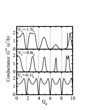
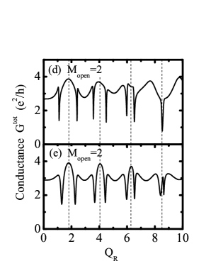
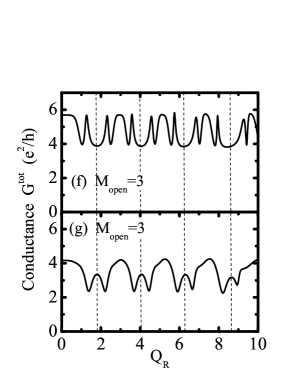
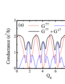
In Fig. 6 we show the conductance of the finite width ring for various Fermi energies which are indicated by vertical arrows (d)–(g) in Fig. 2. More than one transverse propagating mode in the leads exist at these Fermi energies. Therefore, one can view the injected current as being comprised of electrons prepared in all of different quantum state (). For non-magnetic leads, both and electrons are injected into the ring. The number of the conducting channels is denoted in the Figure. Although conductance continues to display oscillating behavior as a function of even in the multichannel transport, its pattern is rather different from the single channel case due to lack of points. Furthermore, the conductance oscillation pattern is significantly more sensitive to the Fermi energy than in the single channel case.
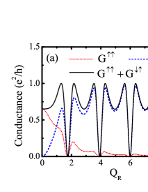
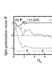
The spin-resolved conductances in Fig. 7 for a given Fermi energy (at which ) provide a more detailed information about such ”incomplete” conductance modulation. Here we consider the conductances corresponding to the injection of spin- polarized current. Similarly to the case of strictly 1D ring, the spin-conserved conductance decays while the spin-flipped conductance increases as increasing . Their sum is just half of the total conductance plotted in Fig. 6. Despite the fact that multichannel AC rings are not able to modulate (i.e., at any ) unpolarized current to the extent found in 1D rings (where at specific values of ), the properties of current spin-polarization vector in Fig. 7 suggest that they can serve as, even better than 1D rings, switch spin-switch devices. That is, at large such device flips the spin- of an incoming electron in the left lead into spin- of the outgoing electron in the right lead.
The most prominent distinction between the single and the multichannel cases is that the modulus of the spin polarization can drop below one—the spin state injected into the multichannel ring loses its purity for . This is very contrastive to the single channel transport case where the is exactly satisfied at any . Such a reduction of is attributed to the fact that finite Rashba SO coupling can induce entanglement between the spin state of transported electron and its orbital state, leaving a spin in a mixed quantum state .
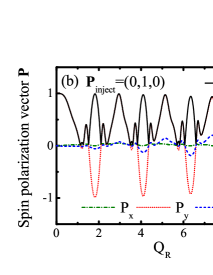
The spin-resolved conductances and spin polarization vector behave rather differently depending on the polarization of the injected spin, as demonstrated by comparing Fig. 7 and Fig. 8, where we change the direction of polarization of injected spin- current to lie along the -axis. In this case, both the spin conserved conductance and the spin flipped conductance oscillate and contribute to the total conductance on any interval of . This is because the polarization of injected current in this case is orthogonal to the direction of field at the interface between the left lead and the ring (see Fig. 1). Thus, the injected spin will be transported through the ring as a superposition of and spin states along the radial direction which causes the oscillations of and . When the -polarized current is injected, and characterizing the spin current are close to zero, while exhibits quasi-periodic oscillation (note that, according to Eq. (21) oscillations in are in one-to-one correspondence with oscillations of and ). Since , the purity of the transported spin state is approximately given by .
IV.2 Injecting current through eigenchannels
In strictly 1D rings (or transport through a single open channel of a 2D ring) the conductance goes to zero (or , see Fig. 9 in the regime ) at specific values of the Rashba SO coupling due to destructive interference effects in coherent superpositions , as discussed in Sec. III. When current is injected also through higher transverse modes, the analysis of the ring transport properties becomes much more involved. Nevertheless, one can envisage unfolding of three plausible scenarios:
-
1.
The difference in AC phases acquired by spin states is the upper and lower branches of the ring is independent of the wave vector of transverse modes, so that electron remains in a separable quantum state (i.e., the transmission matrix can be decoupled into a tensor product of spin-dependent part and a spatial scattering part entin ); in this case the conditions for destructive interference remain the same as in single-channel quantum transport, ring
-
2.
The transmitted spins through different channels, each of which has its own orbital phase, pick up different AC phases so that conditions for a destructive interference cannot be satisfied simultaneously in all channels,
-
3.
The transmitted spins lose their coherence due to coupling to environment, i.e., the off-diagonal elements of the spin density matrix are decaying in the course of transport; decoherence if they do not diminish all the way to zero, the transported spin will end up in a partially coherent quantum state. gefen ; partial_fano
In both the first and the second scenario, the spin is described by a pure quantum state in the course of transport. Although the second and the third scenario lead to the same observable consequences—the ring conductance never reaches zero since visibility gefen of the spin-interference effects is reduced below one—they are fundamentally different. In the second scenario, spin states remain fully coherent, while in the third one transmitted spins are partially coherent due to coupling to the environment. Even when all other (usually many-body partial_fano ) decoherence mechanisms are suppressed, single spin of an electron can still be entangled to the environment composed of its orbital channels. This mechanism becomes operable in the clean ring when spin-independent charge scattering off boundaries and interfaces occurs in the presence of SO coupling. decoherence The partially coherent states, as an outcome of entanglement of spin of transmitted electron with the spin in a quantum dot, were also found in recent experiments on Aharonov-Bohm ring interferometers where quantum dot is embedded in one ring arms. partial_fano
Here we explore possibility of the same partially coherent outgoing spin state to appear in the AC ring, where physical mechanism of entanglement is different and single-particle in nature. decoherence This makes investigation of ring transport properties in terms of
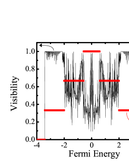
the AC phases acquired by circulating spins rather difficult since one has to extract geometric phase of an open spin quantum system described by the density matrix rather than by a pure state. vedral It is insightful to define the visibility of quantum interference effects in the AC ring
| (27) |
Here and are the maximum and the minimum values of the total conductance found in the first period of the conductance oscillations vs. , for a given Fermi energy and corresponding number of open channels . The visibility in 2D rings allowing for a maximum of three open channels is plotted in Fig. 9, which shows that in the single-channel transport regime, i.e., the unpolarized charge transport can be fully modulated by changing the strength of the Rashba SO interaction (except at particular Fermi energies). However, as soon as the second channel starts contributing to the transport, decreases below one.


To investigate which of the above scenarios is realized in the transport through multichannel rings, it is advantageous to invoke as much as possible transparent picture of spin-interference effects in 1D rings. ring ; diego ; molnar Thus, to be able to consider the transport through multichannel ring as if taking place through a system of independent single-channel rings, we switch to the representation of eigenchannels. In general, the basis of eigenchannels, in which is a diagonal matrix, offers a simple intuitive picture of the transport in a mesoscopic conductor that can be viewed as a parallel circuit of independent channels characterized by channel-dependent transmission probabilities . The computation of as eigenvalues of in the case of conventional unpolarized charge transport allows one to obtain a plethora of transport quantities beyond just the conductance through simple expressions. carlo_rmt However, the rotation to the diagonal matrix is inapplicable decoherence in spintronics where usually the spin density matrix of injected electrons is non-trivial in the incoming channels of the leads. Nevertheless, when both spin- and spin- are injected into the ring in equal proportion, the basis of eigenchannels allows us to ”deconstruct” 2D ring into single-channel rings. Moreover, in systems with SO interaction, which are time-reversal invariant in the absence of external magnetic field, due to the Kramers degeneracy all transmission eigenvalues are double degenerate. carlo_rmt In the case of single-channel rings of Sec. III this correspond to both spin- and spin- electrons giving identical contribution to . The observable transport properties of a multichannel ring cannot differentiate between injection of unpolarized current through spin-polarized channels defined by the leads as a boundary condition (which were utilized in Sec. IV.1) or through the eigenchannels.
The spin properties of eigenstates of can be described by assigning the density matrix to each eigenchannel
| (28) |
and then taking the partial trace over the orbital degrees of freedom to get the reduced density matrix for the spin subsystem of an eigenchannel
| (29) |
This allows us to extract the purity of the spin subsystem of an eigenchannel from .
Figure 10 shows the total conductance, the eigenchannel transmissions, and the spin purity of an eigenchannel of the two-channel ring conductor at two different values of the Fermi energy ensuring that both conducting channels in the leads are open for transport. Here we plot only the spin purity corresponding to the first eigenchannel (spin purity of other eigenchannels display similar behavior). Since the eigenchannel transmissivities are twofold degenerate, one can observer only two different values of at each in Fig. 10. When , the total conductance shows incomplete modulation since the conductance never reaches zero value. It is possible to recognize in Fig. 10 that the eigenchannel transmissions form two distinctive curves as a function of . Furthermore, each of them exhibits full-modulation characterized by at particular values of . However, these two oscillating patterns are shifted with respect to each other, thereby preventing total conductance from reaching zero value at any strength of the SO interaction. This can be explained as a realization of the second scenario introduced above. On the other hand, at the total conductance shows almost complete modulation because: (i) the individual eigenchannel transmissions are akin to the ones found in single-channel rings; and (ii) they almost completely overlap with each other. This case, albeit found rarely in multichannel AC rings, represents quite a good example of the first scenario mechanism. Interestingly enough, drops below one (meaning that an electron is “injected” into the conductor in an entangled state of spin and orbital channels) at those values of where one would expect destructive interference effects of pure spin states in single-channel rings or system of such independent rings.
Figure 11 plots the same eigenchannel physical quantities for the transport through a three-channel ring , where is set to allow all three channels to be opened. The total conductance in this case also displays incomplete modulation . However, in this case only one curve can isolated that oscillates between 0 and 1, while the other two never reach zero values. Moreover, these three patterns of are shifted with respect to each other. This observation within the picture of three independent single channels explains why the oscillations of the total conductance end up having a rather small amplitude - .
V Conclusion
In conclusion, we have investigated how the conductance of unpolarized electron transport through two-dimensional rings changes as we increase the strength of the Rashba SO coupling. Moreover, we connect the properties of the charge transport to the orientation of spin of injected electrons as well as its coherence properties. In order to take into account the effect the finite width of the ring and the leads systematically, we model the ring using concentric tight-binding lattice Hamiltonian as the starting point for the calculation of charge and spin transport properties based using the Landauer transmission matrix for a two-probe device.
Our analysis suggests that conductance oscillations, induced by changing the Rashba SO coupling, will persist to some extent even in the multichannel transport through mesoscopic ring-shaped conductors. However, the oscillation patterns are rather different from the single-channel case, or from the anticipated oscillations in multichannel rings where spin-interference effects would be equivalent in all channels and simply add up. The conductance of single-channel transport through the ring displays full modulation, where appears quasi-periodically as a function of the Rashba SO coupling. This effect is explained in simple terms ring ; diego ; molnar as a result of destructive spin-interference effects between opposite spin states circulating in the clockwise and counterclockwise direction around the ring, where they acquire Aharonov-Casher phase in the presence of the Rashba electric field. On the other hand, quantum transport in most of the cases occurring in multichannel rings does not lead to zero conductance at any Rashba coupling. Using the picture of quantum transport through independent eigenchannels, we identify different scenarios washing out feature of the single-channel transport, which involve either pure or mixed transported spin states. As the number of conducting channels increases, it becomes more likely to generate partially coherent transported spin (which is described by the density matrix rather than the pure state vector) due to entanglement of electron spin to its orbital degrees of freedom. decoherence
Acknowledgements.
We thank F. E. Meijer, J. Nitta, and M. Shayegan, and D. Pappas for sharing with us important experimental insights.References
- (1) I. Žutić, J. Fabian, and S. Das Sarma, Rev. Mod. Phys. 76, 323 (2004).
- (2) E.I. Rashba, Physica E 20, 189 (2004).
- (3) D.D. Awschalom and J.M. Kikkawa, Phys. Today 52, 33 (1999).
- (4) S. Datta and B. Das, Appl. Phys. Lett. 56, 665 (1990).
- (5) J. Nitta, T. Akazaki, H. Takayanagi, and T. Enoki, Phys. Rev. Lett. 78, 1335 (1997).
- (6) Y. Ohno, D.K. Young, B. Beschoten, F. Matsukura, H. Ohno, D.D. Awschalom, Nature 402, 790 (1999); R. Fiederling, M. Keim, G. Reuscher, W. Ossau, G. Schmidt, A. Waag, and L. W. Molenkamp, Nature 402, 790 (1999).
- (7) F.G. Monzon, M. Johnson, and M.L. Roukes, Appl. Phys. Lett. 71, 3087 (1997).
- (8) Y. Imry, Introduction to mesoscopic physics (Oxford University Press, Oxford, 2002).
- (9) C.W.J. Beenakker, Rev. Mod. Phys. 69, 731 (1997).
- (10) S. Washburn and R.A. Webb, Rep. Prog. Phys. 55, 1311 (1992).
- (11) A. Bohm, A. Mostafazadeh, H. Koizumi, Q. Niu, and J. Zanziger, The geometric phase in quantum systems (Springer-Verlag, Berlin, 2003).
- (12) Y. Meir, Y. Gefen, O. Entin-Wohlman, Phys. Rev. Lett. 63, 798 (1989).
- (13) H. Mathur and A.D. Stone, Phys. Rev. Lett. 68, 2964 (1992).
- (14) A.G. Aronov and Y.B. Lyanda-Geller, Phys. Rev. Lett. 70, 343 (1993).
- (15) T.-Z. Qian and Z.-B. Su, Phys. Rev. Lett. 72, 2311 (1994).
- (16) J. Nitta, F.E. Meijer, and H. Takayanagi, Appl. Phys. Lett. 75, 695 (1999).
- (17) D. Frustaglia and K. Richter, cond-mat/0309228.
- (18) B. Molnár, and F.M. Peeters, P. Vasilopoulos, Phys. Rev. B 69, 155335 (2004).
- (19) B.K. Nikolić and S. Souma, cond-mat/0402662.
- (20) W. Häusler, Physica E 18, 337 (2003).
- (21) J.B. Yau, E.P. De Poortere, and M. Shayegan, Phys. Rev. Lett. 88, 146801 (2002).
- (22) M.J. Yang, C.H. Yang, K.A. Cheng, and Y.B. Lyanda-Geller, cond-mat/0208260.
- (23) F.E. Meijer, A.F. Morpurgo, and T.M. Klapwijk, Phys. Rev. B 66, 033107 (2002).
- (24) J.L. D’Amato, H.M. Pastawski, and J.F. Weisz, Phys. Rev. B 39, 3554 (1989).
- (25) A. Aldea, P. Gartner, and I. Corcotoi, Phys. Rev. B 45, 14122 (1992).
- (26) K.N. Pichugin and A.F. Sadreev, Phys. Rev. B 56, 9662 (1997).
- (27) W. Zurek, Rev. Mod. Phys. 75, 715 (2003).
- (28) S.-Q. Shen, Z.-J. Li, and Z. Ma, Appl. Phys. Lett. 84, 996 (2004).
- (29) Y. Gefen, in Strongly Correlated Fermions and Bosons in Low-Dimensional Disordered Systems, edited by I.V. Lerner, B.L. Altshuler, V.I. Fal’ko, and T. Giamarchi (Kluwer, Dodrecht, 2002) (cond-mat/0207440).
- (30) H. Aikawa, K. Kobayashi, A. Sano, S. Katsumoto, and Y. Iye, Phys. Rev. Lett. 92, 176802 (2004).
- (31) A. Carollo, I. Fuentes-Guiridi, M. França Santos, and V. Vedral, Phys. Rev. Lett. 90, 160402 (2003); R.S. Whitney and Y. Gefen, Phys. Rev. Lett. 90, 190402 (2003).