Polyelectrolyte-surfactant complex:
phases of self-assembled structures
Abstract
We study the structure of complexes formed between ionic surfactants (SF) and a single oppositely charged polyelectrolyte (PE) chain. For our computer simulation we use the “primitive” electrolyte model: while the polyelectrolyte is modeled by a tethered chain of charged hard sphere beads, the surfactant molecules consist of a single charged head bead tethered to a tail of tethered hard spheres. A hydrophobic attraction between the tail beads is introduced by assuming a Lennard-Jones potential outside the hard-sphere diameter. As a function of the strengths of both the electrostatic and the hydrophobic interactions, we find the following scenario: switching on and increasing the electrostatic forces first leads to a stretching of the PE and then by condensation of SF to the formation of a complex. For vanishing hydrophobic forces this complex has the architecture of a molecular bottle-brush cylindrically centered around the stretched PE molecule. Upon increasing the hydrophobic attraction between the SF tails, a transition occurs inverting this structure to a spherical micelle with a neutral core of SF tails and a charged corona of SF heads with the PE molecule wrapped around. At intermediate hydrophobicity there is a competition between the two structures indicated by a non-monotonic dependence of the shape as function of the Coulomb strength, favoring the cylindrical shape for weak and the spherical micellar complex for strong interaction.
pacs:
82.70.-y,61.20.Ja,82.35.Rs,83.80.QrI Introduction
Polyelectrolyte-surfactant mixtures have proven to provide the basis for new materials with extraordinary properties that make them interesting for a wide range of applications Kwak (1998); Antonietti et al. (1997). In particular the Coulomb attraction between polyelectrolyte chains and oppositely charged ionic surfactant molecules in solution leads to aggregation and complex formation. The resulting complex differs in its conformational, structural and dynamical features from that of solution containing only one of its constituents, the pure polyelectrolyte or the pure surfactant (for reviews see Hansson and Lindman (1996); Kwak (1998)). Much experimental work has been done on these systems and a rich variety of different complex structures was revealed as a function of chemical nature of the polyelectrolyte, surfactant and solvent molecules Sokolov et al. (1998); Kosmella et al. (1998); Claesson et al. (1998); Tsianou and Alexandridis (1999); Thünemann et al. (2000); Dias et al. (2000); Babak et al. (2000); Liao and Higgins (2001); Guan et al. (2001); Taylor and Thomas (2002); Hansson et al. (2002); Guillot et al. (2003). A theory that could give a systematic microscopic characterization and prediction of the different complexes on the other hand does not exist so far.
Already for complexes formed by a single polyelectrolyte chain with ionic and hydrophobic surfactants at low concentration a theoretic treatment that takes the long-ranged Coulomb interaction and the hydrophobic interactions fully into account is still to be developed. The case without hydrophobicity has recently been simulated by the present authors von Ferber and Löwen (2003). For these single polyelectrolyte complexes one expects structures either of bottle-brush shape for low hydrophobicity or, for strong hydrophobicity, possibly spherical micelles that aggregate together with the polyelectrolyte chain Antonietti et al. (1997); Wallin and Linse (1998). Theories so far in general make assumptions about the symmetry or the structure of the complex implying a complete adsorption of surfactant onto the polyelectrolytes for rigid Shirahama et al. (1981); Shirahama and Tashiro (1984) and flexible chains, see e.g. Sear (1998) and cannot predict the complex structure or its symmetry Wallin and Linse (1998) as far as it enters the theory as an input. For the special case of a system of rigid polyelectrolytes that form complexes via thermodynamic counterion condensation including the effect of added surfactant a theory has recently been developed by Kuhn, Levin and coworkers Kuhn et al. (1998, 2000); Silva et al. (2001). The collapse and partial collapse of semiflexible and flexible polymers in solutions with surfactants has been treated by a meanfield association theory by Diamant and Andelman Diamant and Andelman (2000a, b). However, this theory does not include explicitly the long range of the Coulomb interactions. A self consistent field theory with a spherically symmetric setup Wallin and Linse (1998) on the other hand predicts the formation of spherically symmetric micelles with a neutral hydrophobic core and a surface layer where the charged surfactant heads and the oppositely charged polyelectrolyte are located. Based on this observation it has been proposed to simplify the model by replacing the ionic surfactant by large spherical counterions not treating the surfactant tails explicitly Wallin and Linse (1996). For a system of a polyelectrolyte in the presence of small counterions computer simulations Stevens and Kremer (1995); Winkler et al. (1998); Micka et al. (1999) and theories Brilliantov et al. (1998); Kuhn (2002) find a swelling and stretching of the polyelectrolyte and a subsequent collapse when increasing the Coulomb interaction. In this scenario a non-monotonic dependence of the of the polyelectrolyte
conformation as a function of the Coulomb strength occurs: for weak Coulomb strength the PE stretches while in the strong Coulomb regime counterion condensation and a collapse to a coil conformation occurs. For large counterions representing micelles the polyelectrolyte may be wrapped around the charged sphere exhibiting different conformations depending on the chain flexibility Wallin and Linse (1996); Gurovitch and Sens (1999); Mateescu et al. (1999); Netz and Joanny (1999); Park et al. (1999); Kunze and Netz (2000); Nguyen and Shklovskii (2000); Welch and Muthukumar (2000); Schiessel et al. (2001); Jonsson and Linse (2001a, b); Akinchina and Linse (2002); Chodanowski and Stoll (2001a, b); Brynda et al. (2002); Keren et al. (2002).
The bottle brush structure that is expected for the condensation of charged ionic surfactants onto a polyelectrolyte chain may be compared with corresponding neutral molecular bottle brushes in case the polarization effects in the complex are neglected. Such neutral bottle brush or comb polymers are built either by end linking the side chains to the backbone chain or by attaching them via strong hydrogen bonds ten Brinke and Ikkala (1997); Ruokolainen et al. (1996). Such configurations may be expected to become more rigid for higher densities of the side chains. A quantitative description, however, is still under debate since different simple scaling arguments Birshtein et al. (1987); Fredrickson (1993); Rouault and Borisov (1996) appear to predict different quantitative behavior for the sizes of the main and side chains depending on the model used and the limit that is considered Khalatur et al. (2000).
In the present paper we explore by computer simulation the phases of complex formation of a single polyelectrolyte chain with ionic surfactants in the phase space parameterized by the strengths of the Coulombic interactions and the hydrophobic attraction between the surfactant tails. As in our previous study von Ferber and Löwen (2003) our simulation relies on the so-called “primitive” model Hansen and Löwen (2000) that treats the microscopic charges of the polyelectrolyte and the surfactant heads explicitly. This is in contrast to simulations on polymer-surfactant complexation which neglect the long-range nature of the Coulomb interactions Groot (2000). The “primitive” model has recently also been applied to simulate the complexation of polyelectrolyte chains with charged spheres representing spherical micelles Rescic and Linse (2000) and has proven to be reliable in different contexts of polyelectrolyte conformations Stevens and Kremer (1995); Winkler et al. (1998); Micka et al. (1999); Wallin and Linse (1997); Winkler et al. (2002); Jusufi et al. (2002); Messina et al. (2002a).
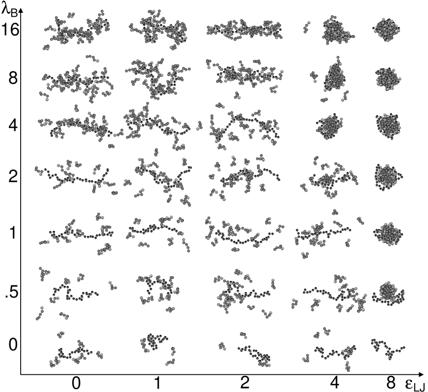
To treat surfactants with neutral or hydrophobic tails we model the surfactant by a tethered hard sphere chain with a charged head and a Lennard-Jones like effective attraction between the hydrophobic tail monomers allowing for the formation of micelles. As a result, we observe different phases of complexation depending on the strengths of the two interactions involved: the Coulomb and the hydrophobic interaction. An overview of these phases is given in Fig. 1 in terms of simulation snapshots. For vanishing hydrophobicity (leftmost column of Fig. 1) the mean square end-end distance of the polyelectrolyte is non-monotonic as function of the Coulomb interaction. However, in contrast to the standard situation where a collapse of the polyelectrolyte due to counterion condensation occurs Stevens and Kremer (1995); Winkler et al. (1998); Micka et al. (1999), such a collapse is blocked by the steric interaction of the surfactant tails. As we have shown in Ref. von Ferber and Löwen (2003), for even longer surfactant tails the collapse is more sufficiently blocked, while the addition of salt weakens the complex as it replaces the surfactant in the complex. Increasing the hydrophobicity for vanishing Coulomb interaction on the other hand (bottom row of Fig.1) leads to the aggregation of micellar clusters of surfactant molecules that are independent from the polyelectrolyte chain. Introducing a finite Coulomb strength in this latter situation favors the condensation of the surfactant at the polyelectrolyte. Thirdly we may start with a bottle brush conformation of the complex at high Coulomb but vanishing hydrophobic interactions (top left of Fig.1). Gradually increasing the hydrophobicity (along the top row of Fig.1) the tails start to aggregate and and a transition occurs from the cylindrical structure with the tails on the outside to an inverted spherical structure with a core that is constituted by the surfactant tails. In our present resolution this transition appears to be sharp.
The paper is organized as follows: in section II, we describe our model in detail and we present details of the simulation procedure in section III. Results are given in section IV and we conclude in section V.
II The Model
In our simulation we model all molecules as chains of tethered hard spheres (beads) that represent Kuhnian segments of the molecule. Microions are modeled by hard sphere beads. Charges on these molecules and ions are represented by placing a point charges at the center of any charged bead. In this primitive model the solvent is not treated explicitly and only enters via its dielectric constant neglecting the discreteness of the solvent molecules. The microscopic interactions between the particles are given by the hard sphere excluded volume, the long-ranged Coulomb forces, and a short range hydrophobic interaction. We reduce the model parameter space by fixing the hard sphere diameter of all beads in the system to the same value . Furthermore, all charged beads have the same charge with denoting the elementary charge. While this “minimal” model explicitly handles the counter ions and may be used to describe strongly charged, flexible polyelectrolytes Stevens and Kremer (1995), analytical calculations usually neglect the individual character of the counter ions Odijk (1979); Fixman and Skolnik (1978); deGennes et al. (1976); Barrat and Joanny (1993).
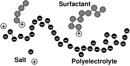
As mentioned above, all molecules are modeled by chains of freely jointed, tethered hard sphere beads. Subsequent beads in the same chain are tethered. The extension of all bonds is limited by the tether to a fixed value . For vanishing Coulomb and hydrophobic interactions the model is purely entropic (i.e. temperature-independent). Our specific parameters are such that the polyelectrolyte is represented by a chain of charged beads each with charge . The surfactant molecules on the other hand are chains of tethered beads with one charged head bead of charge and neutral tail beads that may interact due to hydrophobicity. The full model may also contain salt which has been treated in Ref.von Ferber and Löwen (2003). The salt ions are then represented by single charged beads. The constituents of the model of polyelectrolytes, surfactant molecules and microions is schematically shown in Figure 2.
In our model, the effective interaction due to hydrophobicity of the surfactant tails is given by a Lennard-Jones like potential between the tail monomers. This approach has also been used in the context of copolymer micellization Connolly et al. (2003); Timoshenko and Kuznetsov (2000). The explicit interaction between any two beads of the model at a distance between their centers is given by a potential . To denote chain connectivity we use an adjacency matrix . For beads that are tethered otherwise . With denoting the charge and the hydrophobicity number of bead , the potential is given by
| (1) |
Here, the dimensionless Coulomb strength is the Bjerrum length measured in bead diameters . The Bjerrum length sets the length scale where the Coulomb pair interaction is comparable to the thermal energy . The dimensionless hydrophobicity parameter controls the depth of the Lennard-Jones potential. Furthermore, the hard core and tether interactions are represented by the one dimensional hard wall potential
| (2) |
We note that in our notation the product is defined to be zero if is zero.
The key parameters of our model are: the number of charged monomers of the polyelectrolyte chain, the number of neutral beads of the surfactant tails, the parameters and which measure the strengths of the Coulomb and hydrophobic interactions and finally the relative salt concentration . In the following we shall explore the parameter space in particular in the two variables and while keeping fixed the particle hard-core diameters, the microion charges , the monomer number and the maximal tether length and in general also the salt concentration and the surfactant length . In our previous work von Ferber and Löwen (2003) we also investigated the influence of surfactant tail variation as well as of finite salt concentration. A brief discussion of the corresponding results is also included in the following.
III Simulation Technique
We simulate by standard Monte Carlo (MC) methods a system of a single polyelectrolyte chain of charged beads at finite concentration with polyelectrolyte charge density which is kept fixed throughout all simulations. The finite concentration is taken into account by periodic boundary conditions of our finite cubic simulation box of length and replicated images of the charges. Summations over the interactions with the periodic images are calculated by the Lekner sum method Lekner (1991). The Metropolis rates of the MC moves are determined by the interactions given by Eqn. (1).
The relaxation of the system, especially in the fully assembled bottle brush configurations is very slow. This is also known from simulations of conventional bottle brush molecules Khalatur et al. (2000). To ensure sufficient relaxation we performed attempted MC moves per particle at each state point. The acceptance ratio is roughly in situations with an open structure. In the micellar cases however, caging occurs inside the densely packed core reducing the acceptance rate down to .
In all simulations the global charge of our system vanishes. We performed simulations for a system of a single polyelectrolyte chain together with oppositely charged surfactant molecules. The case of no tail beads at all serves as a natural reference for pure counter ions. Such a situation was already studied in Ref. Stevens and Kremer (1995) and implemented in the frames of the present setup in Ref. von Ferber and Löwen (2003) for different Bjerrum lengths. Note, however, that chain connectivity was modeled differently in Ref. Stevens and Kremer (1995) via a finite extension potential.
IV Results
IV.1 Zero hydrophobicity of the surfactant
In the case of vanishing hydrophobic interactions the surfactant tails interact only due their steric repulsion. This special case was treated by the present authors in von Ferber and Löwen (2003) in detail, so we only recall some of the basic results. We first discuss the case of no added salt. As a reference situation serves the a surfactant without tail, i.e. . The averaged square end-to-end distance of the polyelectrolyte chain is defined via
| (3) |
where denotes a statistical average and and are the actual positions of the two end-monomers of the polyelectrolyte.

is plotted as a function of Coulomb strength in Fig. 3. Here, the collapse scenario found in other simulations Stevens and Kremer (1995); Winkler et al. (1998); Micka et al. (1999) and analytical treatments Schiessel and Pincus (1998) is confirmed. This scenario for simple counterions is the following: At zero Bjerrum length the interaction is purely excluded volume and the chain attains a polymer coil configuration. Increasing the chain stretches due to the repulsion of its charged beads. For low the counterion screening is weak and stretching continues until is of the order of the counterion diameter, i.e. . For larger the condensation of counterions induces a shrinking of the PE extension which for high may even be become smaller than the neutral coil; an effect not yet seen in the range for that we simulated.
Substituting in the former system the counterions by charged surfactants with neutral tails the behavior as function of the Coulomb strength changes in the following way: The PE chain stretches for increasing with the maximal extension attained for higher values of corresponding the the larger effective diameter of the charged surfactant acting as a counterion. When counterion condensation occurs at higher the surfactant and the PE chain form a complex in which the surfactants aggregate with their heads near the PE chain and their tails pointing away from the PE chain in a manner resembling the structure of a molecular bottle brush. The subsequent collapse of the PE chain that is observed in the previous scenario now is effectively blocked due to the excluded volume interaction of the surfactant tails. The internal structure of this complex is discussed below. For the special case of vanishing hydrophobicity the influence of added salt on the end-to-end distance was investigated in Ref.von Ferber and Löwen (2003).

Adding additional salt pairs to our system we define the relative concentration as where is the number of charges on the polyelectrolyte. The results are shown in Fig. 4. The surfactant molecules in the complex are replaced in favor of salt ions. This is driven by entropy of mixing and corresponds to a chemical equilibrium. The replacement is therefore increasing with increasing salt concentration. This destroys the structure of the complex as seen from the reduction in the end-to-end distance of the polyelectrolyte.
In all our simulations we observe that the contour length of the polyelectrolyte given by the sum of the bond lengths is very stable under all changes of the parameters. Varying the Bjerrum length in the range we find a corresponding increase from to , a change that is within the statistical uncertainty. For this reason also the persistence length does not give additional information. For a worm-like chain namely it is related to the end-end distance and the contour length by Doi and Edwards (1986)
| (4) |
a relation also confirmed by simulations Stevens and Kremer (1995).
IV.2 Clusters and micelles
The results described in this and the following sections section all refer to a system with a single polyelectrolyte chain of 32 charged beads and 32 oppositely charged 5-bead surfactant molecules with one charged head bead and four neutral possibly hydrophobic tail beads. For finite values of the Coulombic and hydrophobic interactions we observe in general one or more aggregates or clusters of molecules. To analyze these structures in detail we define the clusters by assuming that any two beads belong to the same cluster if their distance is less than . Among these clusters we identify the complex as the one that contains the polyelectrolyte chain.

We monitor the number of clusters and the sizes of the complex and of the largest aggregates that are detached from the polyelectrolyte. These latter aggregates we identify with isolated micelles. The number of identified clusters is shown in Fig. 5 as a function of the Coulomb interaction parameter for different values of the hydrophobicity strength : For vanishing interactions clustering occurs only by chance and almost each cluster observed represents one of the 33 single molecules in the system. For increasing interactions the molecules condense to a few larger clusters with only one or two remaining in the strong interaction case. When the Coulomb interaction vanishes, i.e. , the polyelectrolyte will always be detached from the micelles and thus a minimal number of two clusters remain even for strong hydrophobic attraction. For any finite Coulomb interaction and high hydrophobicity on the other hand all molecules condense to a single complex in the present setup.


The sizes of the complex and of the largest detached micelle are shown in Fig. 6 where we plot the masses of these aggregates as function of the Coulomb parameter for different values of the hydrophobicity . It is clearly seen from these plots that a large detached micelle appears only for small Coulombic strength and high hydrophobic attraction . For these high the largest detached micelle shrinks rapidly with increasing while at the same time the mass of the complex grows such that the surfactant is nearly quantitatively condensed in the complex for . For smaller hydrophobicity on the other hand no larger detached micelles appear at all while the mass of the complex grows only moderately for increasing Coulombic strength . Thus, while for high hydrophobicity the size of the largest detached micelle is inversely related to the size of the complex, the absence of large micelles for smaller hydrophobicity may be explained with their instability due to the Coulombic repulsion between the charged surfactants in combination with entropy. As shown in the appendix the total binding energy of the surfactant tails in the micelle grows with proportionally to its mass with a surface correction proportional to . The electrostatic energy of the surfactant heads on the other hand is proportional to while the entropy term behaves like . The qualitative behavior of these three terms together with the approximate prefactors derived in the appendix may explain that for the finite number of available surfactants the formation of large detached micelles is unfavorable for and even for the mass of the largest detached micelle is significantly smaller than the total mass of available surfactant.
IV.3 Shapes of the complex
In the case of complex formation we characterize the shape of the complex in terms of its matrix of inertia
| (5) |
where the sum is over all beads that are part of the complex and is the position of bead with respect to the center of mass of the complex.


Diagonalizing results in the three eigenvalues with respective axes of the principal moments of inertia with the center of mass as the origin. Note that in these coordinates one has e.g.
| (6) |
such that the radius of gyration of the complex is given by . The relative values of the principal moments determine the global shape of the complex. The averaged ratios and are plotted as functions of the Coulomb strength for different hydrophobicities in Fig. 7. These serve as indicators for the transition of the complex from a cylindrical shape to an almost spherical one. The cylindrical shape is characterized by two large approximately equal inertia, i.e. and a third smaller moment such that . For an elongated cylindrical shape the -axis corresponding to the smallest moment is the symmetry axis. The spherical shapes in turn are characterized by three almost equal moments of inertia with . We observe the following - see Fig. 7: At only the PE chain is part of the ’complex’. The corresponding values we find for the neutral chain are and . These may be compared with and calculated from data found for self avoiding walks Zifferer (1998). Note that the relation is in accordance with the Schwartz inequality for averages. For weak hydrophobicity the shape of the complex remains cylindrical even for high Coulomb strength, while for strong hydrophobicity the transition from cylindrical to spherical shape occurs already for small Coulomb strengths . For the intermediate hydrophobicity though, we observe a competition between the formation of the cylindrical bottle brush and the spherical micellar complex. This fact is expressed by the non-monotonic behavior of the shape parameter as a function of . While for small the cylindrical shape wins and decreases with respect to the value of the neutral situation, a transition occurs between and where the shape parameter indicates a transition towards the spherical micellar complex, with increasing to and further towards for .

To verify the transition we analyze the internal structure of these intermediate states in more detail below. A similar division into strong, weak and intermediate hydrophobicity we find for the behavior of the square radius of gyration which is plotted as function of in Fig. 8. For small hydrophobicity the behavior of parallels that of the square end-to-end distance as described above for the case . For high hydrophobicity the radius of gyration of the complex shrinks already for small to values corresponding to compact micellar complexes. Again, the intermediate case behaves special: For small Coulomb strengths the radius grows due to the stretching of the polyelectrolyte chain and only for higher it again shrinks below the polymer coil value but still remains well separated from the high hydrophobicity case.
IV.4 Internal structure of the complex
While the overall shape of the complex is characterized by the inertia matrix, its internal structure can be explored by either the internal monomer-monomer correlations or by the density distributions of the different complexes in a given reference frame. We have used both approaches to identify the key features of the self-assembled structures. To verify the idea of the molecular bottle brush like structures in the case of low hydrophobicity and high Coulomb strength , we have measured in particular the correlation between the polyelectrolyte monomers and the surfactant tail ends.

As shown in Fig . 9 using also data of ref. von Ferber and Löwen (2003) we indeed find that the surfactant tail end is found in this situation with highest probability at a distance from the polyelectrolyte chain that increases with the length of the tail in accordance with the bottle brush picture. To monitor, on the other hand, the internal reorganization along with the transition from the cylindrical bottle-brush to the spherical micellar aggregate, we chose as a reference frame a coordinate system defined by the directions of the principle moments of inertia of the complex with the origin at its center of mass. We define the -directions such that the corresponding moments are ordered by . As mentioned above, the -axis then is the symmetry axis for the averaged cylindrical structures.


In Figs. 10-12 we show exemplarily for typical conformations of the complex the density distributions measured in this coordinate system. For vanishing hydrophobicity and the corresponding distributions are shown in Figs. 10. The densities as function of the distance from the -axis as plotted in Fig. 10(a) show clearly that the polyelectrolyte monomers and the surfactant heads are localized near the symmetry ()-axis while the density of the surfactant-tail monomers surpasses that of the former two species at larger distances from the central axis. The distributions measured along the -axis on the other hand show the remarkable feature of maxima near the ends of the cylinder. Surprising as it may seem, this effect is even exhibited by the equilibrium coil of a neutral polymer chain and in particular in our simulation for vanishing interactions.


The spherical micellar complexes, on the other hand, which we observe for sufficiently large parameter values of and are characterized by density distributions along and perpendicular to the -axis that are nearly identical - see Fig. 11. Only the different differential volumes used for measurement lead to deviations. A more natural variable in the spherical case is of course the distance from the center of mass. The density as displayed in Fig. 11 parallels the corresponding results of Wallin and Linse obtained by a self consistent spherical lattice field approach Wallin and Linse (1998): The core of the micelle is formed by almost densely packed surfactant tails surrounded by surfactant heads that stick out of the surface and another layer that contains the polyelectrolyte chain.


A transitional structure found for the values and of the interactions near to the boundary between the two states is investigated in Fig. 12. Although the structure is much more loosely bound it rather parallels the micellar aggregate displaying however a less pronounced layering in the spherical density distribution, see Fig. 12. The comparison of Figs. 12 (a) and (b) however shows that the distributions display deviations from spherical symmetry. Nonetheless, the present data indicates that the transition between the two states of the complex is rather sharp.
V Conclusions
In extensive MC simulations we have investigated the behavior of a single polyelectrolyte chain that interacts with oppositely charged surfactant molecules taking into account both long range Coulomb and short range hydrophobic interactions. Exploring the parameter space in both of these interactions we have established a “phase diagram” for this system and several distinct regions (“phases”) with characteristic structural behavior of the system as sketched in Fig. 1: for weak interactions both constituents behave nearly independently and the PE chain has a possibly stretched coil conformation. For high Coulomb strength but weak hydrophobicity we observe the formation of a complex with a cylindrical bottle brush structure in which the PE chain is stretched along the cylinder axis. If both interactions are strong, an inverted spherical micellar complex structure emerges with the SF tails constituting the core of a spherical micelle and the SF heads and the PE chain confined to the surface of this sphere. For intermediate values of the hydrophobicity there is a competition between the two structurally different complexation modes resulting in a non-trivial behavior of the shape as function of the Coulomb strength. For high hydrophobicity, but low Coulomb interaction the surfactant forms micelles to which the PE chain is only loosely attached. As we have reported in Ref.von Ferber and Löwen (2003) complexation in this system is in general weakened by the addition of salt. Our results can in principle be verified in experiments by systematically varying the surfactant tail hydrophobicity and the surfactant/polyelectrolyte charge and/or the dielectric permittivity of the solvent.
A number of extensions of our present approach are possible and would be interesting to follow. Of particular interest would be a study of a multi PE-chain system. For small numbers of chains a corresponding simulation appears to be feasible using our present approach. One might expect to observe in such a case a competition between the cooperative assembly of a multichain complex and single chain complexation. At high densities in systems with many chains one expects the formation of layered structures with many different possible phasesThünemann (1997). However, high density and a large number of chains are out of reach of the present approach, due to the requirement of calculating the long range interaction between any pair of charged beads and the slowing down of the simulation by the caging effect at high densities. To simulate such systems either one has to release the hard sphere non-penetrability Groot (2003) or resort to lattice methods and simulate only with a screened shorter range Coulomb interaction.
Other situations that can lead to significant changes in the behavior might be found for a choice of different valency of the SF heads and the PE chains to study over-charging effects of the polyelectrolyte for high valency salt ions Messina et al. (2002b). Also, in general, introducing neutral beads to the PE chain and varying the distribution of charges along the chain may lead to significant effects. In addition, the chain stiffness has been shown to be an important parameter. For a single micelle modeled as a charged sphere, many recent studies have revealed different topologies of the defect depending on the chain stiffness Wallin and Linse (1996); Gurovitch and Sens (1999); Mateescu et al. (1999); Netz and Joanny (1999); Park et al. (1999); Kunze and Netz (2000); Nguyen and Shklovskii (2000); Welch and Muthukumar (2000); Schiessel et al. (2001); Jonsson and Linse (2001a, b); Akinchina and Linse (2002); Chodanowski and Stoll (2001a, b); Brynda et al. (2002); Keren et al. (2002).
VI Acknowledgments
We thank A. F. Thünemann, O. Farago, H. Diamant and R. Messina for helpful discussions. This work was supported by the Deutsche Forschungsgemeinschaft through grant No. LO 418/7.
VII Appendix
A crude argument for the stability of micelles built from our model surfactants can be derived from the following considerations: We assume that the core of a spheric micelle is given by tail monomers at a packing fraction such that the core radius is given by
| (7) |
The number of beads in the surface layer is then given by
| (8) |
Assuming that each bead inside the core has 12 neighbors at an optimal distance (i.e. at the minimum of the potential ), while the surface beads have only 6 neighbors we find the total Lennard-Jones energy of the micelle as
| (9) |
The total Coulomb energy of the SF heads distributed on the micellar surface may be derived from the numerical solution of the Thomson problem for distributing charges on a spherical surface which is given by the fit formula Morris et al. (1996)
| (10) |
with and . Finally, we may estimate the relevant entropy term by assuming that for every molecule it is given by restricting it to the volume of the micelle. This volume entropy term is thus
| (11) |
where is the total system volume. For our system of 32 surfactant molecules with one charged bead and four tail beads we have and a minimum of the free energy with
| (12) |
at exists for a given Coulomb interaction only for sufficiently large hydrophobicity. Note, however that our estimate is too crude to give more than an order of magnitude result showing that should be at least of the order of and of the order of for to find micellar aggregation for our case of surfactant length , i.e. and the given overall number of surfactant molecules .
References
- Kwak (1998) J. C. T. Kwak, Polymer-Surfactant Systems (Marcel Dekker, New York, 1998).
- Antonietti et al. (1997) M. Antonietti, C. Burger, and A. Thünemann, Trends in Polymer Science 5, 262 (1997).
- Hansson and Lindman (1996) P. Hansson and B. Lindman, Current Opinion in Colloid and Interface Science 1996 1, 604 (1996).
- Sokolov et al. (1998) E. Sokolov, F. Yeh, A. Khokhlov, V. Y. Grinberg, and B. Chu, J. Phys. Chem. B 102, 7091 (1998).
- Kosmella et al. (1998) S. Kosmella, J. Kotz, K. Shirahama, and J. Liu, J. Phys. Chem. B 102, 6459 (1998).
- Claesson et al. (1998) P. M. Claesson, M. L. Fielden, A. Dedinaite, W. Brown, and J. Fundin, J. Phys. Chem. B 102, 1270 (1998).
- Tsianou and Alexandridis (1999) M. Tsianou and P. Alexandridis, Langmuir 15, 8105 (1999).
- Thünemann et al. (2000) A. F. Thünemann, S. Kubowicz, and U. Pietsch, Langmuir 16, 8562 (2000).
- Dias et al. (2000) R. Dias, S. Mel’nikov, B. Lindman, and M. G. Miguel, Langmuir 16, 9577 (2000).
- Babak et al. (2000) V. G. Babak, E. A. Merkovich, J. Desbrieres, and M. Rinaudo, Polymer Bulletin 45, 77 (2000).
- Liao and Higgins (2001) X. M. Liao and D. A. Higgins, Langmuir 17, 6051 (2001).
- Guan et al. (2001) Y. Guan, Y. P. Cao, Y. X. Peng, J. Xu, and A. S. C. Chen, Chemical Communications 17, 1694 (2001).
- Taylor and Thomas (2002) D. J. F. Taylor and R. K. Thomas, Langmuir 18, 4748 (2002).
- Hansson et al. (2002) P. Hansson, S. Schneider, and B. Lindman, J. Chem. Phys. B 106, 9777 (2002).
- Guillot et al. (2003) S. Guillot, D. M. Loughlin, N. Jain, M. Delsanti, and D. Langevin, J. Phys.: Condensed Matter 15, S219 (2003).
- von Ferber and Löwen (2003) C. von Ferber and H. Löwen, J. Chem. Phys. 118, 10774 (2003).
- Wallin and Linse (1998) T. Wallin and P. Linse, Langmuir 14, 2940 (1998).
- Shirahama et al. (1981) K. Shirahama, H. Yuasa, and S. Sugimoto, Bull. Chem. Soc. Jpn. 54, 375 (1981).
- Shirahama and Tashiro (1984) K. Shirahama and M. Tashiro, Bull. Chem. Soc. Jpn. 57, 377 (1984).
- Sear (1998) R. Sear, J. Phys.: Condensed Matter 10, 1677 (1998).
- Kuhn et al. (1998) P. S. Kuhn, Y. Levin, and M. C. Barbosa, Chemical Physics Letters 298, 51 (1998).
- Kuhn et al. (2000) P. S. Kuhn, M. C. Barbosa, and Y. Levin, Physica A 283, 113 (2000).
- Silva et al. (2001) M. B. A. Silva, P. S. Kuhn, and L. S. Lucena, Physica A 296, 31 (2001).
- Diamant and Andelman (2000a) H. Diamant and D. Andelman, Phys. Rev. E 61, 6740 (2000a).
- Diamant and Andelman (2000b) H. Diamant and D. Andelman, Macromolecules 33, 8050 (2000b).
- Wallin and Linse (1996) T. Wallin and P. Linse, Langmuir 12, 305 (1996).
- Stevens and Kremer (1995) M. Stevens and K. Kremer, J. Chem. Phys. 103, 1669 (1995).
- Winkler et al. (1998) R. G. Winkler, M. Gold, and P. Reineker, Phys. Rev. Letters 80, 3731 (1998).
- Micka et al. (1999) U. Micka, C. Holm, and K. Kremer, Langmuir 15, 4033 (1999).
- Brilliantov et al. (1998) N. V. Brilliantov, D. V. Kuznetsov, and R. Klein, Phys. Rev. Letters 81, 1433 (1998).
- Kuhn (2002) P. S. Kuhn, Physica A 311, 50 (2002).
- Gurovitch and Sens (1999) E. Gurovitch and P. Sens, Phys. Rev. Letters 82, 339 (1999).
- Mateescu et al. (1999) E. Mateescu, C. Jeppesen, and P. Pincus, Europhys. Letters 46, 493 (1999).
- Netz and Joanny (1999) R. R. Netz and J.-F. Joanny, Macromolecules 32, 9026 (1999).
- Park et al. (1999) S. Y. Park, R. F. Bruinsma, and W. M. Gelbart, Europhys. Letters 46, 454 (1999).
- Kunze and Netz (2000) K. K. Kunze and R. R. Netz, Phys. Rev. Letters 85, 4389 (2000).
- Nguyen and Shklovskii (2000) T. T. Nguyen and B. I. Shklovskii, Physica A 293, 324 (2000).
- Welch and Muthukumar (2000) P. Welch and M. Muthukumar, Macromolecules 33, 6159 (2000).
- Schiessel et al. (2001) H. Schiessel, R. F. Bruinsma, and W. M. Gelbart, J. Chem. Phys. 115, 7245 (2001).
- Jonsson and Linse (2001a) M. Jonsson and P. Linse, J. Chem. Phys. 115, 3406 (2001a).
- Jonsson and Linse (2001b) M. Jonsson and P. Linse, J. Chem. Phys. 115, 10975 (2001b).
- Akinchina and Linse (2002) A. Akinchina and P. Linse, Macromolecules 35, 5183 (2002).
- Chodanowski and Stoll (2001a) P. Chodanowski and S. Stoll, J. Chem. Phys. 115, 4951 (2001a).
- Chodanowski and Stoll (2001b) P. Chodanowski and S. Stoll, Macromolecules 34, 2320 (2001b).
- Brynda et al. (2002) M. Brynda, P. Chodanowski, and S. Stoll, Colloid Polym. Sci. 280, 789 (2002).
- Keren et al. (2002) K. Keren, Y. Soen, G. B. Yoseph, R. Gilad, E. Braun, U. Silvan, , and Y. Talmon, Phys. Rev. Letters 89, 088103 (2002).
- ten Brinke and Ikkala (1997) G. ten Brinke and O. Ikkala, Trends in Polymer Science 5, 213 (1997).
- Ruokolainen et al. (1996) J. Ruokolainen, G. ten Brinke, O. Ikkala, M. Torkkeli, and R. Serimaa, Macromolecules 29, 3409 (1996).
- Birshtein et al. (1987) T. M. Birshtein, O. V. Borisov, Y. B. Zhulina, A. R. Khokhlov, and T. A. Yurasova, Polym. Sci. USSR 29, 1293 (1987).
- Fredrickson (1993) G. H. Fredrickson, Macromolecules 26, 2825 (1993).
- Rouault and Borisov (1996) Y. Rouault and O. V. Borisov, Macromolecules 29, 2605 (1996).
- Khalatur et al. (2000) P. G. Khalatur, D. G. Shirvanyanz, N. Y. Starovoitova, and A. R. Khokhlov, Macromolecular theory and simulations 9, 141 (2000).
- Hansen and Löwen (2000) J.-P. Hansen and H. Löwen, Annual Reviews of Physical Chemistry 51, 209 (2000).
- Groot (2000) R. D. Groot, Langmuir 16, 7493 (2000).
- Rescic and Linse (2000) J. Rescic and P. Linse, J. Phys. Chem. B 104, 7852 (2000).
- Wallin and Linse (1997) T. Wallin and P. Linse, J. Phys. Chem. B 101, 5506 (1997).
- Winkler et al. (2002) R. G. Winkler, M. O. Steinhauser, and P. Reineker, Phys. Rev. E 66, 021802 (2002).
- Jusufi et al. (2002) A. Jusufi, C. N. Likos, and H. Löwen, Phys. Rev. Letters 88, 018301 (2002).
- Messina et al. (2002a) R. Messina, C. Holm, and K. Kremer, Phys. Rev. E 65, 041805 (2002a).
- Odijk (1979) T. Odijk, Macromolecules 12, 688 (1979).
- Fixman and Skolnik (1978) M. Fixman and J. Skolnik, Macromolecules 11, 863 (1978).
- deGennes et al. (1976) P. G. deGennes, P. Pincus, and R. Velasco, J. Phys. (Paris) 37, 1461 (1976).
- Barrat and Joanny (1993) J.-L. Barrat and J.-F. Joanny, Europhys. Lett. 3, 343 (1993).
- Connolly et al. (2003) R. Connolly, E. G. Timoshenko, and Y. A. Kuznetsov, J. Chem. Phys. 119, 8736 (2003).
- Timoshenko and Kuznetsov (2000) E. G. Timoshenko and Y. A. Kuznetsov, J. Chem. Phys. 112, 8163 (2000).
- Lekner (1991) J. Lekner, Physica A 176, 485 (1991).
- Schiessel and Pincus (1998) H. Schiessel and P. Pincus, Macromolecules 31, 7953 (1998).
- Doi and Edwards (1986) M. Doi and S. F. Edwards, The Theory of Polymer Dynamics (Oxford University Press, Oxford, 1986).
- Zifferer (1998) G. Zifferer, J. Chem. Phys. 109, 3691 (1998).
- Thünemann (1997) A. Thünemann, Langmuir 13, 6040 (1997).
- Groot (2003) R. D. Groot, J. Chem. Phys. 118, 11265 (2003).
- Messina et al. (2002b) R. Messina, C. Holm, and K. Kremer, J. Chem. Phys. 117, 2947 (2002b).
- Morris et al. (1996) J. R. Morris, D. M. Deaven, , and K. M. Ho, Phys. Rev. B 53, R1740 (1996).