Permeative flows in cholesteric liquid crystals
Abstract
We use lattice Boltzmann simulations to solve the Beris-Edwards equations of motion for a cholesteric liquid crystal subjected to Poiseuille flow along the direction of the helical axis (permeative flow). The results allow us to clarify and extend the approximate analytic treatments currently available. We find that if the cholesteric helix is pinned at the boundaries there is an enormous viscosity increase. If, instead, the helix is free the velocity profile is flattened but the viscosity is essentially unchanged. We highlight the importance of secondary flows and, for higher flow velocities, we identify a flow-induced double twist structure in the director field – reminiscent of the texture characteristic of blue phases.
Liquid crystals are fluids, typically comprising long thin molecules, where subtle energy – entropy balances can cause the molecules to align to form a variety of ordered states[1, 2]. In nematic liquid crystals the molecules tend to align parallel giving a state with long-range orientational order. This is usefully described by the director field , the coarse-gained, average, molecular orientation. In a cholesteric or chiral nematic liquid crystal has a natural twist deformation in the direction perpendicular to the molecules. Examples of cholesteric liquid crystals are DNA molecules in solution, colloidal suspensions of bacteriophages[3], and solutions of nematic mixtures such as E7 with chiral dopants which are widely used in display devices.
Liquid crystals exhibit both an elastic and a viscous response to an external stress. Coupling between the director and the velocity fields – known as back-flow – leads to strongly non-Newtonian flow behaviour. A particularly striking example in cholesterics is permeation. When a cholesteric liquid crystal is subjected to an imposed flow in the direction of the helix axis, its viscosity can increase enormously (by a factor ) when the isotropic to cholesteric transition is reached[4, 5, 6].
An explanation of permeation was given by Helfrich[4]. If the director orientation is fixed in space, due for example to anchoring effects at the wall, any flow along the helix must be linked with a rotation of the molecules. This leads to an energy dissipation far larger than that due to the usual molecular friction and hence a much enhanced viscosity.
Balancing the dissipation from the director rotation with the energy gained from the pressure gradient along the capillary, Helfrich argued that the usual parabolic velocity profile is replaced by plug-like flow, with a constant velocity across the capillary[4]. To satisfy no-slip boundary conditions, however, the velocity must fall to zero at the edges of the sample. De Gennes and Prost[1] argue that this occurs over a length scale where is the pitch of the helix. Rey has extended these ideas to linear and oscillatory shear[7]. These calculations all assume small forcing, so that the director field is not deformed by the helix. There is an interesting suggestion in an early paper by Prost et al.[8] that an increase in forcing might stabilize a modulation in the director field in a direction perpendicular to the flow.
There are few quantitative experiments on cholesteric rheology, mainly as it is difficult to obtain single domain textures or a uniformly pinned helix[5, 6, 9]. Porter et al. showed firm evidence for a high cholesteric viscosity at low forcing[5]. This dropped to values close to those of a normal liquid crystal as the shear rate was increased.
Helfrich’s explanation of permeation is widely accepted but many questions remain. There is confusion in the literature about whether the director field must be pinned in some way to obtain a permeative flow. It is interesting to ask whether distortions in the director field, induced by the flow, alter the permeation. Does permeation persist beyond the regime of low forcing and what replaces it for larger forcing ? Finally, how does the interplay between the width of the boundary layer and that of the channel affect the flow?
Given the importance of cholesteric liquid crystals in optical devices and biological DNA solutions and the ubiquity of permeative flow in the theory of layered liquid crystals such as cholesterics and smectics[10] it is useful to develop a robust numerical method for solving the equations of cholesteric hydrodynamics, thus allowing us to probe questions that cannot be answered analytically. Moreover the advent of micro-channel technology means that quantitive experiments are likely to become feasible.
Therefore in this paper we solve numerically the hydrodynamic equations of cholesterics and hence clarify some of the outstanding questions about permeation. A major conclusion is the importance of boundary conditions. If the helix is pinned at the boundaries, e.g. by wall irregularities, the apparent viscosity increases by orders of magnitude. If the boundaries are free, the velocity profile is flat but the helical structure is free to drift along the flow direction and the viscosity is much smaller. As the velocity of the system is increased shear forces induce a significant deformation of the initial helix. First the cholesteric layers are bent into chevrons. Then at higher forcing a doubly twisted texture is formed, the initial deformation being accompanied by a flow-induced twist in the perpendicular direction.
We consider the formulation of liquid crystal hydrodynamics given by Beris and Edwards[11]. The equations of motion are written in terms of a tensor order parameter which is related to the direction of individual molecules, , by where the angular brackets denote a coarse-grained average and the Greek indices label the Cartesian components of . The tensor is traceless and symmetric. Its largest eigenvalue, , , describes the magnitude of the order.
The equilibrium properties of the liquid crystal are described by a Landau-de Gennes free energy density. This comprises a bulk term (summation over repeated indices is implied hereafter),
| (1) |
and a distortion term, which for cholesterics is[1]
| (2) |
where is an elastic constant. The tensor is the Levi-Civita antisymmetric third-rank tensor, is a constant and controls the magnitude of order. The anchoring of the director field on the boundary surfaces is ensured by adding a surface term proportional to , with chosen in such a way that the director has the desired orientation at the boundaries.
The equation of motion for Q is [11]
| (3) |
where is a collective rotational diffusion constant. The first term on the left-hand side of Eq. (3) is the material derivative describing the usual time dependence of a quantity advected by a fluid with velocity . This is generalized for rod-like molecules by a second term
| (4) | |||||
| (5) |
where Tr denotes the tensorial trace, while and are the symmetric part and the anti-symmetric part respectively of the velocity gradient tensor . The constant depends on the molecular details of a given liquid crystal. The term on the right-hand side of Eq. (3) describes the relaxation of the order parameter towards the minimum of the free energy. The molecular field is given by
| (6) |
The three-dimensional fluid velocity, , obeys the continuity equation and the Navier-Stokes equation,
| (7) | |||||
| (8) |
where is the fluid density and is an isotropic viscosity. The stress tensor necessary to describe liquid crystal hydrodynamics is:
| (9) | |||||
| (10) | |||||
| (11) |
is a constant in the simulations reported here.
The differential equations (3) and (7) are coupled. Unless the flow field is zero () the dynamics given by Eq. (3) are not purely relaxational. Conversely, the order parameter field affects the dynamics of the flow field through the stress tensor. This is the back-flow coupling. To solve these equations we use a lattice Boltzmann algorithm. Details and validation of using this method to solve the Beris–Edwards model were given in Ref. [12, 13].
We consider a cholesteric liquid crystal which is sandwiched between two plates a distance apart along the -axis. The axis of the cholesteric helix lies in a direction parallel to the plates which we shall take as the -axis. The primary flow is also along , and is imposed via a pressure gradient. In the steady state, however, there can be secondary flow so that the modelling must be fully three-dimensional. This geometry is the one for which the permeation mode is expected. The elastic constants and viscosities are taken to have typical values for a cholesteric and we consider channel widths . Typically, a cholesteric pitch was discretised by lattice points, while iterations were performed. Other details of the parameters for each simulation are given in the figure captions. There are no-slip velocity boundaries on the walls.
The results in Figure 1 aim to compare the cases where the director at the wall is pinned or free to rotate. Consider first the case where the director is free. As a bench mark we show in Figure 1a results from simulations where the back-flow, ie the effect of the director field on the flow field, is turned off. The flow profile is as expected the parabola of Poiseuille flow. The cholesteric helix drifts at a slightly () smaller velocity than the flow. It is slightly bent by the flow into a chevron structure.
The origin of the chevron pattern can be identified by considering Eq. 3. Focussing on the center of the channel, is zero, and the term – typical of this flow mode, in which the director field is not constant along the flow direction – must be balanced by a drift of the layers, . However, due to the parabolic shape of the velocity field, these cannot cancel exactly and it is necessary to allow for a non-zero molecular field, resulting in the observed bending. The dominant elastic deformations associated with this steady state solution are splay–bend. The director field also develops a small component along the flow direction. This is caused by the shear forces contained in the tensor , which is non-zero away from the center of the channel.
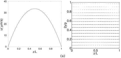
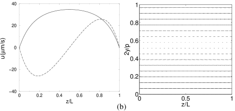
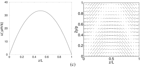

Figure 1b compares the case when the full equations of motion, including back-flow, are solved. The velocity is similar in magnitude, and the parabola flattens. This effect becomes more pronounced with an increase in the system size (Fig. 2). Our results are consistent with the picture described in De Gennes and Prost[1] (although these authors consider pinned director boundary conditions) that the velocity profile in a wide system will be flat, decaying to zero near the boundaries in a length of order the pitch of the cholesteric helix to satisfy the no-slip conditions on the velocity. Also in this case the cholesteric helix drifts with the flow. A significant effect of the back-flow is that there is much less bending of the helix, the pitch remaining constant across the system.

In the steady state we also find a secondary flow, of odd parity in , along the direction, which attains its maxima (in absolute value) close to the boundaries, and is zero in the center of the channel. The magnitude of this flow is comparable to the maximum fluid velocity along and it gives rise to shear forces which allow Eq. 3 to be balanced with a smaller director field deformation.
Now consider the case where the director is pinned at the wall (in such a way that there is no frustration in the helix when the system is at rest). Figure 1c shows the case without back-flow. The velocity field is, as expected, identical to that in Figure 1a because the director is having no effect on the flow. The helical texture is however much more deformed with a substantial component along . This occurs because the director configuration is unable to drift with the flow and thus the term (in Eq. (3)) requires a larger balancing molecular field.
When back-flow is turned on for this case there is a striking difference in the velocity profile. The net velocity is zero, to within the accuracy of the simulations (as would be expected from approximate analytic treatments [1, 4].) Secondary flow is important: it is bigger than the maximum velocity attained in the primary flow. Because the velocities in the system are very small the director field remains very close to its zero-flow configuration.
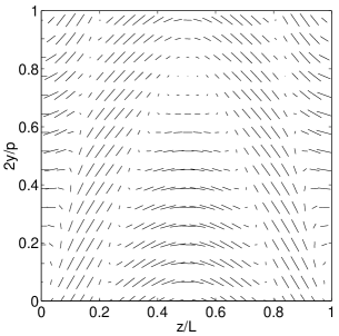
We now consider what happens as the pressure difference is increased. First the chevrons gradually become more bent until a threshold forcing at which a new structure appears. This structure, shown in Figure 3, has a flow-induced twist in the -direction. (The solution pictured in Figure 1c corresponds to the threshold between the chevron and the double twisted texture.) The period of the twist along is roughly equal to the natural twist of the cholesteric liquid crystal. This double twist structure was found for both flow-aligning (typically found in display devices) and flow tumbling (used in some rheological experiments[9]) viscosity regimes.
The maximum fluid velocity beyond which double twist appears depends sensitively on the system parameters. It is consistently smaller if fixed boundary conditions are used. For example, for pN, , and m, with fixed boundary conditions the velocity threshold is while for free boundaries it is an order of magnitude bigger. As increases, the threshold velocity decreases if fixed boundaries are used. This effect is somewhat less pronounced with free boundaries. The crossover between chevrons and double twist is smooth; even at weak forcing one can identify a small twist deformation in the direction.
It is possible to explain qualitatively the appearance of a double twist by again looking at Eq. 3. Let us consider the case of anchored boundaries. Near the center of the channel, the solution is still determined by balancing the molecular field with , but since the flow is faster, the bending of the chevrons become progressively more enhanced. When the deformation is such that two regions ordered along are a distance apart along the axis, a doubly twisted state is expected to be more stable. Such a texture is reminiscent of the doubly twisted cylinders which are the basic constituents of blue phases[1]. Indeed, in the case of no back-flow, where the simulations are stable for faster flows, a stack of such doubly twisted cylinders, separated by a regular array of defects, is stabilized by a large enough forcing.
Our results suggest that in real experiments[5, 6, 9], for slow flows, the helix is likely pinned to its initial configuration (e.g. by irregularities), so that the situation is close to that in Figure 1d and the viscosity is very large. If the pressure difference is increased, either the pinning is destroyed or a double twist forms. In both cases the viscosity would decrease as observed experimentally.
In conclusion, we have presented lattice Boltzmann simulations able to successfully simulate Poiseuille flow in cholesteric liquid crystals in the permeation mode. For weak forcing, if the cholesteric helix is pinned at the boundaries, we find a remarkable increase in the viscosity. With free boundaries there is a plug-like velocity profile in which the helix drifts with the flow. Beyond a threshold, dependent on system parameters, the flow distorts the helix much more giving rise to a doubly twisted director pattern. This approach could also be used to investigate, for the first time, the rheology of blue phases. Predictions can tested with present day microchannel experiments. In particular a fast Poiseuille flow may provide a novel method of inducing double twist in a liquid crystal texture thus allowing controlled experiments on blue phases in cholesterics.
This work was supported by EPSRC grant no. GR/R83712/01.
REFERENCES
- [1] P. G. de Gennes and J. Prost, The Physics of Liquid Crystals, 2nd Ed., Clarendon Press, Oxford (1993).
- [2] S. Chandrasekhar, Liquid Crystals, Cambridge University Press, (1980).
- [3] E. Grelet, S. Fraden, Phys. Rev. Lett. 90, 198302 (2003).
- [4] W. Helfrich, Phys. Rev. Lett. 23, 372 (1969); T. C. Lubensky, Phys. Rev. A 6, 452 (1969).
- [5] R. S. Porter, E. M. Barrall, J. F. Johnson, J. Chem. Phys. 45, 1452 (1966).
- [6] N. Scaramuzza, F. Simoni, R. Bartolino, Phys. Rev. Lett. 53, 2246 (1984).
- [7] A. D. Rey, J. Rheol. 46, 225 (2002); J. Rheol. 44, 855 (2000); Phys. Rev. E 65, 022701 (2002).
- [8] J Prost, Y. Pomeau, E. Guyon, J. Phys. II 1, 289 (1991).
- [9] K. Hongladarom, V. Secakusuma, W. R. Burghardt, J Rheol. 38, 1505 (1994).
- [10] See e.g. A. N. Shalaginov, L. D. Hazelwood, T. J. Sluckin, Phys. Rev. E 60, 4199 (1999).
- [11] A. N. Beris, B. J. Edwards, Thermodynamics of Flowing Systems, Oxford University Press, Oxford (1994).
- [12] C. Denniston, E. Orlandini, J. M. Yeomans, Europhys. Lett. 52, 481 (2000); Phys. Rev. E 63, 056702 (2001); G. Toth, C. Denniston, J. M. Yeomans, Comput. Phys. Comm. 147, 7 (2002).
- [13] C. Denniston, D. Marenduzzo, E. Orlandini, J. M. Yeomans, condmat/0312123; J. Jung, C. Denniston, E. Orlandini, J. M. Yeomans, Liq. Cryst. 30, 1455 (2003).