Impurity-enhanced Aharonov-Bohm effect in neutral quantum-ring magnetoexcitons
Abstract
We study the role of impurity scattering on the photoluminescence (PL) emission of polarized magnetoexcitons. We consider systems where both the electron and hole are confined on a ring structure (quantum rings) as well as on a type-II quantum dot. Despite their neutral character, excitons exhibit strong modulation of energy and oscillator strength in the presence of magnetic fields. Scattering impurities enhance the PL intensity on otherwise “dark” magnetic field windows and non-zero PL emission appears for a wide magnetic field range even at zero temperature. For higher temperatures, impurity-induced anticrossings on the excitonic spectrum lead to unexpected peaks and valleys on the PL intensity as function of magnetic field. Such behavior is absent on ideal systems and can account for prominent features in recent experimental results.
pacs:
71.35.Ji, 78.67.HcI Introduction
A charged particle moving in a magnetic field acquires a phase proportional to the applied magnetic flux due to the quantum interference between different closed paths, giving rise to the long-studied Aharonov-Bohm effect (ABE). AharonovBohm This effect is specially important if the particle’s configuration space has a ring-like topology, since the interference effects will create flux-dependent phase differences of characteristic size, which can be clearly identified in experiments. AharonovBohmExp
An interesting issue appears when one considers a system of bound charged particles, forming a composite neutral object. An example of such system is a ring-confined exciton, an optically active electron-hole bound state with experimentally accessible characteristics.
The optical manifestations of such excitonic Aharonov-Bohm effect in semiconductor quantum-ring structures has received great attention from both theoretical Chaplik95 ; Kalameitsev98 ; Pereyra00 ; Romer_Raikh00 ; Romer_RaikhPSL00 ; Song_Ulloa ; Hu01 ; Govorov02 ; UlloaPE02 ; GovorovPE02 ; Maslov_Citrin03 ; Climente03 and experimental Lorke00 ; Bayer03 ; Ribeiro03 groups. Whereas one could imagine that no ABE should be expected for neutral particles, a small but non-vanishing ABE in neutral excitons confined in one-dimensional rings was theoretically proposed. Chaplik95 ; Romer_Raikh00 ; Romer_RaikhPSL00 In such systems, the exciton’s finite size allows for an internal polarization of the positive and negative charges in such a way that the magnetic flux phases acquired by the electron and hole do not cancel each other. The ABE amplitude in one-dimensional systems is shown to depend on the tunnelling amplitude of either electron or hole to the “opposite side” of the ring and is exponentially suppressed when this tunnelling amplitude decreases. Romer_Raikh00 ; Romer_RaikhPSL00
The ABE is further suppressed when a 2D “ring stripe” is considered and both electron and hole are confined by a finite width potential. Hu01 ; Song_Ulloa However, if different confining potentials for the electron and hole are considered in the structure, a strong effect is expected on the photoluminescence intensity (PLI). Govorov02 ; UlloaPE02 ; GovorovPE02 In this case, a net radial polarization of the exciton naturally exists and the ABE could be strong enough to be detected by photoluminescence (PL) experiments. The optical emission is predicted to oscillate as the ground-state angular momentum changes, generating a series of “dark” and “bright” PL emission regions as function of the magnetic flux. The same underlying principle applies in the study of the PL response in semiconductor quantum dots with type-II band alignment. Kalameitsev98 ; GovorovPE02 ; Janssens02 An enhancement of the ABE is also predicted when an in-plane electric field is applied. Maslov_Citrin03
ABE on charged Bayer03 and neutral excitons Ribeiro03 has been reported in recent beautiful experiments and found to be in general agreement with expectations. However, some of the findings remain not completely understood and interesting questions remain open. For example, the experimental field-dependent PL intensity does not fully agree with the expected result in quantum rings. Ribeiro03 ; Evaldo_priv Moreover, as the PL signal is collected from an ensemble of dots/rings over a large area, the role of impurities cannot be neglected.
In this paper, we discuss the effect of impurity scattering on the optical properties of quantum rings and study the influence of perturbative defects in the optical Aharonov-Bohm effect in these systems. Previous treatments of disorder effects in magnetoexcitons in quantum-rings have focused attention on the underlying dynamics of the electron-hole dipole moment. Maschke01 We choose a different approach, concentrating on the effects of symmetry-breaking in the optical emission intensity.
Our main results can be summarized as follows: even though impurity scattering leads to mixing of angular momentum states, signatures of the Aharonov-Bohm effect on a neutral exciton remain for significant impurity strengths. We further find that finite temperatures not only produce the monotonic smoothing of spectral features, but also induce additional characteristics in the PLI that can be attributed to impurity effects. In fact, this suggests the use of disorder-induced ABE features as a tool to probe into the impurity potentials and extract information on the confining strength and localization length of the hole and electron wavefunctions. Additionally, we will discuss how our results can account for recent experimental data on the PLI of type-II QDs. Ribeiro03
The paper is organized as follows: in section II we set our system of reference, based on experimentally realized quantum-ring systems. A general description of the models and main features is given on section III. The PL emission, the core result of the paper, is presented in section IV, while our overall conclusions are given in section V.
II Quantum ring-like systems
The class of systems we are interested in includes nanoscopic semiconductor ring-structures with typical carrier confining radius nm. The confining radii can be different for electrons and holes due to sample strain and different carrier masses, giving rise to a net radial polarization of the electron-hole pair. A natural assumption is that the radial confining width is small () for at least one of the carriers.
If both electrons and holes are strongly confined in the radial direction, the corresponding dynamics is essentially one-dimensional and can be described by two concentric rings as on the left panel in Fig. 1a (henceforth referred to as polarized quantum ring).

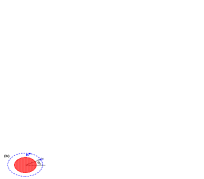
On the other hand, if only the outer carrier is strongly confined radially, then the inner carrier’s wavefunction has a more extended character and the system will have a type-II quantum dot characteristic distribution of carriers (Fig. 1b). In this situation, the confining potential profile is such that one of the carriers is confined inside the dot while the other is kept spatially separated on the outside. For disk-like quantum dots, the outside carrier is kept on a ring trajectory due to the Coulomb attraction between the carriers. In both cases, the polarized nature of the neutral exciton gives rise to oscillations on the ground state energy as the magnetic flux through the ring changes, due to the accumulation of a net Ahanonov-Bohm phase on the electron-hole pair wavefunction. Govorov02 ; UlloaPE02 ; GovorovPE02
The parameters used in the remaining of the paper model the experimental system described in the work of Ribeiro and collaborators. Ribeiro03 In that reference, Aharonov-Bohm oscillations on the PL energy for neutral magnetoexcitons were reported in InP/InAs self-assembled quantum dots. The band alignment is expected to be type-II, with the electron confined inside the disk-like quantum dot and the hole wavefunction localized on its outside due to the electrostatic potential barriers at the interface (as in Fig. 1b). We should also mention that built-in strains in these QD structures could result in an effective ring-like confinement potential for the electron as well (as in Fig. 1a). Tadic02 As such, we will study possible qualitative differences of the two situations and compare with experiments.
In order to compare our theoretical findings to the experimental data, we set the effective masses , , and ring radii nm and nm in our calculations. Those values for come from direct imaging of the structures as well as from fitting the observed spectral features. We also consider the experimental value for the size dispersion in the dots: nm, an important element in comparison with experiments.
For such parameters, typical single-particle confinement energy scales are meV. It is clear from the outset that if charged impurities with strong trapping potentials of order meV were present, the corresponding wavefunction localization would be so large that the Aharonov-Bohm oscillations could not survive. We then consider perturbative impurity effects, with weak potential strengths that may arise from local strain effects due to lattice mismatches, distant charge centers and other lattice defects near the InP/InAs interfaces. Evaldo_priv For concretness, we use the impurity potential strength as meV, and meV for holes and electrons, respectively, unless otherwise stated.
One should notice that even though our energy and length scales are set for comparison with the experiment, the validity of our results is not restricted to those parameters. In fact, as we will see, our predictions hold as long as .
III Theoretical Model
The system to be modelled displays a polarized neutral exciton confined on a 2D ring-like geometry and subjected to a perpendicular magnetic field. Depending on the structure, the geometry is that of a QR or an indirect type-II dot. We present the relevant potentials below.
In addition, we consider the effect of scattering impurities on the ring trajectories. Although we propose a relatively simple model for the exciton in the ring-like structure, it yields the necessary information for a qualitative comparison with experimental results.
III.1 Polarized Quantum Ring
We first consider the case where the confining width for both carriers is small compared to the ring radius and include single and multiple -scattering impurities along the confining region. The impurities are located on fixed angular positions (which can be different for electrons and holes). The Hamiltonian for the polarized Quantum Ring reads:
| (1) |
where are the electron (hole) effective masses, is the vector potential and are the electron (hole) impurity strengths. The last term is the Coulomb electron-hole interaction.
Following the discussion on section II, the effective Bohr radius for our reference system will be of order nm. Therefore, even though , we have if the radial confinement is strong (). Since our main interest resides on the impurity effects in strongly confined non-charged excitons (), the attractive interaction has a perturbative effect in the level structure and its main effect is to provide weak correlation effects and a constant binding energy shift , which we can safely ignore.
The “clean” () Hamiltonian is separable and can be solved analytically. The angular energies and eigenfunctions and are given by
| (2) |
| (3) |
where and are the electron (hole) confining radius and angular momentum value, respectively, are the individual fluxes and is the unit quantum flux. The energy levels of electron and hole on the ring are shown on the top panel of Fig. 2.
In this model, the excitonic states are given by a superposition of electron and hole states . These states have well-defined angular momentum values given by , and energies given by . The ground state angular momentum changes whenever either or is a half-integer. In a clean system, these angular momentum changes of the ground state result in sharp dark bright transitions in the PL of the QR. Govorov02
The impurities are included by numerical diagonalization of Hamiltonian (III.1) in this basis. The single-particle matrix elements can be calculated analytically, giving:
| (4) |
where , and is the angular position of the impurity, as shown on Fig. 1(b). From Eq. (4), one can readily see that the impurity potential breaks the rotational symmetry of the system since it couples all states. Thus, the excitonic states will no longer have definite angular momentum but rather be a linear combination of the form:
| (5) |
The effect of such symmetry breaking on the energy levels is seen in Fig. 2 in the case of a single impurity. All the level crossings at magnetic field values where , present in the clean system (top panel), become anticrossings with width proportional to , as shown in the bottom panel. It is worth mentioning that the spectrum remains unchanged under angular displacements of the single impurity, since only gives a phase to the matrix elements (4).

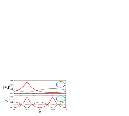
As a consequence of impurity scattering, both the hole and electron wavefunctions tend to be localized around . This effect is shown on Fig. 3 for the hole probability density for one impurity, as well as for the case of two impurities separated by a distance at . In the latter case, the wavefunction is pinned at and when and is repelled from these angles for . We find this pinning to be only weakly dependent on magnetic field.
III.2 Type-II Quantum Dots
The Hamiltonian for the type-II ring-confinement model reads:
| (6) |
where describes the electron confined in a parabolic dot with a characteristic frequency and under the influence of a magnetic field. In the absence of spin-orbit interactions, the electron energies are given by the Fock-Darwin levels:
| (7) |
where is a positive integer, is the angular momentum, is the cyclotron frequency and is the effective electron frequency. The Zeeman splitting term does not alter our results qualitatively and is disregarded in the following calculations.
We focus on impurity effects on the hole outside the QD. Notice that (i) the effects of impurity scattering are stronger on the 1D hole confinement as compared to the electronic 2D confinement and (ii) the ABE reflects the phase acquired by the hole wavefunction and would not be significatively affected by scattering processes inside the quantum dot.
The excitonic energy levels obtained from (6) in the strong confinement regime are shown in Fig. 4, for the cases with and without impurities. The low-lying states correspond to the combination of the first electronic states () with low-lying hole states. As in the polarized QR case, the impurity potential induces anticrossings on the whole spectrum, clearly seen in the right panel.

IV PL emission intensity
Once the spectral characteristics of the system are obtained, the photoluminescence emission intensity can be calculated. We consider optical interband transitions near the point of the solid. Since the photon angular momentum is taken up by the conduction-valence band transition matrix element, the emission intensity is proportional to the probability of finding the exciton on the state and also to the overlap between the electron and hole wavefunctions. The optical emission occurs then only if . This represents the selection rules on the electron emission. Govorov02 ; GovorovPE02 ; UlloaPE02 If the exciton is on state , the emission intensity is then given by:
| (8) |
with
| (9) |
and where is the projection of the excitonic state in the state, given by
| (10) |
In Eq. 8, is the electron-hole overlap radial integral. As discussed on section III.1, the wavefunctions tend to be localized near the impurities and such localization modifies the overlap integral , and therefore the emission intensity. However, once the wavefunctions are localized on the angular variable, the radial overlap has only a weak dependence with field, as long as the radial confinement is strong. Since we are interested on how the intensity changes with magnetic field, we take constant for simplicity since it does not alter our field-dependent results qualitatively.
The total emission intensity at a temperature will be given by the thermal population average over the emission from different states:
| (11) |
where and is the energy of the th excitonic state.
When impurities are considered, the total angular momentum is no longer a good quantum number since the impurity scattering mixes the angular momentum states. Therefore, a finite emission intensity is expected for all magnetic field values, unlike the situation in the clean system which exhibits sharp transitions to bright exciton states.
IV.1 Type II Quantum Dots
The plots on Fig. 5 show the photoluminescence intensity as function of the magnetic field for the type-II-quantum-dot magnetoexciton. For the clean case (shown in inset), a clear drop is seen after (T for nm), when the hole ground-state angular momentum changes from to . This is a consequence of the emission selection rules. For low temperatures, the emission comes mainly from the ground state and therefore the drop is more abrupt. For higher temperatures, the excited states contribute to the emission and the drop in intensity is smoother.
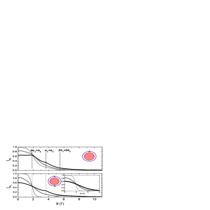
The presence of impurities changes this behavior qualitatively. The cases of both single and double symmetric defects are shown on the top and bottom panels of Fig. 5, respectively. The excitonic states are linear combinations of states with different , so that a non-zero component is present on the ground state even above . Therefore, the low temperature drop in the intensity is much less abrupt than in the clean case, as expected.
It is interesting, moreover, that at higher temperatures new PLI features arise when (). In the single impurity case, anticrossings occur at (involving the ground state and 1st excited state), and also at (between the first excited state and the second excited state) as shown in the left panel of Fig. 4. At these anticrossings, the components of the crossing states switch. If one of the crossing states had large component (i.e., “ character”) before the crossing, it will likely have a smaller component after the crossing. These changes in character for the first excited states give rise to small peaks or dips on the overall PLI at higher temperatures. At , for instance, as the ground state changes from “ character” to “ character”, the opposite happens to the first excited state. This “” character transition on the excited state will give a positive second-order contribution to the intensity. Most importantly, at , even though there is no ground state crossing, the second excited state has a “” change in character, which also manifests itself as a peak on the PLI for K (see spectrum in bottom panel on Fig. 4). On the other hand, this state’s character changes “” at , which in turn gives a negative contribution, seen as a sharp dip on the PLI at . These variations in PLI versus magnetic field at well-defined multiples of the AB flux provide then unique features that one can relate to the role of impurity/defect potentials affecting the exciton.
For the special case of two symmetrical impurities in the ring, an additional symmetry is introduced in the system: the coupling given by Eq. (4) vanishes whenever is an odd number. In terms of symmetry, such arrangement is equivalent to having an elongated ring instead of a circular one. As a consequence, the anticrossings at odd disappear while the ones at even remain. The effect on the intensity is that a plateau near zero intensity is seen for low temperatures between T () and T (), before the PLI grows again for T.
IV.2 Quantum Rings
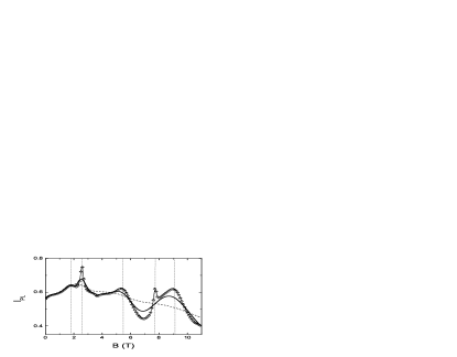
When both the hole and the electron are confined on a ring structure, the overall picture differs from the type-II quantum dot case. For the clean case and at zero temperature, the PLI displays sudden drops whenever the excitonic ground state angular momentum goes to states, i.e. whenever is a half-integer. This leads to a series of dark and bright exciton windows in magnetic field, Govorov02 shown as a dashed line on the top panel in Fig. 6. For higher temperatures, the thermal occupation of higher excitonic states smoothes out the transitions.
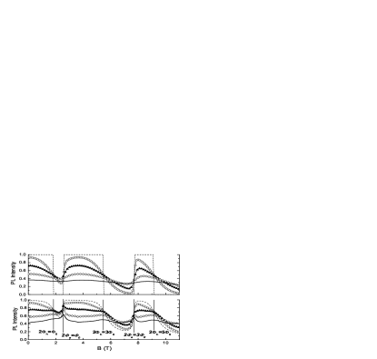
Impurity scattering changes this picture qualitatively in this spectrum as well, and introduces new field-dependent features on the PL intensity. As one impurity is added to the system, the PLI is non-zero for all magnetic field values even at zero-temperature, with a mean-value larger than in the clean case (dashed line on the bottom panel in Fig. 6). This is a direct consequence of angular momentum mixing since the ground state will always have an component for all values of magnetic field.
For higher temperatures, a pronounced peak appears at (T) due to a ground state anticrossing (see Fig. 2). Additional peaks and valleys can be seen for higher temperatures due to anticrossings in the excited states, in a similar fashion as to the type-II quantum-dot case. However, an important difference is that peaks are seen for magnetic field values where either or is a half-integer. The features for electrons are sharper due to their smaller mass and steeper level dispersions.
These findings could contribute to the understanding of recent experimental results on photoluminescence of neutral excitons in InP/GaAs type-II quantum dots. Ribeiro03 ; Evaldo_priv Fluctuations on the PLI are found at magnetic values which are delayed with respect to . These magnetic field values would correspond well to changes in had the electron been on a ring structure with a radius equal to the estimated QD radius . Such structure could come from deformations in the conduction band near the dot’s edge caused by strain effects. Tadic02 Our results show that the presence of impurities and the effective QR structure would give rise to fluctuations at these magnetic fields.
Such features on the PL intensity could also be used to have an experimental access into the characteristics of the disorder potential. The size of the energy gaps in the spectrum (Fig. 2) are directly related to the impurity strength . The results presented in this section use meV and meV, which yields gaps of about meV for electrons and meV for holes. Although fine tuning of those parameters is clearly possible, it is interesting that such relatively small values lead to strong modifications of the exciton spectra.
There is an additional important consideration. The results so far consider a single polarized QR and a pertinent inquiry is what would be the effect of the size distribution of the structures used in experiments. We can consider these effects assuming a ring ensemble with gaussian distributed radii (Fig. 7). As a general trend, a broad size distribution tends to blur the impurity effects, specially at higher magnetic fields. However, if the size distribution is as found in experiments (), these impurity-related effects are still seen for magnetic field values of order (T). We should especially mention that peaks in the PLI at certain flux values are quite robust to ensemble average, even as the dark/bright exciton transitions are made smoother.
We summarize this discussion by saying that the systematics of this behavior, robustness to ensemble average and temperature effects, and even qualitative agreement with experiment, definitively point out for an effective QR geometry of the system.
V Concluding Remarks
We have considered the effects of disorder on the Aharonov-Bohm effect in the optical emission of type-II quantum dots and quantum rings. As a general trend, the scattering potential breaks the rotational symmetry, thus coupling the angular momentum states. The effect of weak impurities does not preclude the Aharonov-Bohm oscillations in the optical spectrum, but rather induces additional features on the photoluminescence intensity at certain magnetic field values. Experimental systems have routinely high mobilities, yet some disorder is present and these PLI features could provide additional information on the structure of the impurity potential. They can also be used to probe the symmetries of the quantum rings, allowing, for example, one to discern between a circular structure and an elongated one.
Furthermore, our results could give insights on unexplained experimental results seen on the Aharonov-Bohm effect in neutral InP type-II quantum dot excitons. Ribeiro03 Our analysis suggests that the unexpected magnetic field behavior of the intensity seen in the experiment could be explained if disorder and specific confinement of electrons and holes are taken into account.
Acknowledgements.
We would like to thank Evaldo Ribeiro, Gilberto Medeiros-Ribeiro and Mikhail Raikh for valuable conversations and suggestions. This work was supported by FAPESP (grants 01/14276-0 and 03/03987-9), the US DOE (grant DE-FG02-91ER45334) and the Volkswagen Foundation.References
- (1) Y. Aharonov and D. Bohm, Phys. Rev., 115, 485 (1959).
- (2) R.G. Chambers, Phys. Rev. Lett. 5 3 (1960); A. Tonomura et al. Phys. Rev. Lett. 48, 1443 (1982); R. A. Webb et al. Phys. Rev. Lett. 54, 2696 (1985); For a review, see M. Peshkin, A. Tonomura, The Aharonov-Bohm Effect in Lecture Notes in Physics 340 (Springer-Verlag, Berlin, 1989).
- (3) A.O. Govorov, A.V. Chaplik, JETP Lett. 66, 454 (1997) .
- (4) P. Pereyra, S.E. Ulloa, Phys. Rev. B 61, 2128 (2000).
- (5) A.V. Chaplik, JETP Lett. 62, 900 (1995).
- (6) R.A. Römer, M.E. Raikh, Phys. Rev. B 62, 7045 (2000).
- (7) R.A. Römer, M.E. Raikh, Phys. Stat. Sol. B 221, 535 (2000).
- (8) J. Song, S.E. Ulloa, Phys. Rev. B 63, 125302 (2001).
- (9) H. Hu, J.-L. Zhu, D.-J. Li and J.-J Xiong, Phys. Rev. B 63, 195307 (2001).
- (10) A.O. Govorov, S.E. Ulloa, K. Karrai, R.J. Warburton, Phys. Rev. B 66, 081309(R) (2002)
- (11) S.E. Ulloa, A.O. Govorov, A.B. Kalameitsev, R.J. Warburton, K. Karrai, Physica E 12, 790 (2002).
- (12) A.O. Govorov, A.B. Kalameitsev, R.J. Warburton, K. Karrai, S.E. Ulloa, Physica E 13, 297 (2002).
- (13) A.B. Kalameitsev, V.M. Kovalev, A.O. Govorov, JETP Lett. 68, 669 (1998).
- (14) A.V. Maslov, D.S. Citrin, Phys. Rev. B 67, 121304(R) (2003).
- (15) J.I. Climente, J. Planelles, W. Jaskolski, Phys. Rev. B 68, 075307 (2003).
- (16) A. Lorke, R.J. Luyken, A.O. Govorov, J.P. Kotthaus, J.M. Garcia, P.M. Petroff, Phys. Rev. Lett. 84, 2223 (2000).
- (17) M. Bayer, M. Korkusinski, P. Hawrylak, T. Gutbrod, M. Michel, and A. Forchel, Phys. Rev. Lett. 90, 186801 (2003).
- (18) E. Ribeiro, G. Medeiros-Ribeiro, W. Carvalho Jr., A.O.Govorov, to appear in Phys. Rev. Lett. (2004) (for intensity fluctuations, see ver. 1 on cond-mat/0304092).
- (19) K.L. Janssens, B. Partoens, and F. M. Peeters, Phys. Rev. B 66, 075314 (2002).
- (20) K. Maschke, T. Meier, P. Thomas, S.W. Koch, Eur. Phys. J. B 19, 599 (2001).
- (21) M. Tadic, F.M. Peeters, K.L. Janssens. M. Korkusinski, P. Hawrylak, J. App. Phys. 92, 5819 (2002).
- (22) E. Ribeiro, G. Medeiros-Ribeiro (private communication).