Photonic crystal polarizers and polarizing beam splitters
Abstract
We have experimentally demonstrated polarizers and polarizing beam splitters based on microwave-scale two-dimensional photonic crystals. Using polarized microwaves within certain frequency bands, we have observed a squared-sinusoid (Malus) transmission law when using the photonic crystal as a polarizer. The photonic crystal also functions as a polarizing beamsplitter; in this configuration it can be engineered to split incident polarizations in either order, making it more versatile than conventional, Brewster-angle beamsplitters.
pacs:
42.25.Ja, 42.70.Qs, 41.20.JbPhotonic crystals are periodic dielectric structures that possess a unique band structure for electromagnetic (EM) waves. Their periodic boundary conditions produce multiple Bragg reflections, preventing the propagation of radiation within certain frequency and wavevector bands. In general, the specific characteristics of the band structure of a photonic crystal depend strongly on its geometry and material composition. A diverse set of applications has been proposed for photonic crystalsreview-reference , including suppression of spontaneous emission Yablonovitch1987 and optical waveguides Cregan1999 ; Chow2000 .
Although scalar approximations are usually adequate for electronic band structure calculations in solid-state materials, the vector nature of EM radiation must be taken into account when physically modelling photonic crystals. In particular, the transmission properties of a photonic crystal depend on its orientation relative to the polarization of the incident fields. Polarization-dependent band gap characteristics have been experimentally observed for propagation in the plane of periodicity in both slab and bulk two-dimensional (2D) photonic crystals Chow2000 ; Foteinopoulou2001 ; Hickmann2002 . While both of these structures possess periodicity in two dimensions, slabs are thin in their extruded (nonperiodic) dimension compared with the lattice constant, whereas bulk crystals are much larger in their extruded dimension than the lattice spacing. In bulk crystals, the band gaps for both incident polarizations are well-formed, although the center frequency, depth, width, and shape depend on the polarization Hickmann2002 . Slab crystals have a well-defined band gap for only one polarization and show only a small, incomplete band gap for the other Joannopoulos1999 .
The polarization properties associated with the band structure of a 2D crystal can be qualitatively understood considering the anisotropy of the lattice. In particular, each polarization experiences different boundary conditions depending on whether it is parallel or perpendicular to the plane of symmetry. Thus, the Fresnel coefficients are different for the two possible polarizations at each dielectric interface, even at normal incidence. These birefrigent properties have been recently exploited in the construction of a compact new kind of photonic crystal waveplate capable of controlling the polarization of light in transparent spectral regions Solli2002b .
In this work, we report a proof of principle experiment demonstrating a polarizer and a polarizing beam splitter (PBS) based on a bulk 2D photonic crystal, using microwave radiation. We show that a 2D photonic crystal can act as a polarizer if there is sufficient separation between the band gaps for different light polarizations. For the frequency ranges in which the band gaps do not overlap, one polarization is transmitted while the other is reflected. The quality of this type of polarizer depends on the transmission contrast and absolute transmission in the frequency region in question, and its useful bandwidth is determined by the frequency width of the non-overlap region. Photonic crystal polarization splitters have been suggested before Ohtera1999 ; however, emphasis was placed on the fabrication of a specific photonic crystal structure and no new direct experimental verification of the operation of the polarizer was presented. In addition, the novelty of a Brewster-independent polarizing beamsplitter was not discussed. It is also important to note that the results presented in our work were obtained with significantly lower index contrast in the dielectric materials.
We constructed the photonic crystals used in this experiment with a method described elsewhere Hickmann2002 . In short, hollow acrylic pipes (refraction index Gray1972 ) stacked in a triangular array form a bulk hexagonal lattice whose air-filling fraction (AFF) and lattice spacing are determined by the inner and outer diameters of the pipes. The crystals used in this experiment had a lattice spacing of 1/2 inch, with an AFF of 0.60. We tested crystals ranging from two to twenty layers. The scale of these crystals allows us to build them with extremely high precision and a large number of layers.
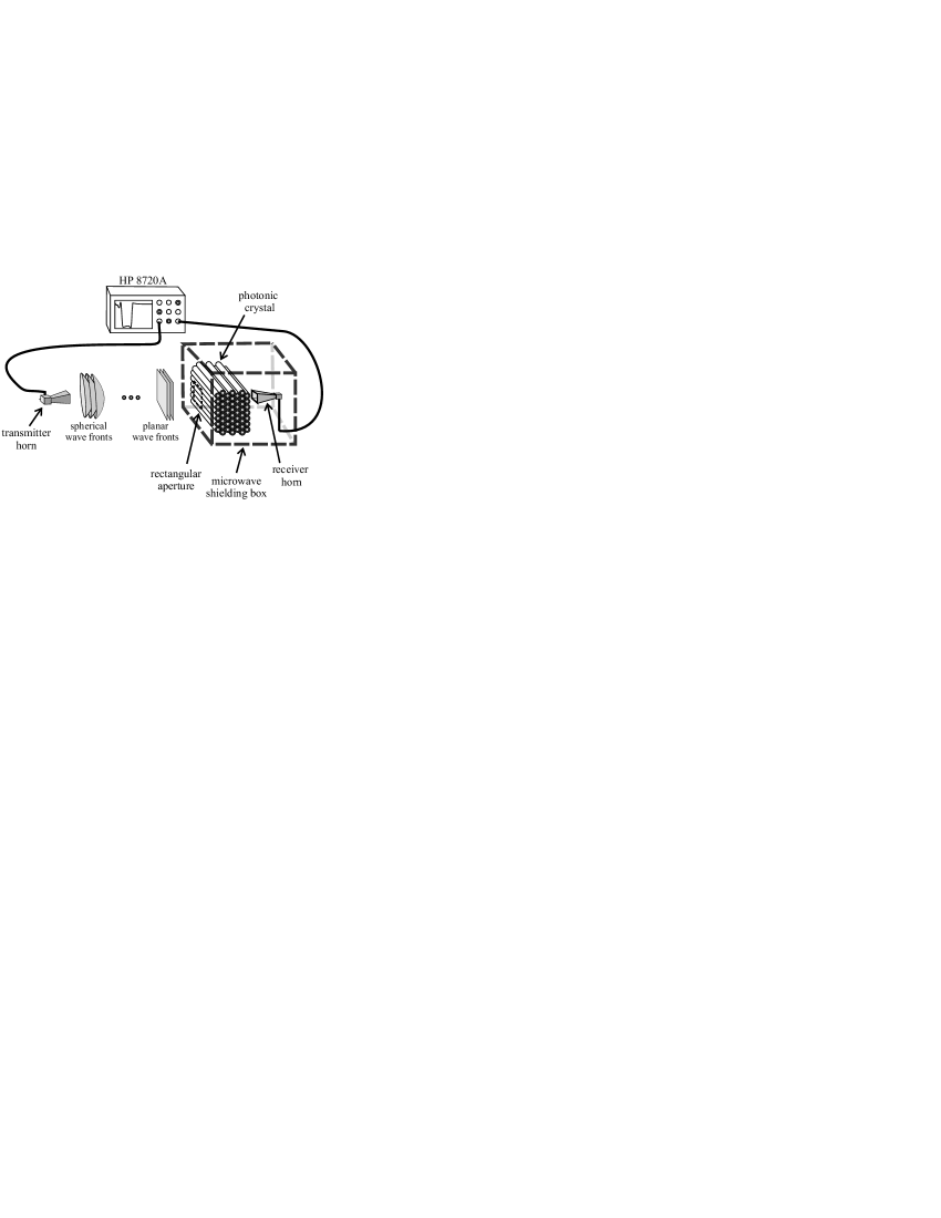
We measured the transmission through the crystals using a method that has also been previously described Hickmann2002 . Polarization-sensitive transmitter and receiver horns were used to couple microwaves between free space and an HP 8720A vector network analyzer (VNA). The crystal was positioned inside a microwave-shielded box with an aperture 14 cm 17 cm, deep in the far field (1.6 m) of the transmitter horn. The crystal is oriented so that the microwaves are incident in the direction Foteinopoulou2001 . The receiver horn was placed inside the box, centered directly behind the crystal in line with the transmitter and aperture. Since the crystal was far from the transmitter compared with the relevant wavelengths, the microwaves incident upon the crystal were effectively plane waves with a well-defined linear polarization. We confirmed this by measuring the transmission between crossed horns in the absence of the photonic crystal, finding a power suppression of 35 dB relative to the aligned configuration. A schematic of the experimental setup is presented in Fig. 1.
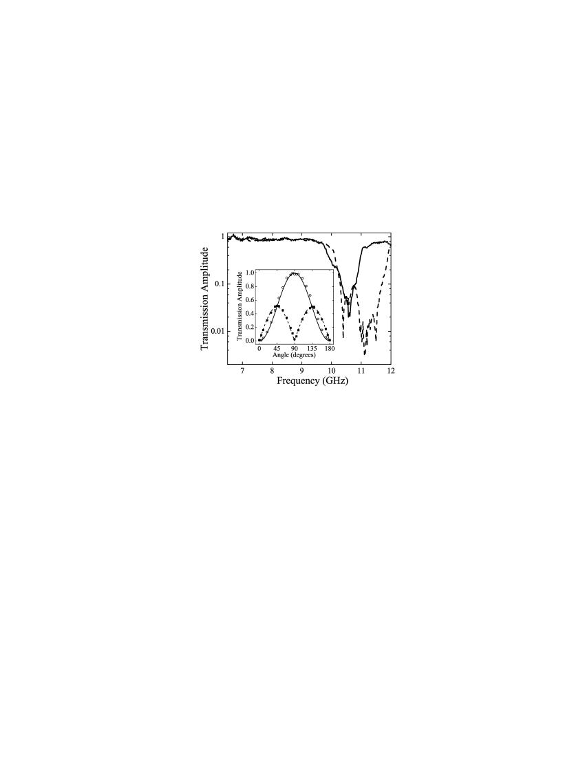
The fundamental band gap for our crystal is centered at roughly 11 GHz for transverse magnetic (TM) waves and 10.5 GHz for transverse electric (TE) waves. We label the polarizations TM and TE with respect to the plane of periodicity of the crystal; thus the electric field is perpendicular to the pipes for TM polarized waves and parallel to the pipes for TE polarized waves. The band gap depth and width also depend on polarization. There is a clear region of non-overlap around 11.4 GHz, in which TM radiation is strongly reflected and TE radiation is primarily transmitted (see Fig. 2).
In order to verify the operation of the crystal as a linear polarizer, we fixed the crystal orientation and simultaneously rotated both horns around the axis of propagation. If the horns are kept parallel during the rotation, this is equivalent to fixing the horns and rotating the crystal. Since the horns are polarization-sensitive, this operation should give a measured transmitted field of
| (1) |
where is the incident electric field amplitude and is the rotation angle defined such that at the radiation detected by the receiver horn corresponds to pure TM polarized waves. We also performed this experiment with the horns perpendicular (crossed), in which case simultaneous rotation gives
| (2) |
The results of these experiments, normalized to a maximum of unity transmission, are shown in the inset of Fig. 2. In both cases, the data agree very well with the expected polarizer relations of Eqs. 1 and 2. The intensity transmission at 0 degrees with the horns parallel was 0.0036% of the incident radiation, and the maximum to minimum transmitted power ratio was roughly 15,000:1, limited by our experimental resolution.
We note that the maximum external transmission of TE polarized radiation at 11.4 GHz was only . This power loss is due in part to external reflections from the crystal faces. The remainder arises because the transmission through a photonic crystal at fixed frequencies outside the band gap displays oscillatory properties as a function of the number of layers in the structure. These effects do not represent a fundamental limit to the quality of photonic crystal linear polarizer devices, because with proper engineering and a greater number of layers these values will improve.
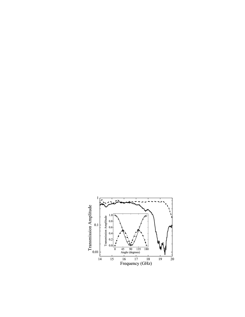
In addition to the fundamental band gap, we observed the next higher order or double-frequency band gap in our structure (see Fig. 3). This gap is centered at roughly twice the frequency of the fundamental and has approximately twice the width. Its average depth appears greater, which can be qualitatively understood based on the increased optical path length at this frequency.
We repeated the above experiments between 19.1 and 19.2 GHz (within this double-frequency band gap) to verify the operation of the linear polarizer at higher-order band gaps. An interesting feature in this region is that the band gaps have an appreciable non-overlap region to the red (in addition to the one to the blue) in which TM radiation is transmitted and TE radiation is reflected. Because of this inverted reflection/transmission relation, the maximum transmission with the horns aligned should occur at 0 and 180∘ (using the same angle convention as before) rather than 90∘. With the horns crossed, the angular dependence should again be given by Eq. 2. The results of these measurements (again normalized to a maximum of unity transmission) are shown in Fig. 3 along with the relevant TM and TE transmission spectra. In both cases, the data show the expected angular dependence. With the horns aligned, the intensity transmission at 90 degrees was 0.032% of the incident radiation, and the maximum to minimum power ratio was approximately 1,800:1.
It is worth noting that the photonic crystal polarizer discussed here differs from conventional linear polarizers because it reflects rather than absorbs the rejected polarization. In this sense, it is similar to a PBS. However, unlike conventional PBS devices, which operate by Brewster-angle reflections, this beam splitter can be engineered to split the polarizations in either order. As demonstrated above, by appropriately choosing a frequency region (or engineering a photonic crystal given a fixed frequency) the beam splitter can transmit either TE or TM radiation, while reflecting the other. Since this beam splitter does not rely on Brewster’s angle, the angle between the direction of propagation of the rejected polarization and the incident beam is not constrained. In fact, as demonstrated here, it works even at normal incidence. Because of the previous considerations, photonic crystal PBSs are much more versatile devices than conventional, Brewster-based beam splitters.
In designing photonic crystal polarizers and PBSs, it will be important to find or engineer structures with the correct band structure characteristics. To be useful as a polarizer, a photonic crystal should have a deep and wide band gap for at least one polarization. If the structure has band gaps for both independent polarizations, there must exist some frequency region in which they do not overlap, and the wider this region, the greater the useful bandwidth of the polarizer. Along these lines, it is also advantageous to utilize higher-order band gaps. They are generally deeper than the fundamental, and since their center frequencies occur at multiples of the fundamental frequency, their widths and relative separation for the two polarizations are greater.
In conclusion, we have demonstrated that photonic crystals can be used as linear polarizers and polarizing beam splitters by exploiting their polarization-dependent transmission and reflection properties. Since Maxwell’s equations are scale-invariant, all the microwave results presented here apply equally across the EM spectrum. We anticipate that these devices will have applications in situations requiring compact, tailored polarization control. They may be particularly useful in the optical region of the spectrum as integrated elements in photonic crystal circuits and related devices.
This work was supported by ARO grant number DAAD19-02-1-0276. We thank the UC Berkeley Astronomy Department, in particular Dr. R. Plambeck, for lending us the VNA. JMH thanks the support from Instituto do Milênio de Informação Quântica, CAPES, CNPq, FAPEAL, PRONEX-NEON, ANP-CTPETRO.
References
- (1) See for example, J. D. Joannopoulos, R. D. Meade and J. N. Winn, Photonic Crystals (Princeton University Press, Princeton, 1995).
- (2) E. Yablonovitch, Phys. Rev. Lett. 58, 2059 (1987).
- (3) R. F. Cregan, B. J. Mangan, J. C. Knight, T. A. Birks, P. St. J. Russell, P. J. Roberts, D. C. Allan, Science 285, 1537 (1999).
- (4) E. Chow, S. Y. Lin, S. G. Johnson, P. R. Villeneuve, J. D. Joannopoulos, J. R. Wendt, G. A. Vawter, W. Zubrzycki, H. Hou, and A. Alleman, Nature 407, 983 (2000).
- (5) S. Foteinopoulou, A. Rosenberg, M M. Sigalas, and C. M. Soukoulis, J. Appl. Phys. 89, 824 (2001).
- (6) J. M. Hickmann, D. Solli, C. F. McCormick, R. Plambeck, and R. Y. Chiao, J. Appl. Phys. 92, 6918 (2002).
- (7) S. G. Johnson, J. Fan, P. R. Villeneuve, J. D. Joannopoulos, and L. A. Kodziejski, Phys. Rev. B 60, 5751 (1999).
- (8) D. R. Solli, C. F. McCormick, R. Y. Chiao, and J. M. Hickmann, to appear in Appl. Phys. Lett. (2003).
- (9) D. Zhao, B. Shi, Z. Jiang, Y. Fan, and X. Wang, Appl. Phys. Lett. 81, 409 (2002).
- (10) Y. Ohtera, T. Sato, T. Kawashima, T. Tamamura, and S. Kawakami, Electron. Lett. 35, 1271 (1999).
- (11) AIP Handbook, 3rd ed., edited by D. E. Gray (McGraw-Hill, New York, 1972), p. 5-132.