Dielectric photonic crystal as medium with negative electric permittivity and magnetic permeability
Abstract
We show that a two-dimensional photonic crystal (PC) made from a non-magnetic dielectric is a left-handed material in the sense defined by Veselago. Namely, it has negative values of both the electric permittivity and the magnetic permeability in some frequency range. This follows from a recently proven general theorem. The negative values of and are found by a numerical simulation. Using these values we demonstrate the Veselago lens, a unique optical device predicted by Veselago. An approximate analytical theory is proposed to calculate the values of and from the PC band structure. It gives the results that are close to those obtained by the numerical simulation. The theory explains how a non-zero magnetization arises in a non-magnetic PC.
About 35 years ago Victor VeselagoVeselago (1967) considered theoretically propagation of the electromagnetic waves (EMW’s) in a hypothetical left-handed medium (LHM), where both the electric permittivity and the magnetic permeability are negative in some frequency range. Since the square of the speed of light is positive, the EMW’s propagate but they have unusual properties, like anomalous Doppler and Cherenkov effects, negative light pressure, and negative refraction (NR) at the interface with a regular medium. The latter property enables three-dimensional (3D) imaging. The origin of all these properties is the fact that the energy flux, S and the wave vector, k are antiparallel in the LHM. An important assumption of Veselago’s theory is the absence of spatial dispersion, which means that both and are -independent. However both of them are functions of frequency. A generalization of Veselago’s theory for the case of spatial dispersion would not be simple because in this case the expression for the Poynting vector includes an extra term Landau and Lifshitz (1960).
To create the LHM Veselago proposed to combine two independent different subsystems Veselago (1967), one with a negative and another with a negative . As an example, he considered a ferromagnetic metal at frequency close to the ferromagnetic resonance and below the plasma frequency of the metal. Following this line, the San Diego groupShelby et al. (2001) has observed a NR in an artificial composite system and attributed this effect to a two-dimensional (2D) LHM. Their system consists of two elements: 2D metallic photonic crystal (PC) creating negative below a cutoff frequency and the so-called split-ring resonators creating negative due to anomalous dispersion near the resonance. The experiments of the San Diego group are very important because they have ignited the whole field, started by Veselago about 35 years ago but completely forgotten since then. However they caused new hot debates concerning different aspects of their experiments and interpretationsPokrovsky and Efros (2002a); Valanju et al. (2002); Smith et al. (2002a, b); Garcia and Nieto-Vesperinas (2002).
Many groupsKosaka et al. (1998); Notomi (2000); Luo et al. (2002a, b); Cubukcu et al. (2003) predicted and observed NR in PC’s using for the prediction the dispersion relation of EMW’s and methods of geometrical optics. However, the “effective refractive index” they found was, in general, a function of . We think that it originates from the spatial dispersion of the dielectric constant for EMW with deep in the Brillouin zone. Several authorsKosaka et al. (1998); Notomi (2000); Luo et al. (2002b) found that near the point this index becomes -independent. As we show below, together with the negative group velocity this indeed is a manifestation of the LHM.
The main idea of this work is based upon the theorem proved in Ref. Pokrovsky and Efros (2002b). It reads that the group velocity in an isotropic medium is positive in the regular media (RM)(, ) and negative in the LHM. This means that vectors and are parallel in the RM and antiparallel in the LHM. This theorem follows from the thermodynamics requirement that the energy of electromagnetic fields is positive.
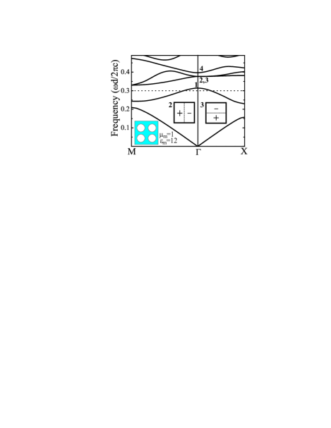
Now we generalize this theorem to a 2D PC illustrated in the left bottom inset of Fig. 1. The PC represents a square lattice of period , comprising cylindrical holes in a dielectric medium with the axes of cylinders along -direction. We consider propagation of EMW’s with the electric field in this direction (s-wave). The calculated weu low frequency spectrum of EMW’s in this PC is shown in Fig. 1 for the case when the dielectric material of the crystal is characterized by , . The fields in the PC are represented by the Bloch functions with a 2D wave vector =(, ). One can see from Fig. 1 that in the frequency range a little below the top of the band at the point, the group velocity is negative and there are no other bands in this frequency range. It is also important that band is not degenerate at -point. Near the -point the wavelength is much larger than the lattice period of the PC and one can introduce -independent and . Since -axis is the axis of symmetry, we have a uniaxial crystal and both tensors in the principal axes have only two components , and , respectively. The electromagnetic energy density of the s-wave can be represented in the formLandau and Lifshitz (1960)
| (1) |
where . In the rest of the paper we use notation , . Since we get , where 2D group velocity . Thus, negative means negative and vise versa. For the propagating waves it also means . It follows that this PC is a LHM in the frequency range under study.
Note, that the p-wave (magnetic field in direction) is characterized by and . These components might also be negative in the vicinity of the point but within a different frequency range.
We find and by microscopic calculations and show that they are indeed both negative in the frequency range under study. For this purpose we consider a PC slab infinite in -direction and embedded in a homogeneous medium with , . A 2D point source (an infinite dipole along -axis) is located in the homogeneous medium to the left of the slab. If we now choose and so that the cylindrical wave in the system is the same as it would be in a completely homogeneous medium with and (though inside the slab there is a microscopic field), the values of and obtained in this way are the macroscopic and of the slab at a given frequency. The best choice for and at the working frequency is obtained by a fitting procedure and the result is shown in Fig. 2. It yields , . Thus, at this frequency the PC slab is a LHM and this result is in accordance with the above theorem. Note, that in the case of the LHM the vectors S and k are in the opposite directions (see animation http://www.physics.utah.edu/ efros ).
One can calculate independently the refractive index of the slab from the dispersion relation of the band . At small it can be written in a form . Our calculation of spectrum gives , . Using the alternative definition of namely, one gets
| (2) |
Note, that as . At the working frequency , which agrees with and found above.
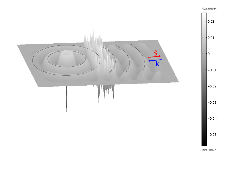
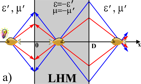
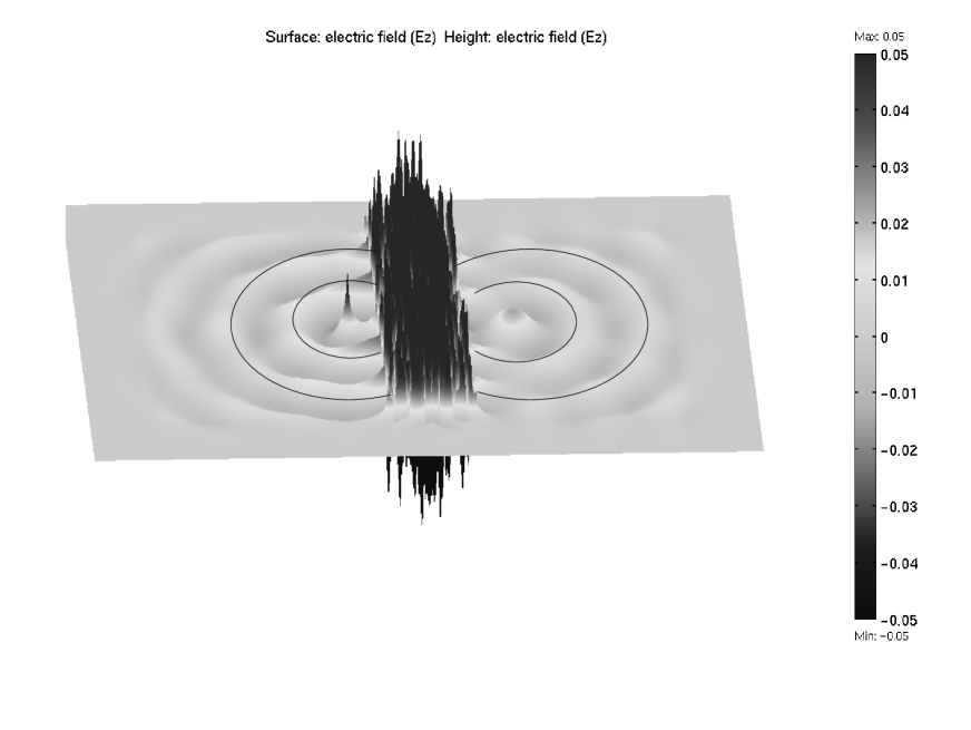
If we choose and as the parameters of the homogeneous medium surrounding the PC, we obtain a unique device proposed by VeselagoVeselago (1967) that we call the Veselago lens. It is shown schematically in Fig. 3a. The computer simulation of the Veselago lens is shown in Fig. 4 (also see animation http://www.physics.utah.edu/ efros ). In the above simulations the PC is cut in the direction . We have checked that the results do not change if the PC is cut in the direction . This confirms the absence of spatial dispersion at the working frequency. The size of the focus is of the order of the wavelength as predicted by the diffraction theory Pokrovsky and Efros (2002c).
Now we explain how the starting theorem that follows from Eq.(1) and is formulated in terms of macroscopic electrodynamics can be interpreted microscopically. The negative group velocity shown at Fig. 1 results from the repulsion of bands and , . Therefore a microscopic explanation of negative should be found in terms of the interaction between these bands. We propose a quantitative explanation by writing Maxwell’s equation for the microscopic field in a matrix formJoannopoulos et al. (1995); Sakoda (2001) in the basis of Bloch functions at . Taking into account that near the -point the bands , , , are far from the other bands, we truncate the matrix keeping only these four bands. This approximation is analogous to the Kane model in semiconductor physicsKane (1957). By diagonalizing the truncated matrix we find the spectra of all four bands and the correct combinations of basis functions for each band at finite . We have checked that the dispersion law for all bands - as obtained from the truncated model does not differ by more than from the result presented in Fig. 1 at . At small the microscopic electric field for the band has the form
| (3) |
where is the 2D-vector, , , and are the Bloch functions at , the positive parameters , have the dimensionality of a wave vector and they are integrals from these functions. The symmetry of the function is . The function has symmetry. The functions and have the symmetries and respectively. The parity of and functions within the elementary cell is shown in the central inset of Fig. 1.
If the material of the PC were metallic, the electric field in the bands and would create two currents in opposite directions. These currents would induce a magnetic moment in and directions. In case of the dielectric PC these currents are imaginary displacement currents and they do not create any magnetic moment in the modes and . However, as follows from Eq.(3) the admixture of bands and to band is also imaginary. Therefore the band has a real magnetic moment.
The magnetization can be calculated using the expression
| (4) |
where , is a unit vector in direction, inside the holes and otherwise, the integration is performed over the unit cell, and is given by Eq.(3). Only the second and the third terms from Eq.(3) contribute to the magnetization. The result can be expressed through the integrals from and . These functions have been taken from the computation of the spectrum shown at Fig. 1. The macroscopic vectors and are connected by the relation , where and means averaging over the unit cell. Only the function gives a non-zero contribution after the averaging. It gives the main contribution to . Other basis functions give non-zero contribution only when multiplied by -dependent terms in the expansion of the within the unit cell. Their contributions to are of the same order in but they are much smaller than the contribution from since , where and are the frequencies of the bands and at . In fact, the latter strong inequality permits truncation of the matrix in our analytical model.
Now we can find from the definition . The result is
| (5) |
Comparing Eq.(2) and Eq.(5) one can see that the root of at is responsible for the root of . This means that is non-zero and negative at . On the other hand, changes its sign at . Thus, the gap at is due to . At one gets and that is very close to the value obtained above by the fitting procedure. Thus, we have found analytically the value of .
The 3D LHM can be obtained in the same way, for example, using the PC with the cubic symmetry proposed by Luo et al.Luo et al. (2002b). This PC also has a negative group velocity near the point with no other bands at this frequency.
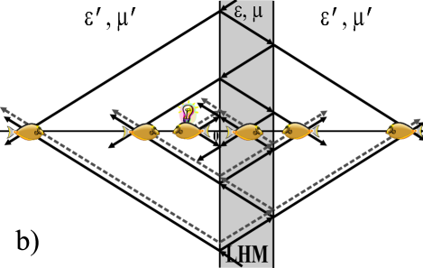
Thus, we have shown that the LHM can be readily obtained using only one dielectric PC that creates both negative and . We have presented the physical explanation of this phenomenon in a 2D case. The working frequency can be easily changed in a wide range by changing the lattice constant and of the PC. It is important for applications that the losses in a dielectric PC are much smaller than in a metallic one. We have found not only but also and that are necessary to describe the dynamical properties of the interfaces. This is especially important for the creation of the Veselago lens, which requires no reflection at interfaces, thus imposing two matching conditions on and . By matching only one gets a modification of the Veselago lens with multiple foci (Fig. 3b)Pokrovsky and Efros (2002d). We realize, that we have not presented a method of matching the LHM with the surrounding medium. This matching is very easy in computational approach but it must be handled creatively on the way toward real devices.
Acknowledgements.
We are grateful to Serge Luryi and Valy Vardeny for helpful discussions. The work has been funded by the NSF grant DMR-0102964.References
- Veselago (1967) V. G. Veselago, Sov. Phys.-Solid State 8, 2854 (1967).
- Landau and Lifshitz (1960) L. D. Landau and E. M. Lifshitz, Electrodynamics of Continuous Media (Pergamon Press, Oxford, 1960).
- Shelby et al. (2001) R. A. Shelby, D. R. Smith, and S. Schultz, Science 292, 77 (2001).
- Pokrovsky and Efros (2002a) A. L. Pokrovsky and A. L. Efros, Phys. Rev. Lett. 89, 093901 (2002a).
- Valanju et al. (2002) P. M. Valanju, R. M. Walser, and A. P. Valanju, Phys. Rev. Lett. 87, 187401 (2002).
- Smith et al. (2002a) D. R. Smith, S. Schultz, P. Markos, and C. M. Soukoulis, Phys. Rev. B 65, 195104 (2002a).
- Smith et al. (2002b) D. R. Smith, D. Schurig, and J. B. Pendry, Appl. Phys. Lett. 81, 2713 (2002b).
- Garcia and Nieto-Vesperinas (2002) N. Garcia and M. Nieto-Vesperinas, Opt. Lett. 27, 885 (2002).
- Kosaka et al. (1998) H. Kosaka, T. Kawashima, A. Tomita, M. Notomi, T. Tamamura, T. Sato, and S. Kawakami, Phys. Rev. B 58, 10096 (1998).
- Notomi (2000) M. Notomi, Phys. Rev. B 62, 10696 (2000).
- Luo et al. (2002a) C. Luo, S. G. Johnson, J. D. Joannopoulos, and J. B. Pendry, Phys. Rev. B 65, 201104(R) (2002a).
- Luo et al. (2002b) C. Luo, S. G. Johnson, J. D. Joannopoulos, and J. B. Pendry, Appl. Phys. Lett. 81, 2352 (2002b).
- Cubukcu et al. (2003) E. Cubukcu, K. Aydin, E. Ozbay, S. Foteinpolou, and C. M. Soukoulis, Nature 423, 604 (2003).
- Pokrovsky and Efros (2002b) A. L. Pokrovsky and A. L. Efros, Solid State Comm. 124, 283 (2002b).
- (15) All computations in this paper are performed using the commercially available software FEMLAB.
- (16) http://www.physics.utah.edu/ efros.
- Pokrovsky and Efros (2002c) A. L. Pokrovsky and A. L. Efros, Physica B (accepted for publication). Preprint at cond-mat/0202078 (2002c).
- Joannopoulos et al. (1995) J. Joannopoulos, R. Meade, and J. Win, Photonic crystals (Princeton Press, Princeton, NJ, 1995).
- Sakoda (2001) K. Sakoda, Optical properties of photonic crystals (Springer Verlag, 2001), p. 38.
- Kane (1957) E. O. Kane, J. Phys. Chem. Solids 1, 249 (1957).
- Pokrovsky and Efros (2002d) A. L. Pokrovsky and A. L. Efros, Appl. Optics (in press). Preprint at cond-mat/0212312 (2002d).