Direct Observation and Quantitative Analysis of Anti-ferroelectric Fluctuations in Pb(Mg1/3Nb2/3)O3 Relaxor
Abstract
Synchrotron x-ray scattering studies of anti-ferroelectric nanoregions (AFR) as fluctuations, which give rise to 1/2(hk0) superlattice reflections ( spots), were systematically performed in Pb(Mg1/3Nb2/3)O3 (PMN) ferroelectric relaxor. Separation of the spots from underlying diffuse scattering background allowed studying them as separate entities for the first time. AFR fluctuations were shown to be different from the chemical nanodomains (CND) and ferroelectric polar nano-regions (PNR). Instead, they are formed by anti-parallel short-range correlated Pb2+ displacements that lead to unit cell doubling in directions, based upon structure factor calculations. Correlation length is only on the 30 Å scale, which defines the effective average size of the AFR fluctuations. This size remains temperature independent while the total number of AFRs significantly increases near the Vogel-Fulcher freezing temperature of 220 K. Presence of local fluctuations produced by anti-parallel atomic displacements can explain relaxor behavior as a result of competition between ferroelectric and anti-ferroelectrics type polar ordering in the glass-like systems.
pacs:
77.84.Dy,77.80.Bh,77.90.+k,61.10.-iI Introduction
Pb(Mg1/3Nb2/3)O3 (PMN) belongs to a special class of relaxor ferroelectrics with average cubic perovskite ABO3 crystal structure Bonneau et al. (1991); de Mathan et al. (1991) (), where sites are occupied by Pb2+ and sites by a mixture of Nb5+ and Mg2+ ions Cross (1994). As-grown PMN single crystals exhibit excellent crystalline properties with mosaic spread . However, on the nanometer scale there is a significant degree of chemical and displacement disorder Husson et al. (1988); Hilton et al. (1990); Cross (1994); Akbas and Davies (2000); Egami et al. (1997, 1998); Burns and Dacol (1983); de Mathan et al. (1991); Bonneau et al. (1991); Chernyshev and Zhukov (1998); Vakhrushev et al. (1989); Blinc et al. (2000); Lebedinskaya et al. (2001); Miao et al. (2002); Dkhil et al. (2002); Krause and Gibbon (1971). Moreover, atoms on the sites are short-range ordered within kinetically quenched-in chemical nanodomains (CND) with symmetry Krause and Gibbon (1971); Husson et al. (1988); Egami et al. (1997); Hilton et al. (1990); Akbas and Davies (2000); Egami et al. (1998).
Strong frequency dispersion of real and imaginary parts of dielectric susceptibility is one of the most recognized properties that distinguish relaxors from ”normal ferroelectrics” Cross (1994). Temperature dependence of the dielectric constant in PMN exhibits a broad peak at 265 K with a magnitude exceeding 30,000 when measured under AC electric field Cross (1994). Both magnitude and position of the peak strongly depend on frequency, which results in shifts of the dielectric peak maximum towards 220 K as approaches zero Viehland et al. (1991); Cross (1994).
Additionally, degree of dispersion, size of CND and structural transitions can be controlled in PMN by various atomic substitutions on both and sites. For example, Ti doping leads to formation of (PMN-xPT) solid solutions, where relaxor properties diminish as PT doping increases and eventually disappear near morphotropic phase boundary corresponding to on the PMN-PT phase diagram Shrout et al. (1990); Chen (2000).
Contrarily to ”normal ferroelectrics”, in PMN there is no clear crystallographic evidence for any measurable spontaneous macroscopic structural phase transition in a wide (5-800 K) temperature interval Bonneau et al. (1991); de Mathan et al. (1991). Instead, it is believed that gradual freezing into nonergodic glass-like state is taking place below Viehland et al. (1991); Cross (1994); Colla et al. (1996); Vakhrushev et al. (1989); Dorogovtsev and Yushin (1990); Chen (2000); Dkhil and Kiat (2001). Nevertheless, small rhombohedral distortions Shebanov et al. (1984) and a change of slope in the temperature dependence of the lattice constant Dkhil et al. (2002) were also reported near from single crystal diffraction studies. It was also demonstrated that macroscopic ferroelectric structural phase transition can be induced in PMN(111) by applying external DC electric field with a magnitude above the critical value of E1.7 kV/cm Calvarin et al. (1995); Vakhrushev et al. (1997); Colla et al. (1996); Dkhil and Kiat (2001).
Several models were proposed to explain relaxor behaviors in Pb-containing perovskite compounds Cross (1994); Westphal et al. (1992); Viehland et al. (1991); Egami et al. (1998); Glazounov and Tagantsev (2000); Dorogovtsev and Yushin (1990). Current understanding of PMN relaxor properties relies on existence of polar nanoregions (PNR), possibly with rhombohedral symmetry Burns and Dacol (1983); de Mathan et al. (1991); Bonneau et al. (1991); Vakhrushev et al. (1995). These nanoregions are commonly envisioned as interacting ferroelectric fluctuations, which were proposed to nucleate below by Burns et al. Burns and Dacol (1983). Spherical-Random-Bond-Random-Field (SRBRF) model Blinc et al. (2000) is one of the latest theoretical treatments describing interactions between PNR in a self-consistent fashion. Alternatively, relaxor properties were attributed to special role of Pb atoms causing frustration of the local structure by displacements needed to accommodate lone electron pair of the Pb2+ ion in the presence of underlying chemical disorder Egami et al. (1998); Chen (2000).
Deviation of the local structure from the cubic average is expected due to the presence of aforementioned CND Husson et al. (1988); Hilton et al. (1990); Krause and Gibbon (1971); Egami et al. (1997); Vakhrushev et al. (1996); Zhang et al. (1996); Egami et al. (1998); Akbas and Davies (2000) and PNR Burns and Dacol (1983); Westphal et al. (1992); Viehland et al. (1991); Blinc et al. (2000); Gehring et al. (2001); Dkhil and Kiat (2001); Dkhil et al. (2002); Hirota et al. (2002); Wakimoto et al. (2002) nanoregions. Because their sizes are believed to be smaller than , it is a challenging task to study these nanoregions with inherently long-range order probing tools such as electron, neutron and x-ray diffraction. Nevertheless, it has been demonstrated that chemical short-range order within CND can be directly observed and studied in PMN single crystals by applying standard crystallographic techniques due to the presence of very weak and diffuse 1/2(hkl) type superlattice peaks, commonly called F spots in literature Krause and Gibbon (1971); Hilton et al. (1990); Husson et al. (1988); Vakhrushev et al. (1996); Zhang et al. (1996).
Various diffraction studies of the PMN have also reported the presence of strong diffuse scattering near fundamental Bragg reflections Vakhrushev et al. (1989); Hilton et al. (1990); Bonneau et al. (1991); de Mathan et al. (1991); Vakhrushev et al. (1995); You and Zhang (1997); You (2000); Dkhil et al. (2002); Miao et al. (2002). Quantitative analysis of temperature dependent neutron diffuse scattering near Bragg peaks has been attributed to polarization fluctuations, which could be related to aforementioned PNRs Vakhrushev et al. (1995). As a result, directions and relative magnitudes of the ionic displacements were determined and ferroelectric nature of parallel Pb2+ displacements has been established. However, calculated ionic displacement pattern did not have expected center of mass, required by dispalcements originating from optic vibrations. Alternatively, the anisotropic x-ray diffuse scattering near Bragg peaks, which have odd integer sum of the Miller indices, was attributed to pure transverse optic (TO) soft modes, which undergo q-dependent freezing within 190-260 K temperature range You and Zhang (1997); You (2000). Hirota et al. claimed to resolve controversy of the diffuse scatterings origin by introducing a phase-shifted soft mode model of PNRs Hirota et al. (2002). Moreover, recent inelastic neutron scattering experiments Naberezhnov et al. (1999); Gehring et al. (2001) identified presence of the TO soft mode above Td, which becomes overdamped at lower temperatures due to condensation of the PNRs Gehring et al. (2001). Interestingly, subsequent recovery of the Curie-Weiss behavior coincides with the freezing temperature Tf Wakimoto et al. (2002). The presence of a distinct thermodynamic phase transition near Tf into a nonergodic frozen dipolar glass state was also suggested in the past based on electroacoustic studies of PMN Dorogovtsev and Yushin (1990).
In addition to the F spots, 1/2(hk0) type diffuse superlattice reflections, referred as spots, have been identified in PMN from the original electron diffraction studies Hilton et al. (1990). These reflections are commonly attributed to unit cell doubling along cubic directions caused by chemical or displacement short-range ordering. However, limited number of experimental observations often contradict with each other in regard to the existence and origins of the spots Hilton et al. (1990); Vakhrushev et al. (1996); Gosula et al. (2000); Miao et al. (2002); Zhang et al. (1996); Lebedinskaya et al. (2001). Interestingly, temperature dependence of the spots in related Pb(In1/2Nb1/2)O3 (PIN) variable order relaxor was shown to be correlated with long-range macroscopic anti-ferroelectric phase transition in the case of the fully ordered PIN Nomura et al. (1997).
According to our preliminary results Tkachuk et al. (2001); Tkachuk and Chen (2002), ambiguity related to the detection Zhang et al. (1996); Vakhrushev et al. (1996); Lebedinskaya et al. (2001) and temperature dependence of the spots Hilton et al. (1990); Gosula et al. (2000); Miao et al. (2002) can be resolved by taking into account their extremely weak intensities, broad width and proper separation from anisotropic diffuse scattering, which appears to extend all the way to the Brillouin zone boundaries occupied by the spots. Detailed analysis and discussion of the spots will be presented in the following sections. This work is primarily focused on physical origins and quantitative analysis of the spots in PMN below freezing temperature 220 K.
II Experimental
All scattering studies were performed on PMN single crystals from different sources grown by Czochralski and Bridgeman methods. PMN crystals doped with PbTiO3 (PMN-xPT) x0.32 were grown by the melted flux method. Crystals were in the form of or oriented platelets having surfaces with linear dimensions no larger than 3-7 mm and thickness 1 mm. PMN(111) crystals were sputtered with gold for in-situ x-ray measurements under applied electric field (up to 4 kV/cm). All crystals were of good quality with a mosaic spread no worse than 0.01∘, obtained from x-ray diffraction rocking curve measurements. Dielectric spectroscopy results obtained from the same crystals were published previously Colla et al. (1998); Lee et al. (1999).
Synchrotron x-ray work was conducted on X-18A beamline at the National Synchrotron Light Source (NSLS), Brookhaven National Laboratory, and at 33-ID beamline at the Advanced Photon Source (APS), Argonne National Laboratory. Both beamlines used focusing mirrors, which also served as high energy harmonic discriminators. Crystals were studied in 10-300 K range inside closed cycle He gas cryostats mounted on 4-circle or 6-circle kappa diffractometers.
Energy of the incident x-rays at NSLS was chosen to be 10 keV for optimal beamline performance. At APS the x-ray energy in addition to 10 keV was tuned near Nb (18.99 keV) and Pb (13.035 keV). The size of the incident beam was collimated by a pair of slits set to 0.5 0.5 mm2 at APS, 1 1 mm2 at NSLS. High flux of the synchrotron sources allowed detector slit size no larger than 1 1 mm2. Typical counting times for diffuse scattering measurements was 1 sec/point at APS and 10 sec/point at NSLS. High energy harmonics in the incident x-ray beam for all of our experiments were suppressed to the level that did not cause any observable data contamination. Distribution of the scattered intensity in the reciprocal space was measured by fully automated computer-controlled reciprocal space scans. 2D mesh scans allowed for direct point-by-point reciprocal space mapping. The interval between the scan points was 0.01-0.02 reciprocal lattice units (r.l.u.), where 1 r.l.u. is 1.55 Å-1 and 4.04 Å is PMN’s lattice constant. 2D diffuse scattering measurements were performed 0.1 r.l.u. away from the Bragg peak centers.
III Results and Discussion
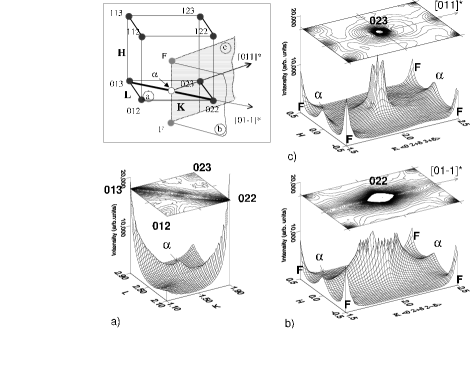
Distribution of the diffuse scattering intensity in the KL reciprocal plane defined by the (012), (013), (023) and (022) Bragg reflections at four corners is shown in Fig. 1 for PMN (at 45 K) and PMN-0.1PT (100 K). Horizontal axes (x and y) correspond to K () and L () reciprocal lattice directions with intensity plotted along the vertical z axis on the linear scale. In addition, contour plots are displayed above the corresponding surface plots in Fig. 1 for better visualization. Only the diffuse scattering tails measured (r.l.u.) away from the Bragg peak maxima are visible in Fig. 1. Centers of the Bragg peaks are outside the plot boundaries because their intensities are more than times greater.
Two pronounced diffuse scattering ridges connecting (013) and (022) Bragg peaks can be readily identified on both plots in Fig. 1. Fig. 1(a) also demonstrates the existence of a very weak and diffuse 1/2(035) spot located half way between (013) and (022) Bragg peaks in PMN at 45 K. The FWHM of this peak along direction corresponds to 0.1 (r.l.u.), which is more than 100 times larger than the width of the fundamental Bragg peaks. Due to the inverse relationship between the reflection width and the correlation radius in the real space defined by the well-known Scherrer relationship Warren (1969), the corresponding length scale of the spot is about 30 , which is comparable in size with previously mentioned CND (50 ). Moreover, there is no clear evidence for such a peak for data in Fig. 1(b), obtained with identical experimental setup. Therefore, absence of the 1/2(035) spot in Fig. 1(b) together with the FWHM argument excludes the origin of the superlattice peak in PMN from diffraction of the contaminating x-ray harmonic.
Previous reports of the F and spots measured with x-rays were presented from the linear 1D reciprocal scans Vakhrushev et al. (1996); Zhang et al. (1996); Gosula et al. (2000). Also, transmission electron microscopy (TEM) images (2D reciprocal maps) clearly show diffuse ridges similar to the one in Fig. 1, which intersect locations of the 1/2(hk0) spots Hilton et al. (1990); Miao et al. (2002), e. i. spots in our notation. Therefore, if these diffuse scattering ridges are 1D linear features in the reciprocal space, any scan that intersects their line of direction will produce a peak cross section regardless of existence of the 1/2(035) peak in Fig. 1a. This means that if the spot is a real peak produced by 3D correlations, it must exhibit peak cross section in any direction regardless of the direction of the reciprocal scan.

In order to prove this point, we measured diffuse scattering intensity in three mutually perpendicular reciprocal planes that contain 1/2(035) spot from Fig. 1(a). Experimental data is presented in Fig. 2 for corresponding , and planes. The locations of these three planes relative to the reciprocal unit cell can be identified from the sketch depicted on the top left corner of the figure. Cube corners marked with black circles correspond to fundamental cubic perovskite Bragg reflections. F spots and spots can be identified on body-centered (grey circles) and face-centered (white circle) cubic positions, respectively. Note that only one 1/2(035) spot is shown to reduce clutter. Fig. 2(b) and (c) also indicate the absence of edge-centered peaks, called spots in related variable order (PIN) relaxor Nomura et al. (1997), which once again proves the absence of any detectable contamination in the incident x-ray beam. Data in Fig. 2(a) are the same data shown in Fig. 1(a), while data in Fig. 2(b) and (c) were taken at 160 K and plotted on the same vertical scale for direct intensity comparison. Both planes and contain direction, which is drawn in the sketch with a thick line connecting (013) and (022) Bragg peaks. Observation of the 1/2(035) spot along any reciprocal direction in these planes unambiguously proves its 3D origin. It is important to note from Fig. 2(b) and (c), that less than 50 % of the total peak cross section at H=0 along the H axis ( e. i. [100]* direction), corresponds to the actual spot superlattice peak, assuming that diffuse ridge is from different origins. In fact, the first report of the spot with synchrotron x-rays was also presented using linear [100]* reciprocal scan, which may be contaminated by the * diffuse ridge Vakhrushev et al. (1996).
Moreover, if the cross section of the diffuse ridge had not been accounted for, the presence of the spots would have been concluded for PMN-0.1PT at 100 K, which is in fact not the case according to Fig. 1(b). Our measurements in a wide 15-800 K temperature interval have shown that peak cross sections of the ridges near zone boundary do not change even above the Burn’s temperature Tkachuk and Chen (2002). Since diffuse ridges in the form of 1D linear features are always present, observation of the spots above 220 K by other workers can be explained by measuring primarily diffuse ridge cross sections instead of actual spots Miao et al. (2002); Hilton et al. (1990); Vakhrushev et al. (1996).
On the other hand, it is well known that diffuse scattering in PMN at 0.1 (r.l.u.) from the Brillouin zone centers exhibits strong temperature dependence Vakhrushev et al. (1996); Hirota et al. (2002); You and Zhang (1997). In contrast, temperature independent diffuse scattering at zone boundaries (q=0.5 r.l.u.) suggests that diffuse scattering observed in different parts of the reciprocal space comes from different origins. For example, temperature independent * diffuse scattering ridges were reported to exist in related Pb(Sc1/2Nb1/2)O3 (PSN) relaxor Malibert et al. (1997). The origin of the ridges has been attributed to static or dynamic displacements in planes without (or with weak) correlation between the planes along directions. Observation of the spots in PSN with synchrotron x-rays was explained by Takesue et al. due to existence of the linear anti-ferroelectric chains Takesue et al. (1999). However, displacement correlation lengths were calculated from the widths of the peaks measured at the positions of the spots by three * scans without taking into account cross sections of the overlapping diffuse ridges. From now on, if not otherwise mentioned, all the quantitative spot analyses have been performed along the direction of the * diffuse ridges.
Glazer studied the origins of the different superlattice reflections in perovskites Glazer (1975). According to his proposed classification scheme, the origin of the spots can be attributed to correlated in-phase oxygen octahedra rotations about the axis defined by even index in the 1/2(hkl) notation Glazer (1975). In this case, the presence of the 1/2(035) spot in Fig. 2 would correspond to unit cell doubling along directions, which should lead to local tetragonal distortions along the rotation axis . Note that correlation length of these in-phase rotations must be 30 Å according to the width of the spot.
It has been also shown that Pb2+ ions are significantly displaced by about 0.3 from their equilibrium positions according to pair distribution function (PDF) measurements in PMN Egami et al. (1998). However, PDF measurements cannot answer the question along which particular directions these Pb ions are displaced, due to local probe nature of this experimental technique. On the other hand, Bragg peak structure factor refinements Bonneau et al. (1991); de Mathan et al. (1991); Chernyshev and Zhukov (1998) and analysis of the polarization vectors from neutron diffuse scattering Vakhrushev et al. (1995); Hirota et al. (2002) in PMN have inferred existence of nonuniform parallel Pb displacements preferential along or rhombohedral polar directions at low temperatures. However, in order to contribute to the structure factor of the spots, some fraction of the Pb atoms must be also short-range correlated in directions in an anti-parallel fashion, required for unit cell doubling. Indeed, our structure factor calculations, which will be discussed later in this paper, prove direct involvement of the Pb displacements in production of the 1/2(hk0) superlattice reflections.
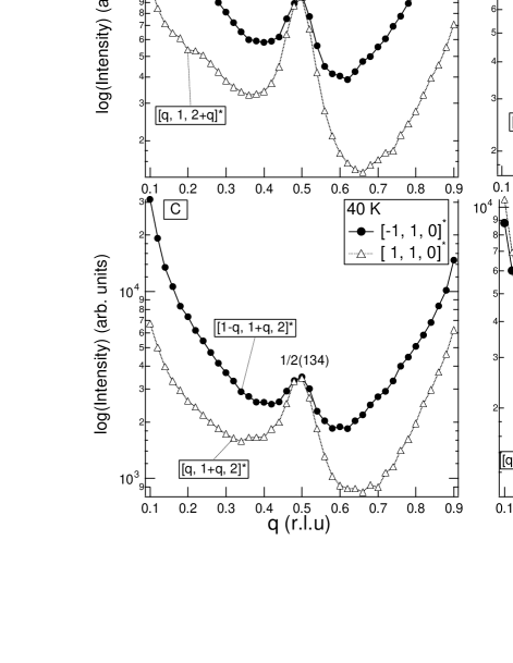
Since average PMN structure is cubic at all temperatures, displacements that give rise to spots must be correlated on the nanometer scale along all symmetry equivalent cubic directions, which would lead to appearance of the spots on every face-centered position in the reciprocal unit cell. Indeed, we found spots on all six reciprocal cubic faces shown Fig. 2 sketch below in PMN. Corresponding linear scans along the direction of the diffuse scattering ridge () and scans perpendicular to this direction () are shown in Fig. 3. Scans along are plotted using solid circles and the scans along directions are plotted with empty triangles. Peaks on the solid circle curves at q=0.5 are the actual spots ”sitting” on top of the large background created by the diffuse ridges. Peaks on the empty triangle curves are produced by the contributions from both spots and the cross sections of the diffuse ridges. These data clearly demonstrate that large errors would occur if integrated intensities of the spots are extracted from the empty triangle scans rather than from the solid circle ones. The relative intensities of the * ridges are different and appear to be correlated with the structure factors of the Bragg peaks that they connect. For example, 1/2(145) and 1/2(136) spots in Fig. 3(e) and (f), which are located between relatively weak Bragg peaks, are the least affected by the anisotropy of the diffuse scattering background.
Extracted FWHM values for several spots, including solid circle scans in Fig. 3 , are shown in Fig. 4. The average size of the fluctuations responsible for the spots corresponds to from Scherrer equation. Notice that FWHM is the same, within experimental errors, for all the reflections in Fig. 4 independent of the reflection’s distance from the origin of the reciprocal space. This indicates that the width is predominantly defined by the size of the nanoregions rather than by strain effect, which typically increases the width of the diffraction peaks located further away from the center of the reciprocal space.
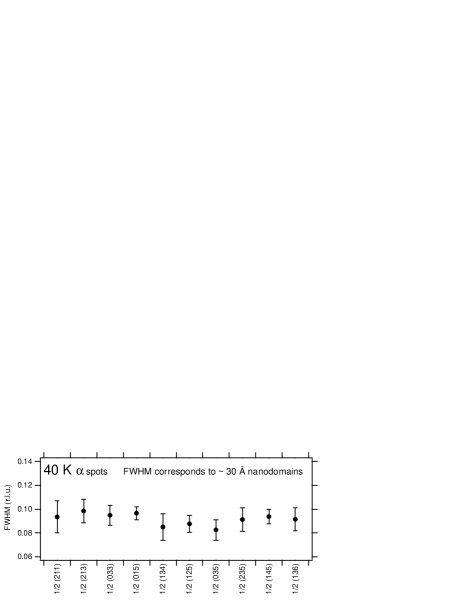
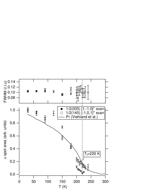
Figure 5 presents temperature dependence of the integrated intensity and FWHM values of the spots measured along * diffuse ridge without electric field. Normalized remanent polarization Pr digitized from Ref. Viehland et al. (1992) is also shown on the same graph as a guide to the eye. Remarkably, significant reduction in the intensity of the spots on heating occurs near the phenomenological freezing phase transition Tf, which is not accompanied by any kind of Bragg peak splitting de Mathan et al. (1991); Bonneau et al. (1991) in the absence of applied electric field Calvarin et al. (1995); Vakhrushev et al. (1997). This does not contradict average cubic structure, since FWHM0.1 (r.l.u.) of the spots corresponds to 30 Å correlation length. It also appears to be temperature independent below Tf within experimental errors.
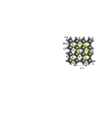
Integrated intensity of the diffraction peaks is proportional to their structure factor F (), which can be directly calculated if the positions of all atoms in the unit cell are known Warren (1969). According to earlier discussion, integrated intensities of the spots must be extracted from the scans along the diffuse ridge directions (e. g. solid circles in Fig. 3). In order to calculate structure factors of the spots, we considered a doubled unit cell (). Figure 6 shows a proposed displacement pattern where anti-parallel Pb displacements double unit cell along direction. In-phase oxygen octahedra rotations along the axis (perpendicular to the plane of the graph) are also shown as another possible contribution to the structure factor of the spots. Corners of the the octahedra are oxygen atoms, Nb/Mg are located inside of the oxygen ocathedrons and Pb atoms, displaced from the equilibrium sites, are positioned interstitially in the oxygen octahedra network.
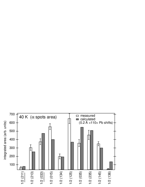
Measured at 40 K, integrated intensities of the spots are represented as white bars in Fig. 7 after performing standard absorption and Lorentz factor data corrections Warren (1969). Structure factor modeling without Pb displacements (only pure oxygen octahedra rotations) shows that spots with identical odd indices are forbidden Glazer (1975); Tkachuk (2002). However, reflections, such as 1/2(211) and 1/2(033), were experimentally observed and their corresponding integrated intensities are nonzero according to Fig. 7 . The results of the least squares fit with only two variable parameters are presented as gray bars. All reflections were fitted at once. One of the fitting parameters was a magnitude of the Pb displacements , and another was common for all peaks intensity scaling factor. Debye-Waller factors were taken from the literature Vakhrushev et al. (1995); Chernyshev and Zhukov (1998); Lebedinskaya et al. (2001). Structure factor calculations showed, that pattern in Fig. 6 would only contribute to the spots, which have even third Miller index (), such as 1/2(134) and 1/2(136) in Fig. 3. Similar patterns with Pb displacements having 30 Å correlation length along other equivalent directions will contribute to reflections with or even indices, accordingly.
The actual displacement pattern may be more complicated than the one presented in Figure 6, which could contribute to the differences between observed and calculated structure factor results for some reflections in Fig. 7. Inclusion of Nb displacements or in-phase oxygen octahedra rotations with angles up to 10∘ only marginally improved the fit. Neutron measurements, which are more sensitive to oxygen, are clearly needed in order to better understand the role of oxygen octahedra rotations. What is important is that oxygen octahedra alone cannot explain spot structure factor without Pb displacements. Contribution of Pb displacements to the spots is consistent with differential anomalous factor scattering (DAFS) measurements near Pb LIII absorption edge Tkachuk (2002). On the contrary, we were not able to find any evidence for Nb contribution from the DAFS measurement near Nb edge Tkachuk (2002).
Interesting conclusions can be made from a comparison of the and F spots in PMN with the superlattice reflections found in PMN-0.06PT single crystal Tkachuk et al. (2001). According to our measurements, the sizes of the nanoregions that give rise to the spots in PMN-0.06PT and pure PMN are identical within experimental errors, i. e. 30 . At the same time, the size of the CND regions in PMN-0.06PT, obtained from the width of the F spots, is only 25 , which is half the size of CND regions in PMN. These results together with observed strong temperature dependence of the spots Tkachuk et al. (2001), indicate that their origins must be different and unrelated to the CND regions where short-range chemical ordering is quenched and therefore temperature invariant Akbas and Davies (2000).
We have shown that spots are distinct 3D peaks, which means that producing them nanoregions scatter radiation coherently. If they scattered radiation incoherently, we would have observed ”powder rings” in the reciprocal space, as in the case of powder diffraction Warren (1969). Therefore, intensity of the spots is determined either by the total number of these nanodomains or by magnitude of the atomic displacements. In a separate experiment we observed expected Calvarin et al. (1995); Vakhrushev et al. (1997) rhombohedral splitting of the Bragg peaks in PMN(111) Tkachuk (2002) under electric field 1.8 kV/cm. However, we did not register any changes in either FWHM or intensity of the spots in both field cooled and zero field cooled regimes below Tf, in contrast to PNRs Dkhil and Kiat (2001). This fact indicates that changes in the average macrostructure have no effect on either size or number of the nanoregions that give rise to the spots.
It is not possible to determine how many different directions are operative within a single nanodomain. Important fact is that this type of correlated anti-parallel Pb distortions is expected to compete with parallel ferroelectric Pb displacements believed to be present in PNRs de Mathan et al. (1991); Vakhrushev et al. (1995); Hirota et al. (2002). These new nanodomains, which give rise to spots, fit the description of anti-polar nanoregions (AFR) due to anti-ferroelectric like displacements of the Pb atoms from one unit cell to another along equivalent directions. Absence of spots in PMN-0.1PT can be due to much smaller total number of anti-ferroelectric nanodomains when compared to pure PMN or PMN-0.6PT, which would be responsible for peaks not resolvable even with synchrotron radiation. Alternatively, relaxor behavior in PMN-0.1PT can be explained due to different competing mechanism, such as local Pb displacements without any unit cell doubling Dkhil et al. (2002).
IV conclusions
Anti-ferroelectric ordering is established by correlated atomic displacements which produce dipole moments with anti-parallel arrangement throughout the crystal. Studies of anti-ferroelectric nanodomains with techniques sensitive to electric dipoles are challenging, since the net polarization for each nanoregion is zero.
From diffraction point of view, each type of fluctuations contributes intensity to the different parts of the reciprocal space. Diffuse scattering from ferroelectric fluctuations (PNR) is mainly concentrated near fundamental Bragg reflections while anti-ferroelectric fluctuations produce diffuse superlattice reflections ( spots in the case of PMN) at the Brillouin zone boundaries as a result of the unit cell doubling. Structural differences between anti-ferroelectric nanoregions and cubic host lattice were studied in this work based on temperature dependence and structure factor modeling of spots. These peaks are extremely weak, however utilization of third generation synchrotron x-ray sources allowed us to study their temperature dependence after separation from anisotropic linear diffuse ridges, which become temperature independent for q0.1 (r.l.u.) away from the Brillouin zone centers Tkachuk and Chen (2002)
Correlation length, obtained from the width of the spots, is only 30 Å, which defines the average size of producing these peaks nanodomains. These nanodomains are formed by short-range correlated anti-parallel Pb displacements along equivalent directions with a magnitude of 0.2 Å based upon the structure factor calculations. Fluctuations created by these locally correlated displacements are different from chemical nanodomains (CND) and ferroelectric polar nanoregions (PNR); they constitute a new type of fluctuations with anti-ferroelectric type displacement ordering (AFR) based on anti-parallel nature of the Pb displacements.
Freezing phase transition has been identified in PMN near T220 K from the temperature dependence of the integrated intensity of the spots without application of the external electric field. Significant enhancement in the intensity of the spots below Tf we attribute to increase in a total number of AFRs, which average size (30 Å) remains constant down to the lowest measured temperature of 10 K. Nothing can be said about dynamics of these fluctuations from our studies, since interaction time between electrons and x-rays during the scattering process is 10-15 sec. Similar increase in the total number of ferroelectric fluctuations (PNR) near was reported from recent macroscopic polarization measurements under applied DC electric field Dkhil and Kiat (2001). Competition between randomly occurring anti-ferroelectric and ferroelectric fluctuations may be responsible for the relaxor behavior in PMN.
V acknowledgments
We would like to thank: Dr. Zschack from the UNICAT ID-33 beamline at the APS, ANL; Dr. Ehrich from the MATRIX X-18A beamline at the NSLS, BNL; Dr. Vigliante, Dr. Wohner, Dr.Kasper and Prof. Dosch from Max Plank Institute, Stuttgart, Germany for technical assistance during the experiments and enlightening discussions.
Authors also would like to thank Dr. Colla and Prof. Feigelson for providing good quality PMN single crystals and stimulating discussions. Special thanks to Dr. Vakhrushev for a very fruitful discussion regarding data interpretation in the final stage of this manuscript preparation.
This research is based upon work supported by the U.S. Department of energy, Division of Materials Sciences under award No. DEFG02-96ER45439 and by the state of Illinois IBHE HECA NWU A207 grant, though the Frederick Seitz Materials Research Laboratory at the University of Illinois at Urbana-Champaign.
National Synchrotron Light Source (NSLS) is supported by the U.S. Departrment of Energy under Contract No. DE-AC02-76CH00016. Use of the Advanced Photon Source was supported by the U.S. Department of Energy, Basic Energy Sciences, Office of Science, under Contract No. W-31-109-Eng-38.
References
- Bonneau et al. (1991) P. Bonneau, P. Garnier, G. Calvarin, E. Husson, J. R. Gavarii, A. W. Hewat, and A. Morell, J. Solid State Chem. 91, 350 (1991).
- de Mathan et al. (1991) N. de Mathan, E. Husson, G. Calvarin, J. R. Gavarii, A. W. Hewat, and A. Morell, J. Phys.: Condens. Matter 3, 8159 (1991).
- Cross (1994) L. E. Cross, Ferroelectrics 151, 305 (1994).
- Husson et al. (1988) E. Husson, M. Chubb, and A. Morell, Mat. Res. Bull. 23, 357 (1988).
- Hilton et al. (1990) A. D. Hilton, D. J. Barber, C. A. Randall, and T. R. Shrout, J. Mater. Sci. 25, 3461 (1990).
- Akbas and Davies (2000) M. A. Akbas and P. K. Davies, J. Am. Ceram. Soc 83, 119 (2000).
- Egami et al. (1997) T. Egami, S. Teslic, W. Dmowski, D. Viehland, and S. Vakhrushev, Ferroelectrics 199, 103 (1997).
- Egami et al. (1998) T. Egami, W. Dmowski, S. Teslic, P. K. Davies, I. W. Chen, and H. Chen, Ferroelectrics 206-207, 231 (1998).
- Burns and Dacol (1983) G. Burns and F. H. Dacol, Solid State Commun. 48, 853 (1983).
- Chernyshev and Zhukov (1998) V. V. Chernyshev and S. G. Zhukov, Crystallography Reports 43, 171 (1998).
- Vakhrushev et al. (1989) S. B. Vakhrushev, B. E. Kvyatkovsky, A. A. Naberezhnov, N. M. Okuneva, and B. P. Toperverg, Ferroelectrics 90, 173 (1989).
- Blinc et al. (2000) R. Blinc, J. Dolinsek, A. Gregorovic, B. Zalar, C. Filipic, Z. Kutnjak, and A. Levstik, J. Phys. Chem. Solids 61, 177 (2000).
- Lebedinskaya et al. (2001) A. R. Lebedinskaya, M. F. Kupriyanov, and R. Skulski, Mater. Sci. Eng. B-Solid State Mater. Adv. Technol 83, 119 (2001).
- Miao et al. (2002) S. Miao, J. Zhu, X. W. Zhang, and Z. Y. Cheng, Phys. Rev. B 6505, 2101 (2002).
- Dkhil et al. (2002) B. Dkhil, J. M. Kiat, G. Calvarin, G. Baldinozzi, S. B. Vakhrushev, and E. Suard, Phys. Rev. B 6502, 4104 (2002).
- Krause and Gibbon (1971) B. Krause and D. Gibbon, Z. Krist. 134, 44 (1971).
- Viehland et al. (1991) D. Viehland, J.-F. Li, S. J. Jang, L. E. Cross, and M. Wutting, Phys. Rev. B 43, 8316 (1991).
- Shrout et al. (1990) T. R. Shrout, Z. P. Chang, N. Kim, and S. Markraf, Ferroelectrics Letters 12, 63 (1990).
- Chen (2000) I.-W. Chen, J. Phys. Chem. Solids 61, 197 (2000).
- Colla et al. (1996) E. V. Colla, S. B. Vakhrushev, E. Y. Koroleva, and N. M. Okuneva, Phys. Solid State 38 (1996).
- Dorogovtsev and Yushin (1990) S. N. Dorogovtsev and N. K. Yushin, Ferroelectrics 112, 27 (1990).
- Dkhil and Kiat (2001) B. Dkhil and J. M. Kiat, J. Appl. Phys. 90, 4676 (2001).
- Shebanov et al. (1984) L. S. Shebanov, P. P. Kapostins, and J. A. Zvirgzds, Ferroelectrics 56, 53 (1984).
- Calvarin et al. (1995) G. Calvarin, E. Husson, and Z. G. Ye, Ferroelectrics 165, 349 (1995).
- Vakhrushev et al. (1997) S. B. Vakhrushev, J.-M. Kiat, and B. Dkhil, Solid State Commun. 103, 477 (1997).
- Westphal et al. (1992) V. Westphal, W. Kleemann, and M. D. Glinchuk, Phys. Rev. Lett. 68, 847 (1992).
- Glazounov and Tagantsev (2000) A. E. Glazounov and A. K. Tagantsev, Phys. Rev. Lett. 85, 2192 (2000).
- Vakhrushev et al. (1995) S. B. Vakhrushev, A. A. Naberezhnov, N. M. Okuneva, and B. N. Savenko, Phys. Solid State 37, 1993 (1995).
- Vakhrushev et al. (1996) S. Vakhrushev, A. Nabereznov, S. K. Sinha, Y. P. Feng, and T. Egami, J. Phys. Chem. Solids 57, 1517 (1996).
- Zhang et al. (1996) Q. M. Zhang, H. You, M. L. Mulvihill, and S. J. Jang, Solid State Commun. 97, 693 (1996).
- Gehring et al. (2001) P. M. Gehring, S. Wakimoto, Z. G. Ye, and G. Shirane, Phys. Rev. Lett. 8727, 7601 (2001).
- Hirota et al. (2002) K. Hirota, Z.-G. Ye, S. Wakimoto, P. M. Gehring, and G. Shirane, Phys. Rev. B 65, 104105 (2002).
- Wakimoto et al. (2002) S. Wakimoto, C. Stock, R. J. Birgeneau, Z.-G. Ye, W. Chen, W. J. L. Buyers, P. Gehring, and G. Shirane, Phys. Rev. B 65, 172105 (2002).
- You and Zhang (1997) H. You and Q. M. Zhang, Phys. Rev. Lett. 79, 3950 (1997).
- You (2000) H. You, J. Phys. Chem. Solids 61, 215 (2000).
- Naberezhnov et al. (1999) A. Naberezhnov, S. Vakhrushev, B. Dorner, D. Strauch, and H. Moudden, Eur. Phys. J. B 11, 13 (1999).
- Gosula et al. (2000) V. Gosula, A. Tkachuk, K. Chung, and H. Chen, J. of Phys. Chem. of Solids 61, 221 (2000).
- Nomura et al. (1997) K. Nomura, N. Yasuda, H. Ohwa, and H. Terauchi, J. Phys. Soc. Jpn. 66, 1856 (1997).
- Tkachuk et al. (2001) A. Tkachuk, P. Zschack, E. Colla, and H. Chen, AIP. American Institute of Physics Conference Proceedings, no 582, 45 (2001).
- Tkachuk and Chen (2002) A. Tkachuk and H. Chen, cond-mat/0303012 (will appear in ”Fundamental Physics of Ferroelectrics 2003”) (2002).
- Colla et al. (1998) E. V. Colla, N. K. Yushin, and D. Viehland, J. Appl. Phys. 83, 3298 (1998).
- Lee et al. (1999) S. G. Lee, R. G. Monteiro, R. S. Feigelson, H. S. Lee, M. Lee, and S. E. Park, Appl. Phys. Lett. 74, 1030 (1999).
- Warren (1969) B. E. Warren, X-ray Diffraction (Dover Publications Inc., New York, 1969).
- Malibert et al. (1997) C. Malibert, B. Dkhil, J.-M. Kiat, D. Durand, J. F. Berar, and A. S. d. Bire, J. Phys.: Condens. Matter 9, 7485 (1997).
- Takesue et al. (1999) N. Takesue, Y. Fujii, M. Ichihara, and H. Chen, Phys. Rev. Lett. 82, 3709 (1999).
- Glazer (1975) A. M. Glazer, Acta Cryst. A 31, 756 (1975).
- Viehland et al. (1992) D. Viehland, S. J. Jang, L. E. Cross, and M. Wutting, Phys. Rev. B 46, 8003 (1992).
- Tkachuk (2002) A. Tkachuk, Ph.D. thesis, University of Illinois at Urbana-Champaign (2002).