Colloidal interactions in two dimensional nematics
Abstract
The interaction between two disks immersed in a 2D nematic is investigated (i) analitically using the tensor order parameter formalism for the nematic configuration around isolated disks and (ii) numerically using finite element methods with adaptive meshing to minimize the corresponding Landau-de Gennes free energy. For strong homeotropic anchoring, each disk generates a pair of defects with one-half topological charge responsible for the 2D quadrupolar interaction between the disks at large distances. At short distance, the position of the defects may change, leading to unexpected complex interactions with the quadrupolar repulsive interactions becoming attractive. This short range attraction in all directions is still anisotropic. As the distance between the disks decreases their preferred relative orientation with respect to the far-field nematic director changes from oblique to perpendicular.
PACS numbers: 77.84.Nh Liquids, emulsions, and suspensions; liquid crystals - 61.30.cz Theory and models of liquid crystal structure - 61.30.Jf Defects in liquid crystals.
I Introduction
In the last few years, there has been considerable theoretical and experimental interest in colloidal systems with anisotropic host fluids [1].
Since the temperature changes the anisotropic properties of the host fluid, the dispersed particles exhibit a rich variety of collective behaviors, leading to unexpected phase diagrams [2]. Depending on the details of the system, chain-like [3, 4], crystal [5] or cellular [6] structures have been observed.
In the case of nematic hosts in three dimensions (3D), the colloidal interactions result from the competition between the anchoring properties of the spherical colloidal surfaces favoring e.g., radial (homeotropic) nematic orientation (anchoring) and the bulk elasticity that favors a uniform nematic. For sufficiently strong homeotropic anchoring , the spherical colloids may induce topological defects or singularities in the nematic director field. If the size of the colloidal particle is large when compared to the nematic correlation length , a hyperbolic point defect appears at a certain distance from the particle (satellite dipolar configuration [7, 8, 9, 10]). For smaller particles, however, a ring disclination around the equatorial plane of the sphere may have a lower energy (saturn-ring quadrupolar configuration [11]). Finally, if is smaller than the typical nematic elastic constant , the director field varies smoothly and there are no defects (surface-ring quadrupolar configuration [12]). Depending on the symmetry of the distortion [13], the dominant long range interactions are dipolar [14] or quadrupolar [15, 16]. The short range interactions are more difficult to predict, as nonlinear terms in the elastic free energy come into play. Experimental evidence from a system where silicon oil droplets were dispersed in a nematic host [17] reveals that when the nematic configuration around each droplet has dipolar symmetry, the attractive long range interaction between aligned droplets becomes strongly repulsive at short distances. A nematic topological defect appears between the particles and prevents their collapse. By contrast, when the long range distortion exhibits quadrupolar symmetry no such defects appear and the oil droplets coalesce.
2D colloidal systems were also investigated recently and similar qualitative features were observed. In these systems the interactions between the dispersed particles are also mediated by the elastic distorsions of the anisotropic host. However, for 2D nematic hosts and homeotropic anchoring conditions, only quadrupolar configurations are stable [18]. Dipolar configurations may be found in 2D smectic C films [19], a system that is similar to a 2D nematic, but where the director does not exhibit mirror symmetry, thus excluding configurations with half integer topological charges. In this case, Pettey et al. [20] obtained analytic expressions for the free energy of a system of multiple disk-defect pairs, valid in the linear regime where the particles are sufficiently far apart. We investigated the short range interactions in this system by using a numerical method capable of describing the nematic orientation profiles induced by a small number of colloids with arbitrary shape in 2D [21]. Numerical investigations of this type are faced with a problem due to the very different length scales characterizing the colloids and the topological defects. We have solved it [21], by using finite elements with adaptive meshing to minimize the Frank free energy and obtained very accurate interaction energies between disks at arbitrary separations. We have found a strong repulsion at short range followed by the expected long range dipolar interaction with a pronounced minimum at an intermediate distance. The equilibrium director field configuration exhibits a topological defect at the mid-point between the disks.
In this article, we use similar numerical methods [21] to minimize the Landau-de Gennes free energy of two circular disks in a 2D nematic. The great advantage of this model is that no special treatment of the topological defects is required, by contrast with the Frank elastic free energy description, where the defects appear as singularities of the director field . In the next section, we describe the nematic free energy based on the tensor order parameter formalism. Then, we generalize the analytical results of Pettey et al. [20] to nematic configurations with half integer topological defects and obtain analytic expressions for the free energy of the quadrupolar nematic distortion for a single disk and the long range quadrupolar interaction between disks. Finally, we present the results of extensive numerical calculations for the interaction between disks at arbitrary separations.
II The Landau-de Gennes free energy
In the tensor order parameter formalism the 2D nematic order is represented by the (tilt) angle of the director field , that describes the mean orientation of the molecules, and the orientational order parameter , that measures the degree of alignment of the molecules with respect to the mean orientation. In the isotropic phase, where the molecules point in every direction, . By contrast, in the nematic phase the molecules are preferentially aligned and the orientational order parameter takes a well defined equilibrium value that depends on the temperature.
We define a 2D symmetric traceless tensor field, from the tilt angle and the orientational order parameter ,
| (1) |
that is invariant under the nematic symmetry operations and .
The Landau-de Gennes free energy may be understood as a Taylor expansion in terms of the tensor order parameter (the bulk free energy) and its derivatives (the elastic free energy) [22]:
| (2) |
where the summation over repeated indices is implied. The integration is over the 2D space occupied by the nematic . Only terms with the nematic symmetry are allowed in the free energy expansion. In addition, stability requires that the total free energy is bounded from below. In the nematic and are positive constants, defining the equilibrium value of the orientational order parameter . For simplicity, we adopted the one-constant approximation for the elastic free energy. In the general 2D case two elastic terms – corresponding to different invariant derivatives of the tensor order parameter – have to be included in the expansion. The elastic constant is related to the Frank elastic constant through . The total free energy can be written as a functional of the tilt angle and the orientational order parameter :
| (3) |
Let be a typical length of the system, e.g. the radius of the colloidal particles. If , the energy associated with the variation of the tilt angle is much smaller than the energy associated with the orientational order parameter. In this case we may set everywhere in the nematic and the free energy simplifies to
| (4) |
which is the one-constant elastic Frank free energy.
For strong distortions, however, topological defects may appear. In this case the director field becomes singular and within a small region around the defect the orientational order parameter vanishes and the contribution of the first three terms in Eq.(3) has to be taken into account. This energy – the core energy of the defect – arises from a small region of size , and may be estimated by a boundary layer analysis [23].
Let us consider a topological defect of charge placed at the center of the 2D space. In polar coordinates , the defect may be described by , asymptotically valid in the core region , far from any other boundaries. The orientational order parameter, constant outside the core region, decreases rapidly to inside the core in order to regularize the nematic free energy. A simple description of this behavior of is given by the ansatz
| (5) |
By substituting this expression into the free energy (3) we obtain the simple result
| (6) |
where and is the size of the system. Differentiation with respect to yields , where is the nematic correlation length. If is much smaller than the other characteristic lengths of the system, we can use the Frank elastic free energy (4) to obtain the director configuration in systems with topological defects. The Frank elastic free energy, however, is defined outside the core region only. The total free energy can be computed by additing to it the core energy of each defect
| (7) |
III Isolated disk
Fukuda and Yokoyama [18] studied the distortion of a 2D nematic around an isolated disk, with homeotropic anchoring, by minimizing the Landau-de Gennes free energy (2) using numerical methods with adaptive grids. They have shown that a director configuration with a dipolar defect (topological charge ) is unstable, and changes into a configuration with a pair of defects with topological charge that are located symmetrically around the particle.
The energy of this quadrupolar configuration may be calculated analitically and compared with the energy of the dipolar case, obtained by Pettey et. al. [20] for 2D smectic-C films.
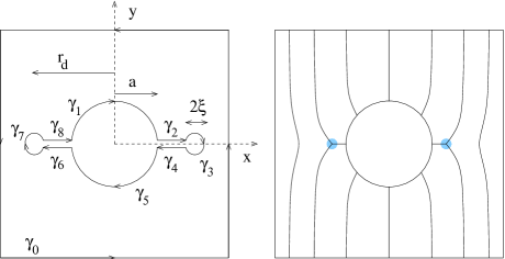
Consider the disk at the center of the reference frame , or in polar coordinates, where is defined counterclockwise, starting from the -axis, in the range (see Fig.1). At the outer boundary, for large , the nematic is uniform with . Homeotropic boundary conditions apply at the disk’s boundary, i.e., on the upper contour and on the lower one. Minimization of the Frank elastic free energy (4) yields Laplace’s equation , everywhere (in the nematic) except within the defects.
An image solution with two half integer topological charges located symmetrically at a distance from the center of the disk, satisfying the homeotropic boundary conditions at the disk’s contour and a uniform director at infinity, is given by
| (8) |
where is the position of a virtual half integer topological defect inside the disk. The field
| (9) |
describes a topological defect of charge located at and satisfies Laplace’s equation everywhere except at .
The elastic Frank free energy can be calculated using Green’s Theorem:
| (10) |
where is the boundary of the 2D nematic domain, is an oriented contour element, and . If the tilt angle satisfies Laplace’s equation, the second term on the right hand side of (10) vanishes, and the free energy becomes
| (11) |
Close to the outer boundary, for , the director is nearly uniform and the contribution of the integral over this contour may be neglected. The contribution of the integral over the upper disk’s contour is calculated by taking with , yielding
| (12) |
By symmetry the integral over the lower disk’s contour is identical.
Now consider the integrals over the straight lines along the -axis from the disk to the defects. On and , the tilt angle is zero and there is no contribution to the free energy. On (and ), and a simple calculation yields
| (13) | |||||
| (14) |
in the limit . If we may neglect the contributions from the circular contours around the defects. Finally, the Frank elastic free energy is given by
| (15) |
Minimizing with respect to yields , as obtained by Fukuda and Yokoyama [18] using a simple force balance argument. The total free energy for this quadrupolar configuration is obtained by adding the core energy of the defects , and using the appropriate core’s size .
The Frank elastic free energy for a dipolar configuration, with a topological defect of charge , with the preferred position at was calculated by Pettey et. al. [20]:
| (16) |
yielding the equilibrium position . The core energy of the defect is now , and the core’s size is .
The difference between the free energy of these configurations, when the core energies of the defects are taken into account, is a function of the correlation length :
| (17) |
For , the difference is positive, and thus the quadrupolar configuration has the lowest free energy.
This result contrasts with that for spherical colloidal particles in 3D nematic liquid crystals. In the latter case, the dipolar configuration has a punctual defect (with zero core energy). The quadrupolar configuration exhibits a disclination ring, and its elastic free energy depends logarithmically on the ratio between the correlation length and the particle’s radius. For small particles, the nematic distortion is of the quadrupolar type. As we increase the ratio , the energy of the quadrupolar configuration increases, and eventually exceeds that of the dipolar configuration. This crossover occurs at , that corresponds to particles with radii of the order of m.
IV Long range interaction
If the separation between particles is large, the nematic distortion will be approximately the sum of the isolated quadrupolar solutions, , with an interaction energy
| (18) | |||||
| (19) |
where the subscripts refer to the different disks (see Fig.2).

Consider the integral over the contour around the second disk. We use the same notation as for isolated disks and neglect the contributions from the circular contours around the defects. To calculate the contribution from the upper circular contour around disk 2 we write . On this contour , and can be expanded as a power series in yielding
| (20) | |||||
| (21) | |||||
| (22) |
When the contribution from the lower circular contour around the disk is added, some of the terms in (22) cancel. After integration, the sum of these two contributions gives
| (23) |
The integrals over the straight lines can be computed in a similar manner. On and the tilt angle , and there is no contribution to the free energy. On (or ), and may be expanded as a power series in . The result is
| (24) |
The derivative is obtained from the quadrupolar expression
| (25) |
valid for large . Finally, adding the symmetric contribution from the contour , the total interaction energy becomes
| (26) |
The effective interaction between disks decays as and is strongly anisotropic: repulsive if the particles are aligned horizontally or vertically ( or , respectively), and attractive for intermediate oblique orientations (the preferred orientation is ).
V Short range interaction
At small disk separations, the nematic deformation is no longer the sum of the isolated quadrupolar solutions (26).
The interaction between two circular disks was studied numerically, using finite elements with adaptive meshes to minimize the total nematic free energy at a given separation. A first triangulation respecting the predefined physical geometry (disks separation and orientation) is constructed [24]. The triangulation space corresponds to the domain of integration of the free energy. It is delimited by the disks’ boundaries and an outer boundary at infinity, in practice a large distance from the disks, of the order of . Although analytically simpler, the Frank free energy (4) is plagued with divergences of at the defects, and thus it is not the most adequate for numerical computations. For this reason, we used the Landau-de Gennes free energy (2) for a 2D nematic. The functions and are set at all vertices of the mesh and are linearly interpolated within each triangle. Using standard numerical procedures the elastic free energy is minimized under the constraints imposed by the boundary conditions, i.e., homeotropic strong anchoring at the disks perimeter and constant alignment at the outer boundary. Finally, to overcome the differences in length scales set by the disks and the defects, of up to 2 orders of magnitude (we chose ), new adapted meshes are generated iteratively from the result of the previous minimization. The new local triangle sizes are related with the variations of the previous solution. If the variations are strong, finer meshes are required in order to guarantee an almost constant numerical weight of each minimization variable [21]. The final meshes with variables and a minimal edge length of provided excellent accuracy, yielding free energies with a relative error of the order of .
To test the numerical accuracy of the procedure we calculated the nematic configuration for a single isolated disk, and found a solution with two half integer defects at , in very good agreement with the analytical result.

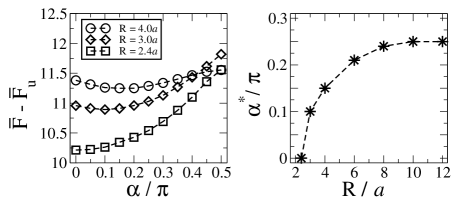
The effective interaction between two disks is plotted in Fig.3 as a function of the distance between the disks, at three different orientations (). A simple fit of these curves confirmed the quadrupolar long range decay , at large disk separations. However, for smaller separations, the free energy changes dramatically. In particular, orientations that are repulsive at large separations () become attractive at different threshold distances ( and , respectively). Also, the free energy corresponding to the parallel orientation () becomes smaller than the free energy of the long range preferred oblique orientation () at short distances.
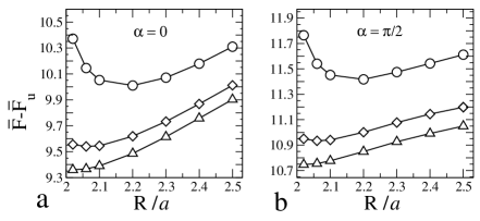
To elucidate this behavior we plotted on the left of Fig.4 the elastic free energy as a function of the orientation , at three different separations (). The minimum of each curve defines a preferred orientation , that decreases as the disks approach each other. On the right of Fig.4 we see that at very large separations, the disks have an oblique orientation (with ), that changes to a parallel orientation (with ) as their separation decreases.
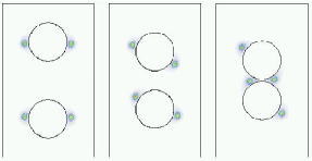
In the following figures we show the nematic order parameter for several separations, when the orientation of the disks is parallel (, Fig.5) or perpendicular (, Fig.6). The nematic order parameter varies between (grey regions) and (white). These regions around the disks correspond to the nematic defects.
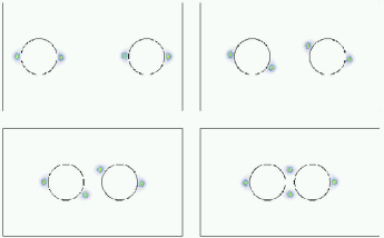
In both disk alignments, if the separation is large enough, the half integer defects around each disk stay at the same positions as in the isolated disk configuration. However, at a certain separation , exactly when the interaction becomes attractive for that orientation, the position of the defects starts to change, in order to minimize the total free energy.
Finally, we analyzed in detail the interaction between the disks for very small separations. For strong (fixed) homeotropic anchoring, we observed a repulsion when the disks are nearly at contact (for all orientations) at a separation . This repulsion may not occur if we do not impose fixed homeotropic boundary conditions at the disks. If we consider a finite anchoring strength we have to add to the free energy (2) a surface term
| (27) |
where are the values of the tensor order parameter for homeotropic alignement.
In Fig.7 we plot the total elastic free energy as a function of the distance between disks, for three different reduced anchoring strengths (). These anchoring strengths are large enough to induce defects in the nematic host. Clearly the repulsion appears at small separations for strong anchoring () and vanishes at a critical anchoring strength that lies between . In the weak anchoring regime the coalescence of the dropplets may occur.
VI Conclusions
We compared the (analytic) elastic free energies of 2D nematic configurations with one (satellite) and two (ring) defects around isolated disks with homeotropic boundary conditions, and found that the ring configuration is the stable one for realistic values of the reduced correlation length .
Using the analytic ring solution we derived the long range interaction between two disks immersed in 2D nematic hosts. We found an anisotropic interaction, that is repulsive for orientations close to perpendicular or parallel orientations and attractive for oblique alignement, with a preferred orientation at . In this limit, the interaction decays as .
Finally, the analytic results were compared with very accurate numerical calculations, valid at arbitrary separation. At small disk separations, the defects may change their positions, leading to an unexpected complex interaction with the long range repulsive orientations becoming attractive. As a result as we decrease the distance between the disks, their preferred orientation changes from oblique to parallel alignment. For sufficiently large anchoring strengths, at very short range, we found a new repulsion for all orientations, that may prevent coalescence. This repulsion vanishes for small anchoring strengths.
The equilibrium structure of inverted nematic emulsions is complex and depends sensitively on the radii of the disks, the nematic correlation length and anchoring strength. In particular short range nonlinear effects may change the interaction between disks dramatically. It is thus reasonable to assume that three body interactions may be relevant to describe the formation of the the structures observed experimentally. Finally, in order to understand the observed structures dynamical aspects may also have to be taken into account.
Acknowledgments
We acknowledge the support of the Fundação para a Ciência e Tecnologia (FCT) through a running grant (Programa Plurianual) and grants No. SFRH/BPD/1599/2000 (MT) and No. SFRH/BPD/5664/2001 (PP).
REFERENCES
- [1] H. Stark, Phys. Rep. 351, 387 (2001).
- [2] J. Yamamoto and H. Tanaka, Nature 409, 321 (2001).
- [3] P. Poulin, H. Stark, T. C. Lubensky, D. A. Weitz, Science 275, 1170 (1997)
- [4] J.-C. Loudet, P. Barois, and P. Poulin, Nature 407, 611 (2000).
- [5] V. G. Nazarenko, A. B. Nych, and B. I. Lev, Phys. Rev. Lett. 87, 075504 (2001).
- [6] V. J. Anderson, E. M. Terentjev, S. P. Meeker, J. Crain, and W. C. K. Poon, Eur. Phys. J. E 4, 11 (2001).
- [7] R. W. Ruhwandl and E. M. Terentjev, Phys. Rev. E 56, 5561 (1997).
- [8] T. C. Lubensky, D. Pettey, N. Currier, and H. Stark, Phys. Rev. E 57, 610 (1997).
- [9] H. Stark, Eur. Phys. J. B 10, 311 (1999).
- [10] D. Andrienko, G. Germano, and M. P. Allen, Phys. Rev. E 63, 041701 (2001).
- [11] Y. Gu and N. L. Abbott, Phys. Rev. Lett. 85, 4719 (2000).
- [12] O. V. Kuksenok, R. W. Ruhwandl, S. V. Shiyanovskii, and E. M. Terentjev, Phys. Rev. E 54, 5198 (1996).
- [13] B. I. Lev, S. B. Chernishuk, P. M. Tomchuk, and H. Yokoyama, Phys Rev. E 65, 021709 (2002).
- [14] P. Poulin, V. Cabuil, and D. A. Weitz, Phys. Rev. Lett. 79, 4862 (1997).
- [15] S. Ramaswamy, R. Ninyananda, V. A. Raghunathan, and J. Prost, Mol. Cryst. Liq. Cryst. 288, 175 (1996).
- [16] O. Mondain-Monval, J. C. Dedieu, T. Gulik-Krzywicki, and P. Poulin, Eur. Phys. J. B 12, 167 (1999).
- [17] J. C. Loudet and P. Poulin, Phys.Rev. Lett. 87, 165503 (2001).
- [18] J. Fukuda and H. Yokoyama, Eur. Phys. J. E 4, 389 (2001).
- [19] P. Cluzeau, P. Poulin, G. Joly, and H. T. Nguyen, Phys. Rev. E 63, 031702 (2001).
- [20] D. Pettey, T. C. Lubensky, and D. R. Link, Liquid Crystals 5, 579 (1998).
- [21] P. Patricio, M. Tasinkevych, and M. M. Telo da Gama, Eur. Phys. J. E 7, 117 (2002).
- [22] P. G. de Gennes and J. Prost, The physics of liquid crystals, 2nd ed. (Clarendon, Oxford, 1993).
- [23] P. M. Chaikin and T. C. Lubensky, Principles of condensed matter physics (Cambridge University, Cambridge, 1995).
- [24] P.-L. George and H. Borouchaki, Delaunay triangulation and meshing : application to finite elements (Hermes, Paris, 1998).