In–situ velocity imaging of ultracold atoms using slow–light.
Abstract
The optical response of a moving medium suitably driven into a slow–light propagation regime strongly depends on its velocity. This effect can be used to devise a novel scheme for imaging ultraslow velocity fields. The scheme turns out to be particularly amenable to study in–situ the dynamics of collective and topological excitations of a trapped Bose-Einstein condensate. We illustrate the advantages of using slow–light imaging specifically for sloshing oscillations and bent vortices in a stirred condensate.
pacs:
42.50.Gy, 03.75.Fi, 42.30.RxThe dynamical properties of ultracold alkali atoms and Bose-Einstein condensates are almost without exception inferred by optical methods. In most cases, these enable one to retrieve the atomic spatial density profile by using either absorption or dispersive imaging techniques. Because absorption is followed by spontaneous emission and hence heating of the sample, absorption imaging is intrinsically invasive. Dispersive imaging, on the other hand, does not involve much heating. The density profile can in this case be reconstructed non invasively by measuring the phase–shift profile of the transmitted imaging beam dark-ground-ketterle ; disp-ketterle ; polar-hulet . Yet, diffraction effects make these techniques rather inappropriate when in–situ imaging has to be performed on structures that are smaller than the wavelength of the imaging beam. For instance, a preliminary ballistic expansion to enlarge the sample size is generally required before images of a vortex in stirred Bose–Einstein condensates can actually be taken slicing ; DalibBentVort ; CornellVort .
In–situ imaging is however necessary when real–time observations of a sample dynamics need to be made and we here devise a new in-situ imaging scheme. This relies on the ultraslow propagation of the light imaging beam EIT and enables one to image ultraslow velocity fields. In a regime in which the light group velocity can be made to drop down to the m/s range SlowVg ; hemmer ; ulf-general , the optical response of a sample is found to depend so strongly on its velocity that an imaging light beam may become sensitive enough to probe very slow velocity fields of the sample. At the same time, the strong quenching of absorption EIT that is typically observed in a regime of slow–light propagation enables one to minimize the number of absorbed photons making the scheme inherently non–invasive.
We will illustrate the physics underlying slow-light imaging while discussing two examples of dynamical excitations of actual experimental interest in Bose-Einstein condensates. In one case, the center–of–mass velocity of the entire cloud is imaged by measuring the lateral shift of a narrow probe beam transversally propagating across the moving sample of atoms FresTr . In the second case, the internal velocity field of the atomic cloud is imaged by measuring the phase-shift accumulated by the probe while crossing the cloud. The spatial profile of the phase shift is shown to be proportional to the column integral of the atom current density making this second scheme well suited to the in–situ imaging of topological excitations such as vortices stringari ; Vortices . In particular, the phase shift profile obtained by using slow-light turns out to be much less affected by those diffraction effects which prevented a dispersive imaging of the vortex core. Moreover, as the probe is now sensitive to the current density rather than to the density itself, the vortex is not hidden by the surrounding stationary mass of fluid.
The dielectric function of a stationary sample of three-level atoms driven into a lambda EIT–configuration by a coupling beam of frequency and Rabi frequency has the form 111This expression refers to the usual single-atom model of the atomic polarizability EIT . Work to include the finite optical density of the medium as well as effects of quantized atomic motion is under way.:
| (1) |
where is the atomic density and the parameter is proportional to the oscillator strength of the optical transition (of wavelength ) to which the weak probe beam of frequency couples. For 87Rb atoms magnetically trapped into the sublevel of the ground state, the probe couples to an excited state which can be a hyperfine component of the excited states, while the coupling beam resonantly () couples the other hyperfine component of the ground state, denoted by , to the same excited state . For this choice of atomic levels, the state dephasing is orders of magnitude smaller than the excited state decay leading to a nearly complete suppression of probe absorption within a narrow linewidth around resonance and to a strong frequency dispersion EIT . At resonance, the refractive index and the corresponding group velocity becomes,
| (2) |
Transverse imaging.
A light ray beam propagating transversely across a slab of homogeneous medium which slowly moves with constant speed along a direction parallel to its boundaries (Fig.1 is seen to have a non–vanishing angle of incidence in the medium rest frame . The corresponding angle of refraction, obtained by using the Snell’s law in where the medium is at rest, determines the common direction of phase and group velocity in . In the laboratory frame , however, phase and group velocities are no longer parallel: by using the fact that group velocities add like particle velocities Jackson the group velocity in is found to be directed at an angle
| (3) |
with respect to the -direction. Appreciable bending of the ray beam may take place for group velocities not much larger than . This is seen to depend on the medium dispersion through the light group velocity. Physically it arises from the motion of the sample which acts as an effective transverse Fresnel drag onto the beam of light that is then bent into the direction of motion FresTr . Because the lateral shift subsequent to the deflection of the ray beam inside the medium is directly proportional to the velocity , the drag effect can be reversibly exploited to image the sample velocity.
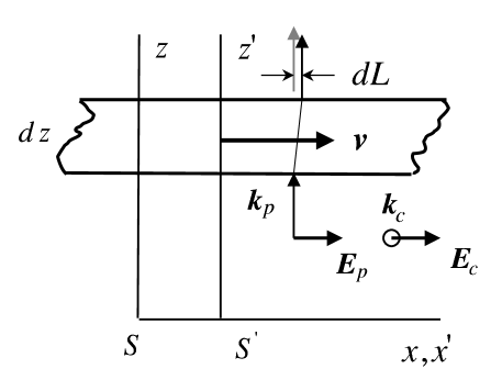
The recent observation of ultraslow group velocities in cold SlowVg alkali atomic gases suggests that substantial deflections may be observed in such media when undergoing collective motion at typical speeds of the order of several recoil velocities stringari . Consider then a well focused probe beam propagating along through an atomic layer of thickness transversally moving with velocity in the presence of a wide coupling beam. The resonant coupling and probe beams are taken to be orthogonal to the medium velocity so as to avoid any first order Doppler effect as shown in Fig.1. For simplicity we take the sample dynamics as consisting solely of a uniform center of mass motion with a velocity along slosh-ketterle and we assume that the current density remains essentially unchanged during the probe traversal time. The probe beam lateral displacement, which is obtained from (3) with the help of (2) upon integrating over the whole sample width in the –direction,
| (4) |
is just proportional to the column integral of the current density. By using slow–light parameters for which ’s of the order of tens of m/sec are easily reached SlowVg , as well as realistic parameters for Bose-Einstein condensates, where a m wide dense cloud of atoms moves at a speed of a few cm/s stringari , we obtain a lateral shift (4) of the order of a tenth of a m. While the measurement of such sub–micron or even smaller beam displacement is well within the reach of current technology 222Standard interferometric methods jones can be used as well as more sophisticated two-quadrant split photodetectors fabre ., the absence of absorption makes transverse imaging a non-invasive scheme that is sound for in-situ observations of the atoms dynamics in a variety of experimental situations involving collective modes of trapped atomic clouds such as, e.g., sloshing oscillations slosh-ketterle . The nearly unit refractive index attained in the slow-light regime also prevents significant image distortions due to lens–like refraction effects slosh-ketterle at the condensate surfaces.
Longitudinal imaging: vortices
A different scheme should be adopted when a spatially resolved image of the velocity field within the cloud is required. Consider a wide and resonant probe beam of wavevector incident on an atom cloud dressed by a wide and resonant coupling beam of wavevector Ohberg . The propagation of the probe electric field can be described by using the usual wave equation for the electromagnetic field Jackson with an incident field in the form of a plane-wave as boundary condition. As source term in the wave equation, the dielectric polarization of the atoms has to be used. Because of Doppler effect, the steep frequency dispersion of the dielectric constant (1) implies a strong dependence of the dielectric response of a moving EIT medium on its velocity. For a slow local velocity and a resonant probe, the medium is nearly transparent and its polarization is obtained by including in (1) the Doppler shift of the coupling beam frequency as well as the spatial dependence of the probe field ,333The usual Doppler shift is recovered if the probe field has a plane wave profile of wavevector , in which case the operator can be replaced by .
| (5) |
Since the dielectric polarization of the atomic sample is weak 444For realistic values of the density and of the flow velocity, the refractive index deviates from unity only by very small amounts of the order of ., we can approximate the atoms as responding to an unperturbed incident probe beam. Within this Born approximation, the sample is well described by a refractive index proportional to the scalar product . Once the refractive properties are known, the phase and the intensity profiles of the transmitted probe electric field beam are completely determined by numerical integration of the wave equation.
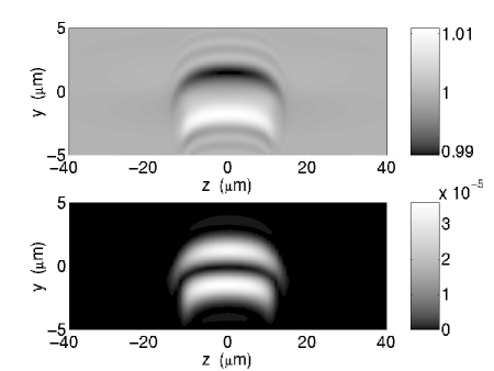
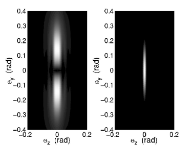
Experimentally, the phase profile of the transmitted probe beam can be determined by means of the same classical phase reconstructing techniques BornWolf that have recently been used to image the density profile of Bose condensates. The dark-ground scheme dark-ground-ketterle provides a picture in which the local intensity is proportional to the square of the accumulated phase, while the phase-contrast scheme disp-ketterle gives a picture in which the intensity variation is proportional to the accumulated phase. Although the signal is stronger in the case of the phase contrast picture, the dark–ground scheme has the advantage of dealing with a zero measurement, in which no light is detected for a vanishing velocity field.
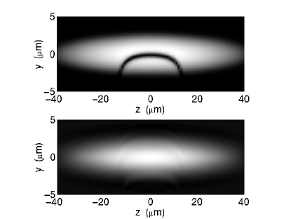
We report in Figs.2-5 results for the specific case of a Bose-condensed cloud containing a bent vortex BentVortex ; DalibBentVort (upper panel of Fig.2). Although our numerical results fully take into account diffraction effects, a clear interpretation of the resulting images can be put forward by neglecting diffraction. Under this approximation, the phase accumulated by the probe at a point after crossing the atomic cloud is
| (6) |
For a coupling beam propagating along the rotation axis and a probe propagating along the direction, the accumulated phase has opposite signs on the two sides of the vortex core from which stems the two-lobe structure of the images in Fig.3. For a condensate size much larger than the core radius, the velocity field around the vortex line has the typical behaviour. For such a velocity field, the phase shift (6) has a step-like shape with constant and opposite values:
| (7) |
on either side of the vortex line 555For the parameters of Fig.3, in good agreement with the numerical calculation.. Contrary to the case of conventional dispersive imaging in which the phase shift profile given by the decreased density at the vortex core (whose diameter is generally of the order of a fraction of slicing ; DalibBentVort ; CornellVort ) is strongly affected by diffraction effects (cf. lower panel of Fig.2), the phase shift in the slow light imaging case extends over the whole condensate and therefore is much more robust against diffraction. For this reason, a slow-light image of the vortex can be taken in situ without any preliminary ballistic expansion stage.
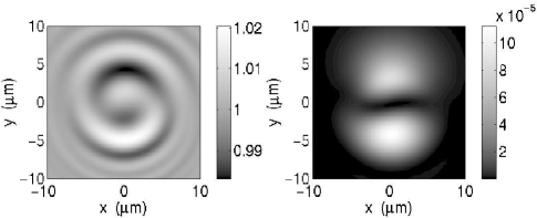
As the local polarization is proportional to , its magnitude remains unchanged if the directions of the coupling and probe beams are exchanged. Owing to the longer line of sight for a probe propagating along the rotation axis, the magnitude of the phase shift is expected to be somewhat larger in this geometry. This is shown in Fig.4, where the coupling is taken along the axis and the probe is along the rotation axis : the component of the circulating current still gives the main contribution to the phase–shift which has opposite signs respectively above or below the axis. Unfortunately, diffraction effects due to the rapid transverse density variations increase the size of the spots and give rise to fringes.
Finally, we would like to point out that in the case of slow–light imaging, the presence of a vortex can also be inferred from the far-field diffraction pattern dark-ground-ketterle of the probe after scattering. As in the Aharonov-Bohm-like picture, the presence of a circulation leads to the appearance of fringes in the diffraction pattern. We examine such a pattern in Fig.5. As expected, the presence of the vortex gives rise to a pair of symmetric side spots due to the interference between the light passing from either side of the vortex line and experiencing opposite phase-shifts. If a conventional imaging technique sensitive to the density were to be used instead, a single spot without structure would be obtained and the fast density modulation at the vortex core would only result into an increased spot size.
The present results can clearly be extended to configurations with more than one vortex slicing or even to multicomponent Bose-Einstein condensates exhibiting complex topological excitations Monopoles . The nearly complete absence of absorption and the possibility of attaining images that are quite robust to diffraction make slow–light imaging generally sound for the non-invasive observation of spatially small structures in ultracold clouds of trapped atoms while their real-time dynamics can directly be followed in situ.
We are indebted to G. C. La Rocca and F. Bassani for fruitful suggestions at various stages of the work and to M. Modugno for providing us with the numerical results for the density and current density profile of a bent vortex. We also acknowledge stimulating discussions with M. Inguscio, S. Rolston, Y. Castin, J.Dalibard, and S. Harris. I.C. and M.A. acknowledge financial support from the EU (Contracts HPMF-CT-2000-00901 and HPRICT1999-00111) as well as from the INFM. Laboratoire Kastler Brossel is a unité de Recherche de l’Ecole normale supérieure et de l’Université Pierre et Marie Curie, associée au CNRS.
References
- (1) M. R. Andrews, et al., Science 273, 84 (1996).
- (2) M. R. Andrews, et al., Phys. Rev. Lett. 79, 553 (1997).
- (3) C. Bradley, C. A. Sackett, and R. G. Hulet, Phys. Rev. Lett. 78, 985 (1997).
- (4) J. R. Abo-Shaeer, C. Raman, J. M. Vogels, and W. Ketterle, Science 292, 476 (2001).
- (5) P. Rosenbusch, V. Bretin, and J. Dalibard, cond-mat/0206511.
- (6) P. Engels, I. Coddington, P. C. Haljan, E. A. Cornell, cond-mat/0204449.
- (7) S. Harris, Physics Today 50, 36, (1997). E. Arimondo, Progress in Optics XXXV, Ed. E. Wolf (Elsevier Science, 1996) page 257 and references therein.
- (8) L. V. Hau, S. E. Harris, Z. Dutton, and C. H. Behroozi, Nature 397, 594 (1999); S. Inouye et al., Phys. Rev. Lett. 85, 4225 (2000)
- (9) A. V. Turukhin, V. S. Sudarshanam, and M. S. Shahriar, Phys. Rev. Lett. 88, 023602 (2002)
- (10) Slow–light media may also lead to the realization of intriguing laboratory analogues of relativistic effects. See U. Leonhardt, Nature 415, 406 (2002) and http://www.st-and.ac.uk/ ulf/
- (11) M. A. Player, Proc. Roy. Soc. London A 345, 343 (1972); G. L. Rogers, ibidem 345, 345 (1972).
- (12) F. Dalfovo, S. Giorgini, L. P. Pitaevskii, and S. Stringari, Rev. Mod. Phys. 71, 463 (1999).
- (13) A. Fetter and A. Svidzinsky, J. Phys.: Condens. Matter 13, R135-R194 (2001).
- (14) J. D. Jackson, Classical Electrodynamics, J. Wiley (2nd Edition), New York (1975).
- (15) D. M. Stamper-Kurn et al., Phys. Rev. Lett. 81, 500 (1998).
- (16) R. Jones, Proc. R. Soc. London, A 328, 337 (1972) and ibidem, A 345, 351 (1975).
- (17) N. Treps et al., Phys. Rev. Lett. 88, 203601 (2002).
- (18) A similar beam configuration has been proposed to retrieve the local phase of a condensate [See P.Öhberg, cond-mat/0205190 (2002)].
- (19) M. Modugno, L. Pricoupenko, and Y. Castin, cond-mat/0203597 (2002).
- (20) M. Born and E. Wolf, Principles of optics, Cambridge University Press, Cambridge (1959).
- (21) U. Al Khawaja and H. T. C. Stoof, Phys. Rev. A 64, 043612 (2001)