Simple Phase Bias for Superconducting Circuits
Abstract
A phase-bias tool, based on a trapped fluxoid in a ring, is proposed and demonstrated. It can provide arbitrary phase values and is simple to fabricate. The phase bias has been realized in two superconducting quantum interference devices, where the critical current versus magnetic flux is shown to be shifted by a and .
Many superconducting devices require an imposed phase difference. Usually this phase bias is applied by means of magnetic flux in a closed superconducting loop. An example is the superconducting quantum interference device (SQUID) [1], which needs a phase bias of around /2. Several types of superconducting quantum bits rely on a phase difference [2, 3, 4]. So-called -junctions, where the dependence of the current on the phase difference is shifted by , are seen as attractive components in superconducting electronics [5]. -junctions have been developed with d-wave superconductors [6] and with superconductor-ferromagnet-superconductor junctions [7], but here severe materials problems are encountered. We have developed a surprisingly simple phase-bias tool, based on trapped fluxoids in a closed loop without junctions. It can be fabricated very easily from materials such as niobium or aluminum; any phase shift can be realized. We present a demonstration of its performance in SQUID devices with built-in phases of and /2.
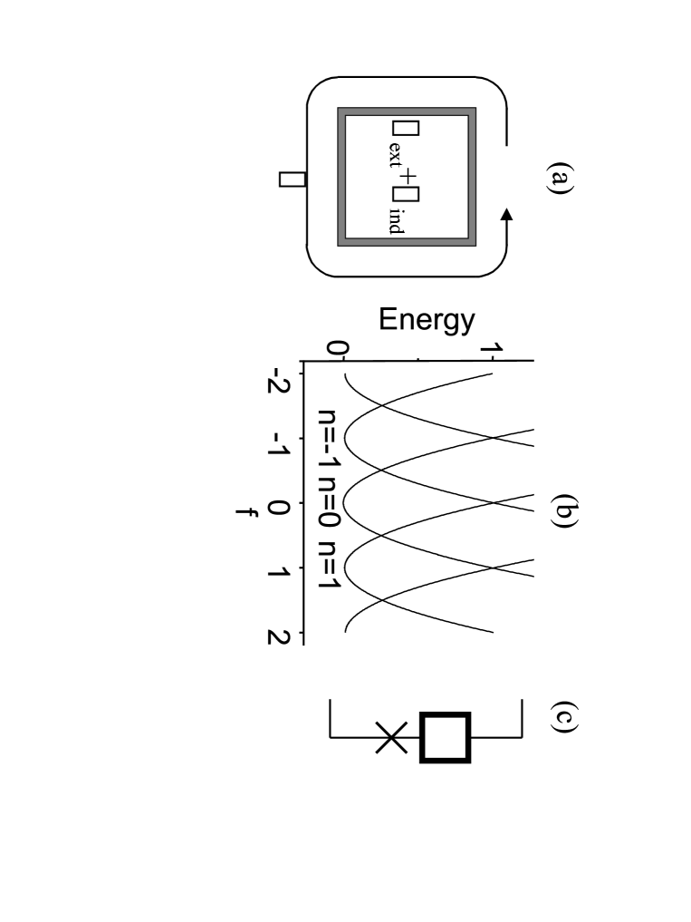
Our approach relies on a mesoscopic superconducting ring [Fig. 1 (a)] with narrow cross section relative to the penetration depth. The phase difference along the circumference is proportional to the current in the ring. The proportionality factor is given by the kinetic inductance of the ring .
| (1) |
where is the superconducting flux quantum. The kinetic inductance of the ring depends on the London penetration depth and geometrical factors, such as the circumference , width and height of the cross section of the wire [8]:
| (2) |
The flux in the ring contains two contributions: the externally imposed flux and the flux generated by the current, where is the geometrical inductance of the ring. The fluxoid quantization condition [8] yields:
| (3) |
where is the integer fluxoid number and the ratio between geometrical and kinetic inductance. Changes in are only possible through phase slip processes, requiring the order parameter to go to zero in a region of the order of the coherence length. The energy required for a phase slip at zero current is approximately equal to [9], where is the critical current of the wire. As critical currents of even narrow wires are typically in the order of 1 mA, the barrier is very high .
The energy of the the ring has a parabolic dependence on the applied flux [Fig. 1 (b)].
| (4) |
If approximately one flux quantum is applied to the ring () while cooling down through the superconducting phase transition, the ring assumes the lowest energy state . When the external flux is removed at low temperatures, the new ground state cannot be reached and the ring remains frozen in the state. When a relatively weak superconducting circuit is attached to two contacts on the ring, that circuit experiences a phase shift bias through two channels: the directly picked-up fraction of the total phase and the magnetic flux induced in the loop in the attached circuit. The first contribution is for a homogeneous ring with circumference and an enclosed section between the contacts. It dominates when the kinetic inductance is large, . The contribution from the flux dominates when . In practice both limits can be realized, but intermediate values of are equally useful. For the example of our aluminum SQUID circuits is of order one. With this ring, new superconducting circuit elements can be made. In Fig. 1 (c) a ring is connected to a standard Josephson junction. This element behaves like a -junction in a superconducting network.
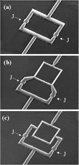
This idea is applied to a SQUID. We fabricated three devices [Fig. 2] on a single substrate using standard aluminum shadow evaporation technique. The ring is evaporated in the same layer as the Al/Al2O3/Al Josephson junctions, which makes the fabrication very simple. This is illustrated by the fact that the first fabrication attempt was successful. The first device [Fig. 2 (a)] is a standard SQUID and serves as a reference for the two other samples. The second device [Fig. 2 (b)] includes a ring in the SQUID, where one quarter of the ring is enclosed. We will refer to this device as the /2-SQUID. The third device [Fig. 2 (c)], called the -SQUID, encloses half of the ring.
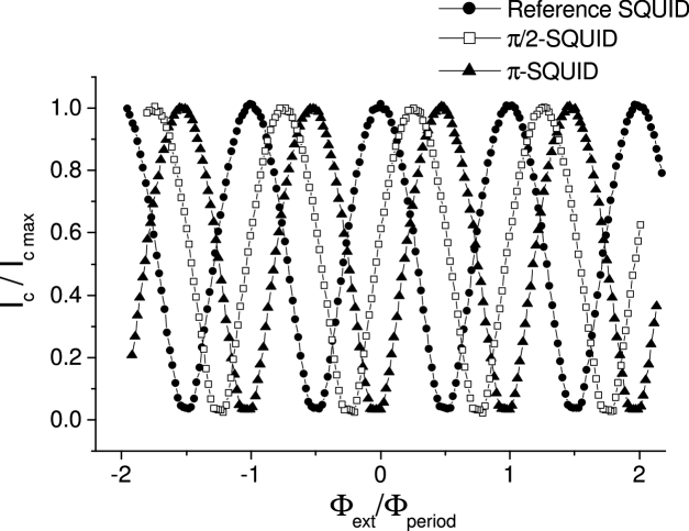
Measurements were performed in a dilution refrigerator at 60 mK. We measured the switching current as a function of the applied magnetic field . All three devices show regular SQUID oscillations, with maxima and minima clearly shifted with respect to each other. For analysis, the critical current was Fourier analyzed. Results are given in table I. In Fig. 3 the normalized critical current is plotted as a function of the normalized applied flux. Clear shifts of approximately a quarter period for the -SQUID and a half period for the -SQUID are observed.
Assuming that the current levels in the wire are much higher than the critical current of the Josephson junctions , i.e. , results in the following expression for the critical current of a SQUID with a ring included:
| (5) | |||
| (6) |
Here is the external flux in the SQUID loop and the external flux in the ring. is the mutual inductance between the ring and the SQUID loop. The first part in the cosine argument gives the regular SQUID behavior. The second part is caused by the ring. The critical current pattern is shifted by . Additionally the ring contributes times the area of the ring to the oscillation period. Furthermore in derivation of equation 5 the effects of the self inductance of the SQUID loop are neglected.
If the ring is small compared to the SQUID loop, the ratio between the mutual inductance and the self inductance of the ring is equal to the ratio between the enclosed section and the total circumference . Then the factor is just equal to these ratios .
In our experiment the ring is not small compared to the SQUID loop. The ratio for the /2-SQUID is 0.20 and for the -SQUID 0.35. To check the consistency of our experiment with theoretical expressions (5), one can calculate from either the period or the phase shift. For the -SQUID we obtain =0.462 from the period and =0.467 from the phase shift. For the /2-SQUID we get =0.248 from the period and =0.253 from the phase shift.
We also cooled down with zero flux applied to the rings. All three devices showed regular SQUID behavior with a maximum switching current at zero field, i.e. zero phase shift. Equally consistent with predictions were the patterns produced cooling down with minus one flux quantum and two flux quanta. We tested the stability of the frozen fluxoid by suddenly shorting and switching on the magnet supply, but we saw no change in the state.
The flux applied to the ring during the cool down does not have to be exactly a flux quantum because is an integer. Deviating from the integer value will merely increase the chance of freezing a different number of fluxoids in the ring.
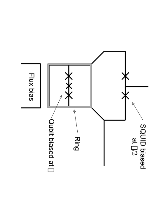
Phase-bias rings can also be applied for flux qubits [3], which need a shift of to reach the degeneracy point where superposition states occur. The ring bias is expected to have much lower flux noise than an external magnetic field. Fig. 4 shows a simple version of a gradiometer qubit where both the qubit and the measuring SQUID are biased by the same ring.
ACKNOWLEDGMENTS
We acknowledge useful discussions with P. Hadley, Y. Nakamura, C. J. P. M. Harmans, T. P. Orlando and A. Morpurgo and technical assistance from A. van der Enden and R. Schouten. This research was supported by Stichting voor Fundamenteel Onderzoek der Materie (FOM).
REFERENCES
- [1] M. Tinkham, Introduction to Superconductivity, (McGraw-Hill, Newyork, 1996)
- [2] L. B. Ioffe, V. B. Geshkenbein, M. V. Fiegel’man, A. L. Fauchere, and G. Blatter, Nature (London) 398, 670 (1999).
- [3] J. E. Mooij, T. P. Orlando, L. Levitov, L. Tian, C. H. van der Wal, and S. Lloyd, Sience 285, 1036 (1999).
- [4] G. Blatter, V. B. Geshkenbein, L. B. Ioffe, Phys. Rev. B 63, 174511 (2001)
- [5] E. Terzioglu, M. R. Beasley, IEEE Trans. Appl. Supercond. 8, 48 (1998).
- [6] E. Il’ichev et al, Phys. Rev. Lett. 86, 5369 (2001).
- [7] V. V. Ryazanov, V. A. Oboznov, A. Yu. Rusanov, A. V. Veretennikov, A. A. Golubov and J. Aarts, Phys. Rev. Lett. 86, 2427 (2001).
- [8] T. P. Orlando, K. A. Delin, Foundations of Applied Superconductivity (Addison-Wesley Publishing Company 1990)
- [9] D. E. McCumber, B. I. Halperin, Phys. Rev. B. 1, 1054 (1970).
| Sample | Period | Phase |
|---|---|---|
| Reference SQUID | 118.2 T | 0.1 T |
| /2-SQUID | 128.1 T | 32.5 T |
| -SQUID | 120.5 T | 56.4 T |