Spin alignment of dark matter haloes in filaments and walls
Abstract
The MMF technique is used to segment the cosmic web as seen in a cosmological N-body simulation into wall-like and filament-like structures. We find that the spins and shapes of dark matter haloes are significantly correlated with each other and with the orientation of their host structures. The shape orientation is such that the halo minor axes tend to lie perpendicular to the host structure, be it a wall or filament. The orientation of the halo spin vector is mass dependent. Low mass haloes in walls and filaments have a tendency to have their spins oriented within the parent structure, while higher mass haloes in filaments have spins that tend to lie perpendicular to the parent structure.
Subject headings:
Cosmology: large-scale structure of Universe – Galaxy formation1. Introduction
The origin of the angular momentum of galaxies and their associated dark matter haloes remains one of the most poorly understood subjects in present galaxy formation theories despite its relevance in determining properties such as size and morphological type. According to the Tidal Torque Theory (TTT), galaxies acquire their angular momentum as a consequence of the tidal shear produced by the neighbouring primordial matter distribution (Hoyle, 1949; Peebles, 1969; Doroshkevich, 1970; White, 1984). A natural consequence of the TTT is a correlation between the angular momentum of haloes and their surrounding matter distribution (Efstathiou & Jones, 1979; Barnes & Efstathiou, 1987; Heavens & Peacock, 1988; Lee & Pen, 2001; Porciani et al., 2002). Lee & Pen (2001) and Lee (2004) made specific predictions about this.
Orientation studies based on galaxy catalogues show anti-alignment (Kashikawa & Okamura, 1992; Navarro et al., 2004; Trujillo et al., 2006). The situation in N-body models is less clear: some dark matter N-body simulations seem not to detect any systemic halo spin alignment (Patiri et al., 2006; Heymans et al., 2006), while others (Lee & Pen, 2001; Bailin & Steinmetz, 2005; Hatton & Ninin, 2001; Faltenbacher et al., 2002) present evidence that dark matter haloes are aligned with host structures. More recently Altay et al. (2006) found a strong shape alignment of dark haloes in filaments, while Brunino et al. (2006) reported the discovery of a systematic alignment effect in an analysis of dark matter haloes taken from the very large “Millennium” N-body simulation (Springel et al., 2005). We suggest that such ambiguities may in large part be a consequence of the methods used to identify the larger scale structures that host the haloes.
2. Finding and classifying structure
Large galaxy surveys such as the 2dF (Colless et al., 2001) or more recently the Sloan Digital Sky Survey (York et al., 2000) have unambiguously revealed an intricate network of galaxies: the cosmic web. The cosmic web can be described as a mixture of three basic morphologies: clusters which are predominantly spherical, elongated associations of galaxies (filaments) and large planar structures (walls) (Zeldovich, 1970; Shandarin & Zeldovich, 1989).
Bond et al. (1996) emphasized that this weblike pattern is shaped by the large scale tidal force fields whose source is the inhomogeneous matter distribution itself (see also van de Weygaert (2006)). Acccording to TTT the same tidal field also generates the angular momentum of collapsing halos. Thus we would expect the shape and angular momentum of cosmic haloes to be correlated with one another and with the cosmic web elements in which they are embedded.
Revealing such correlations requires the ability to unambigiously identify the structural features of the cosmic web. Several methods have in the past been used in an attempt to identify and extract the morphological components of the observed galaxy distribution (Barrow et al., 1985; Babul & Starkman, 1992; Luo & Vishniac, 1995; Stoica et al., 2005; Colberg et al., 2005; Pimblet, 2005) with varying degrees of success. The results presented in this letter are based on a new method, the Multiscale Morphology Filter: “MMF” (Aragón-Calvo et al., 2006). MMF allows us to objectively segment the cosmic web into its three basic morphological components by analysing the properties of the matter distribution hierarchically. With this morphological characterisation we can isolate specific host environments (filaments and walls) for haloes and test predictions from the TTT in a systematic way.
The MMF method is a significant advance on other similar studies of N-body models. MMF is a technique that locates and classifies various structures by exploiting localised properties of the inertia tensor of the matter distribution on a hierarchy of scales. Since the inertia tensor is directly related to the dynamical forces that drive the tidal torques, MMF is particularly suited for this investigation. The significance of the effects reported here is strong, despite the relatively small size of the N-body simulation, because of the clear cut MMF environmental descriptor.
3. N-body simulations and structure
We ran a cosmological N-body simulation containing equal mass dark matter particles inside a cubic box of h-1 Mpc. using the public version of the parallel Tree-PM code Gadget2 (Springel, 2005). We adopted the standard cosmological model , , and . The analysis presented here is based on the last snapshot at . The mass per particle is h-1 M⊙ and the softening length was set to 18 h-1 kpc (comoving) until and 6 h-1 kpc (physical) after that time.
3.1. Detecting Filaments and Walls
The Multiscale Morphology Filter is based on the second-order local variations of the density field as encoded in the Hessian matrix () for the smoothed density field. For a given set of smoothing scales we compute the eigenvalues of the Hessian matrix at each position on the density field. The density field is computed from the particle distribution by means of the DTFE method (Schaap & van de Weygaert, 2000, 2006): this is natural and self-adaptive, and retains the intricate anisotropic and hierarchical features characteristic of the cosmic web. DTFE smoothing plays an essential role in delineating filaments and walls unambiguously.
We use a set of morphology filters based on relations between the eigenvalues in order to get a measure of local spherical symmetry, filamentariness or planarity. The morphological segmentation is performed in order of increasing degrees of freedom in the eigenvalues for each morphology (i.e. blobs filaments walls). The response from the morphology filters computed at all scales is integrated into a single multiscale response which encodes the morphological information present in the density field. At each stage of the filtering we discard the particles that have previously been assigned to a structure and compute a new density field.
In a filament, the eigenvectors of the Hessian matrix corresponding to the smallest eigenvalue () indicate the direction of filament. In walls the largest eigenvalue, indicates the perpendicular to the wall (). Eigenvectors are computed from a smoothed version of the density field; this avoids small-scale variations in the directions assigned to filaments and walls.
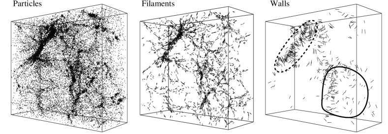
In Figure 1 we show a region of the simulation containing several filaments and two large walls detected using the MMF. The box and its projection were chosen in order to avoid confusion from projection of many structures on top of each other and to show one wall face-on and one edge-on. Filaments are clearly delineated like streaming lines joining large associations of matter. Walls are more difficult to visualise so we also plot their defining eigenvectors. For this projection we can see that the eigenvectors () defining the wall seen head-on (solid line) are pointing towards us, while the ones corresponding to the wall seen edge-on are perpendicular to the line-of-sight (dashed line).
3.2. Halo Identification
Haloes were identified with a somewhat different implementation
of the publicly available halo finder HOP (Eisenstein & Hut, 1998).
First we identify haloes by running hop with the standard parameters
and =80, =120 and =160 for
regrouping. Each of these haloes is considered a parent candidate which may comprise
more than one single subhalo. Next for all particles we compute densities using a
Gaussian window
with dispersion of 35 h-1 kpc, in order to produce a smoothed density field without
substructure smaller than this kernel. We run hop again but only for particles
inside the parent candidates and this time we also provide the smoothed densities
previously computed as an input for hop. The halo identification is performed without
running regroup. By doing this hop will assign all particles to their smoothed
local maximum, each group found in this stage is a candidate subhalo. For each of these
new subhaloes we find their center of mass iteratively and remove the unbound particles.
This “FracHop” method allows us to find bound subhaloes inside larger groups otherwise
identified as single virialised objects.
Finally, we keep haloes with more than 50 particles and less than 5000, a mass range of (1-100) h-1 M⊙.
3.3. Halo properties
The angular momentum of a halo containing particles is then defined as:
| (1) |
where is the particle’s mass, is the distance of each particle from the center of the halo, is the peculiar velocity of the particle and the mean velocity of the halo with respect to the center of mass. We compute the angle between the halo’s spin and its assigned Filament or Wall,
| (2) |
where
| (3) |
being the vector defining the orientation of the filaments (F) and walls (W). For each halo principal axes are computed by diagonalising the inertia moment tensor
| (4) |
where the positions of the particles are with respect to the center of mass and the sum is over all particles in the halo. The orientation of any of the eigenvectors of relative to the host structure is described by angles analogous to the angles , , and defined above.
4. Results
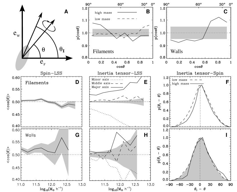
Our main results are presented in Figure 2 and may be summarised as follows:
-
•
The orientations of halo spins are significantly correlated with the large scale structure in which they are situated. Haloes in walls have spin vectors that tend to lie in the plane of the host wall (frame C). The strength of the alignment of haloes in walls is relatively small (the Lee-Pen correlation parameter is ) but nevertheless statistically significant: the K-S probability that the halo orientations in walls are randomly distributed is less than . We find similar correlations in filaments, though of a more subtle character (frame B).
-
•
The orientation of halo spin vectors in filaments is mass dependent: low mass halo spins tend to lie parallel to their host filament while high mass halo spins tend to lie perpendicular to their host filament (frames B & D). High mass haloes, , have a K-S probability less than of being randomly orientated, low mass haloes less than (frame B).
-
•
The principal axes of haloes in filaments are strongly correlated with the direction of the filaments: the minor axis tends to be directed perpendicular to the filament, the effect being strongest for the larger masses (frame E)
-
•
The principal axes of haloes in walls are strongly correlated with the perpendicular to walls: the minor axis tends to be lie perpendicular to the wall while the other axes tend to lie in the local plane of the wall (frame H).
-
•
While both the halo minor axis and the spin are correlated with the megaparsec scale structure, the distribution of the angle between these two is skewed and biased towards the surrounding large scale structure. This slight skewness may bias the estimate of the mean angle the spin makes with the host structure (frames F and I).
5. Concluding remarks
The significance of the alignments we have found, given the relatively small sample of haloes and small simulation volume, emphasises the benefits of having a good definition of environmental structures when studying halo properties and their relation with the cosmic web.
The results reported here are in accord with results reported by e.g. Brunino et al. (2006). We find that halo spin vectors lie within the host structure and halo minor axes point out of the host structure as previously suggested by (Patiri et al., 2006; Brunino et al., 2006). Thé major advance of our study is the objective and multiscale character of the structure identification by means of the MMF. Earlier studies at best resorted to heuristic means of delineating filaments or walls (Pimblet, 2005; Colberg et al., 2005; Brunino et al., 2006). Some earlier studies have measured the distance of a halo from a local minimum in the large scale density distribution. On the assumption that the surfaces of such “spherical” voids are to be identified with the large scale structures hosting the haloes one may attempt to find signatures of spin and shape alignments. Voids are not generally spherical, nor is it always clear which of several voids a halo is related to. Moreover, using voids as defining the environment of a halo does not in itself allow for the important distinction between walls and filaments. Alignment detections should therefore be seen as residuals of genuine physical alignments with walls or filaments.
This letter poses a number questions for future investigation. The mass segregation of alignments in filaments is yet to be understood. Detailed merging trees may give clues to the possible non-linear processes responsible for this effect. It will of course be interesting to use MMF to define environments in catalogues of galaxies such as 2dF and SSDS: this should provide an important refinement of earlier results of Trujillo et al. (2006) and since it will unambiguously localise galaxies as either being in walls or in filaments.
References
- Altay et al. (2006) Altay G., Colberg J. M., Croft R. A. C. 2006, MNRAS, 370, 1422
- Aragón-Calvo et al. (2006) Aragón-Calvo M.A., van de Weygaert R., Jones B.J.T., van der Hulst J.M., 2006, to be subm.
- Babul & Starkman (1992) Babul A., Starkman G. D. 1992, ApJ, 401, 28
- Bailin & Steinmetz (2005) Bailin J., Steinmetz M. 2005, ApJ, 627, 647
- Barnes & Efstathiou (1987) Barnes J., Efstathiou G. 1987, ApJ, 319, 575
- Barrow et al. (1985) Barrow J. D., Bhavsar S. P., Sonoda D. H. 1985, MNRAS, 216, 17
- Bond et al. (1996) Bond J. R., Kofman L., Pogosyan D. 1996, Nature, 380, 603
- Brunino et al. (2006) Brunino R., Trujillo I., Pearce F., Thomas P.A., 2006, astro-ph/0609629
- Chen et al. (2003) Chen D. N., Jing Y. P., Yoshikaw K. 2003, ApJ, 597, 35
- Colberg et al. (2005) Colberg J. M., Krughoff K. S., Connolly A. J. 2005, MNRAS, 359, 272
- Colless et al. (2001) Colless M., et al. 2001, MNRAS, 328, 1039
- Doroshkevich (1970) Doroshkevich A. G. 1970, Astrophysics, 6, 320
- Efstathiou & Jones (1979) Efstathiou G., Jones B. J. T. 1979, MNRAS, 186, 133
- Eisenstein & Hut (1998) Eisenstein D. J., Hut P. 1998, ApJ, 498, 137
- Faltenbacher et al. (2002) Faltenbacher A., Gottloeber S., Kerscher M., Müller V., 2002, A&A, 395, 1
- Hatton & Ninin (2001) Hatton S., Ninin S. 2001, MNRAS, 322, 576
- Heavens & Peacock (1988) Heavens A., Peacock J., 1988, MNRAS, 232, 339
- Heymans et al. (2006) Heymans C., et al. 2006. astro-ph/0604001
- Hoyle (1949) Hoyle F., 1949, Problems of Cosmical Aerodynamics
- Kashikawa & Okamura (1992) Kashikawa N., Okamura S. 1992, PASJ, 44, 493
- Lee & Pen (2001) Lee J., Pen U.-L. 2001, ApJ, 555, 106
- Lee (2004) Lee J. 2004, ApJ, 614, L1
- Luo & Vishniac (1995) Luo S., Vishniac E. 1995, ApJS, 96, 429
- Navarro et al. (2004) Navarro J. F., Abadi M. G., Steinmetz M. 2004, ApJ, 613, L41
- Patiri et al. (2006) Patiri S. G., et al. 2006. astro-ph/0606415
- Peebles (1969) Peebles P. J. E. 1969, ApJ, 155, 393
- Pimblet (2005) Pimblet K.A., 2005, MNRAS, 358, 256
- Porciani et al. (2002) Porciani C., Dekel A., Hoffman Y. 2002, MNRAS, 332, 325
- Schaap & van de Weygaert (2000) Schaap W. E., van de Weygaert R. 2000, A&A, 363, L29
- Schaap & van de Weygaert (2006) Schaap W. E., van de Weygaert R. 2006, A&A, subm.
- Shandarin & Zeldovich (1989) Shandarin S.F., Zel’dovich Ya. B., 1989, Revs. Mod. Phys., 61, 185
- Springel (2005) Springel V. 2005, MNRAS, 364, 1105
- Springel et al. (2005) Springel V., et al., 2005, Nature, 435, 629
- Stoica et al. (2005) Stoica R., Martínez V., Mateu J., Saar E. 2005, A&A, 434, 423
- Trujillo et al. (2006) Trujillo I., Carretero C., Patiri S. G. 2006, ApJ, 640, L111
- van den Bosch et al. (2002) van den Bosch F. C., Abel T., Croft R. A. C., Hernquist L., White S. D. M. 2002, ApJ, 576, 21
- van de Weygaert (2006) van de Weygaert R., 2006, in Measuring th diffuse intergalactic medium, eds. J.W. den Herder & N. Yamasaki
- White (1984) White S. D. M. 1984, ApJ, 286, 38
- York et al. (2000) York D. G., et al. 2000, AJ, 120, 1579
- Zeldovich (1970) Zel’dovich Ya. B., 1970, A&A, 5, 84