The Onset of Gamma-Ray Burst Afterglow
Abstract
We discuss the reference time of afterglow light curves in the context of the standard internal-external shock model. The decay index of early afterglow is very sensitive to the reference time one chooses. In order to understand the nature of early afterglow, it is essential to take a correct reference time. Our simple analytic model provides a framework to understand special relativistic effects involved in early afterglow phase. We evaluate light curves of reverse shock emission as well as those of forward shock emission, based on full hydrodynamic calculations. We show that the reference time does not shift significantly even in the thick shell case. For external shock emission components, measuring times from the beginning of the prompt emission is a good approximation and it does not cause an early steep decay. In the thin shell case, the energy transfer time from fireball ejecta to ambient medium typically extends to thousands of seconds. This might be related to the shallow decay phases observed in early X-ray afterglow at least for some bursts.
1 Introduction
It is well known that gamma-ray burst (GRB) afterglow decays as a power-law . The temporal decay index , together with the spectral index, provides us precious information about GRB jets and their environment. In the pre-Swift era afterglow observations start typically a few hours after a burst. In such a late phase, the decay index is insensitive to the choice of the reference time , and GRB trigger time is often used in afterglow modelings.
The multi-wavelength observatory Swift was launched in Nov 2004. Thanks to its fast pointing capabilities Swift is disclosing the early afterglow phase. One of unexpected finds by Swift is that early X-ray afterglows show a canonical behavior, where light curves include three components: (1) a steep decay component, (2) a shallow decay component and (3) a “normal” decay component. On top of this canonical behavior, many events have superimposed X-ray flares (Zhang et al. 2006a; Nousek et al. 2006; Chincarini et al 2005; O’Brien et al. 2006). The transition from the early steep decay to the shallow decay typically occurs at several hundred seconds, and the timescale is comparable to the duration of rather long GRBs. When discussing the early afterglow and its connection to the prompt emission component, the decay index is very sensitive to the reference time one chooses. Correctly choosing is therefore essential to derive the right index as well as to interpret each component in the canonical light curve (Piro et al. 2005; Tagliaferri et al. 2005; Quimby et al. 2006).
Tagliaferri et al. (2005) investigated the first two bursts GRB 050126 and GRB 050219a which have an X-ray light curve well sampled by the X-Ray Telescope on board Swift. They sought for a possible delay of the afterglow onset by fitting the early X-ray light curves (the components 1 and 2 which we have discussed above) with a single power-law model. In both cases, the decaying light curves can be fitted if the onset of the afterglow is shifted to s after the burst trigger with a single power-law. However, while in the case of GRB 050126 the light curve does not allow us to clearly state whether a broken power-law modeling is better than a single power-law model, for GRB 050219a a broken power-law definitively provides a better fit.
In the standard GRB model the time shift between the GRB trigger and the reference time is expected to be “small”. The early steep decay should not be an artifact due to a wrong choice of . Lazzati and Begelman (2006) studied forward shock emission, based on a simple energy injection model. Their numerical light curves show that measuring times from the beginning of the prompt phase is a good approximation. The early steepening and X-ray flares are likely to be produced by another mechanism (e.g. internal shocks; Burrows et al. 2005; Falcone et al. 2006; Zhang et al. 2006a; Nousek et al. 2006; Ioka, Kobayashi & Zhang 2005; Fan & Wei 2005). Recently long-lasting soft emission is reported in a short burst GRB 050724 (Barthelmy et al. 2005). Such a soft component was hinted at in the sum of multiple short BATSTE GRBs, and it might be the onset of short burst afterglow (Lazzati, Ramirez-Ruiz & Ghisellini 2001). It is therefore of interest to quantitatively examine the issue.
In this paper, we study the physics and timescales involved in early afterglow stage, and give more direct and clear arguments for the afterglow slopes. In §2 we study a simple analytic model. In §3 we evaluate light curves of reverse shock emission as well as that of forward shock emission, based on full hydrodynamic calculations. In §4 we address how inhomogeneity of a fireball affects an early afterglow light curve. Conclusions and discussion are given in §5.
2 The Reference Time
Let be a radius of a forward shock expanding with a Lorentz factor into homogeneous ambient medium. Since the shock is moving toward us at almost the speed of light , the difference of the the observed times between a photon emitted at and another emitted at is . Although the origin of observed time is arbitrary, a natural definition of observed time is given by the delay of photons emitted from a shock front at a lab time with respect to the photons emitted from the “explosion” at and . The dashed line in figure 1 depicts the trajectory of the photon from the explosion. In this paper, and denote the lab and observed time since the explosion, respectively. Distance, velocity and the corresponding Lorentz factors are measured in the lab frame. Thermodynamic quantities (pressure and density) are measured in the local fluid frame. The observed time is given by
| (1) |
The shock radius is almost proportional to the lab time, . Considering that internal shocks occur and produce gamma-rays at radii much smaller than the deceleration radius of the fireball, the prompt gamma-rays associated with the outermost element of the fireball should propagate practically on the dashed line in figure 1. The GRB trigger almost coincides with the explosion . The difference is small, and order of the variability timescale of the prompt emission, because the variability timescale directly reflects the inhomogeneity scale in a fireball (Kobayashi, Piran & Sari 1997). The dashed line in figure 1 will be called the gamma-ray front in the following sections.
A fireball with an initial Lorentz factor decelerates when it collects a large volume of ambient material with a mass density . Equalizing energy of the shocked ambient material and fireball energy , we obtain the deceleration radius where is the Sedov length. Since the fireball density decreases as it expands, there is a possibility that a reverse shock evolves from Newtonian to relativistic during the propagation. A relativistic reverse shock reduces considerably the Lorentz factor of the fireball material which it crosses. In such a case, the energy of the shocked ambient medium is still negligible at , because we have assumed at the deceleration to estimate . The reverse shock crosses the fireball shell at and all the fireball material decelerates where is a fireball shell width (see Sari & Piran 1995 and Kobayashi, Piran & Sari 1999 for the details). In summary, the evolution of fireballs are classified into two cases depending on the value of relative to a critical value (Sari & Piran 1995). If is smaller than the critical value, it is called the thin shell case 111In the thin shell case, the deceleration observed time is given roughly by the critical width , and it is longer than the duration of the prompt emission (Sari 1997). The deceleration time approaches if we take a larger , and around (or equivalently ) a reverse shock becomes relativistic during the propagation. The Lorentz factor of the shocked material at the crossing time becomes independent from the initial value, and it is given by . The deceleration observed time is about .. The reverse shock is always in the Newtonian regime, and it is too weak to slow down the fireball effectively. The deceleration radius is . If (the thick shell case), we define the deceleration radius as the shock crossing radius . The deceleration lab time is given by .
If the Blandford-McKee (BM) blast wave scaling (Blandford and McKee 1977) was valid for the whole fireball evolution (the thin solid line in figure 1), integrating eq. (1), we obtain . Since the spectral characteristics of forward shock synchrotron emission are given by products of , , and constant parameters (Sari, Piran & Narayan 1998), the light curve should be described by a power-law with the reference time . However, the BM blast wave scaling is applicable only after the fireball is decelerated (e.g. Kobayashi, Piran & Sari 1999). At earlier times the fireball (the thick solid line) is in the coasting phase, and it is slower than evaluated from the BM blast wave scaling. The delay of photons from the shock front at the deceleration lab time is larger by than in the case that the BM blast wave scaling is applicable to the whole evolution (see figure 1) where and are the separations at the deceleration lab time between the gamma-ray front (dashed line) and the reference BM blast wave (the thin solid line), and between the gamma-ray front and the fireball forward shock (the thick solid line), respectively. The reference time for the afterglow modeling is given by
| (2) |
In the thick shell case, a forward shock keeps being energized for a longer time, and the deceleration phase starts at a later time. It still overestimates the shift of the reference time if is set at the end of the energy injection or equivalently at the peak time of afterglow. In figure 2 the dot indicates the point at which the energy injection stops and the fireball turns into a BM solution. Measuring times from the peak of afterglow corresponds to defining a reference null geodesic (the dashed line) as it goes through the dot. Imagine the reference BM blast wave (the thin solid line) associated with the new reference null geodesic 222BM blast wave lines on the spacetime diagram are determined by two parameters, an explosion time (i.e. a null geodesic on the diagram) and the Sedov length. The latter is evaluated with the total fireball energy if there is energy injection before the deceleration time.. The decay of the emission from this reference blast wave should be characterized by a power-law using the new reference time (measuring times from the peak). The evolution of a real fireball (the thick solid line) is also described by a BM blast wave after the deceleration. However, it is a different solution (a different curve on the diagram). Applying the new reference time to the afterglow modeling leads to a wrong estimate of the decay index especially in the early phase. The decay index should become shallower than the real value.
Using eq.(1) and the evolution of a BM blast wave , we obtain where is the Lorentz factor at the deceleration radius . Since the Lorentz factor of a fireball is constant at , we get for the thin shell. In the thick shell case, a reverse shock becomes relativistic before it crosses the fireball shell, and it begins to reduce considerably the Lorentz factor of the shell’s matter which it crosses. The Lorentz factor of the forward shock is also significantly reduced as during the reverse shock crossing (Sari & Piran 1995; Kobayashi, Piran & Sari 1999), and we get for the thick shell. The reference time is given by
| (3) |
where is the deceleration observed time.
We have considered a simple broken power-law model for the evolution of a fireball Lorentz factor, and we obtained eq. (3). In reality the fireball should decelerate gradually around the deceleration radius. An artificial early steepening could happen only when , and in such a case should be set at (the afterglow peak time) to get the correct . However, in both of the thin shell and thick shell cases, we have found that and are comparable. Therefore, measuring times from the beginning of the prompt phase should not induce an overestimate of afterglow decay right after the peak.
Eq. (1) gives the delay of photons emitted from a point on the shock front on the line of sight, while most photons suffer longer delays, since they are emitted from a shocked region of finite thickness behind the shock, and from positions off the line of sight. Although these effects could make both separations and larger by a factor of a few (Waxman 1997), they are still comparable and our arguments are valid.
3 Numerical Model
We employ a spherical relativistic Lagrangian code based on the Godunov method with an exact Riemann solver to evaluate the hydrodynamic evolution of a relativistic fireball (Kobayashi et al. 1999; Kobayashi & Sari 2000). Using the Einstein summation convention the equations describing the motion of a relativistic fluid are given by the five conservation laws
| (4) |
where is four velocity and is the stress-energy tensor (), which for a perfect fluid can be written as . Here, is the metric tensor, the fluid pressure, and the heat function per unit volume. Shocked material is extremely hot and pressure is related to internal energy and mass density as . In the Godunov scheme, conservative variables are considered as piecewise constants over the mesh cells at each time step and the time evolution is determined by the solution of the Riemann problem (shock tube) at the inter-cell boundaries (e.g. Martí & Müller 1999 and references therein).
Because of the relativistic beaming effect, the radiation from a jet before the jet break can be described by a spherical model with an isotropic energy. The initial configuration for our simulation is a static uniform fireball surrounded by uniform cold ambient material (ISM). It is determined by four parameters: an isotropic energy , a dimensionless entropy , an initial radius and the ISM mass density . and always appear as the ration in the hydrodynamics computation, the system is actually determined by three parameters, the initial radius , the entropy and the Sedov length . For convenience, we set the initial lab time as rather than zero in numerical calculations, and the observed time is determined by the delay of photons from an emitter with respect to the photons emitted from the initial fireball surface at and . Since the fireball immediately accelerates to a relativistic velocity, this is practically equivalent to the observed time used in figure 1.
We carry out numerical calculations for the total number 333We have reevaluated the light curves Figs 5 and 7 for . In the log-log space, the resulting light curves are almost identical. The differences are less than several percent. When we remove numerical oscillations, they are in a few percent agreement. of mesh cells . A third of the cells are for the fireball, while the other cells describe the ambient medium within cm. Although the initial configuration is cells per decade, the nature of Lagrangian method gives a much higher resolution for shocks which sweeps cells and compresses them by a factor of . A reflection boundary and free boundary condition are imposed at the center and at , respectively. We consider two cases – the thin and thick shell cases.
3.1 The Thin Shell Case
We first consider the thin shell case: ergs, , cm, and cm-3 where is the proton mass. Initially, as the fireball expands into a surrounding medium, a narrow shell with a radial width is formed. The Lorentz factor of the shell increases linearly with the radius during the free acceleration stage. Then, the fireball shell uses up all its internal energy, and it coasts with the Lorentz factor of . The coasting ends once the ISM begins to influence the shell. After the deceleration radius , the profile of the shocked ISM medium begins to approach the BM solution. The evolution of a fireball is fully discussed by Kobayashi et al. (1999).
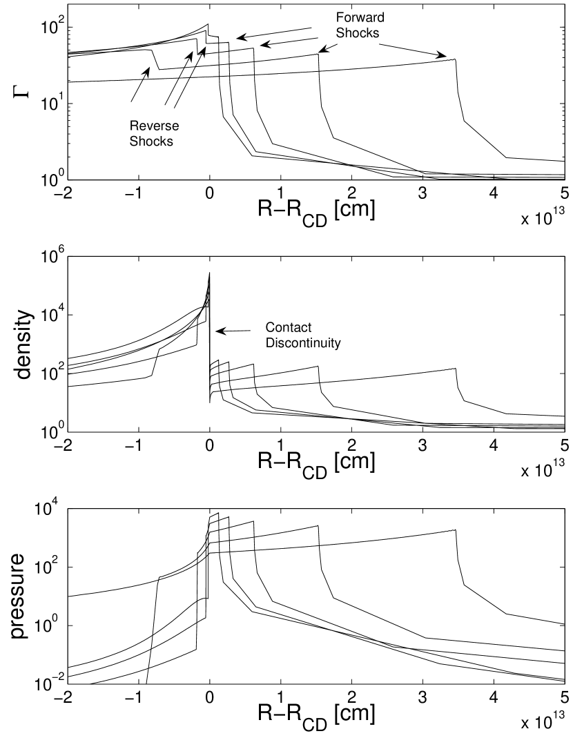
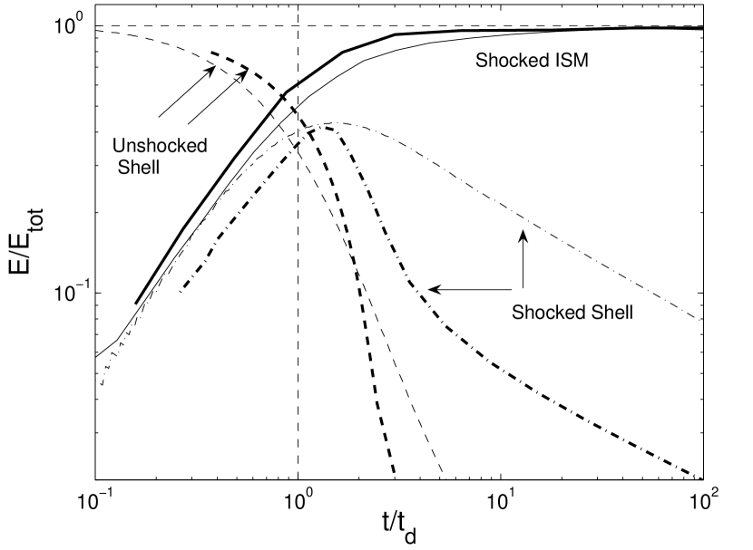
The interaction between the shell and the ISM is described by two shocks: a forward shock propagating into the ISM and a reverse shock propagating into the shell. Figure 3 shows the propagation of the shocks. Initially, the unshocked fireball shell has all the energy of the system. As the shell expands, the reverse shock decelerates the ejecta while the forward shock accelerates the ISM. The energy is transfered from the unshocked shell to the ISM via the shocks, finally the shocked ISM carries essentially all the energy of the system. In the intermediate stage, around the deceleration time sec, the shocked shell has comparable energy to the shocked ISM. The evolution of the energies in three regions, inside of the reverse shock (unshocked shell), between the reverse shock and the contact discontinuity (shocked shell), and between the contact discontinuity and the forward shock (shocked ISM) are shown in Figure 4. The observed times of photons from the reverse shock front, the contact discontinuity and the forward shock front are used to describe the evolution of the energies.
Even after the deceleration time, the reverse shocked shell (the thin dashed-dotted line) carries a significant fraction of the system energy for a long time, at and at . In the thin shell case, the reverse shock is Newtonian or sub-relativistic in the frame of the unshocked shell (the deceleration by the reverse shock is not significant as we can see in the top panel of figure 3). It does not heat the shocked region well. The reverse shocked region is already cold at the shock crossing time (the deceleration time), and the shocked shell carries the energy mainly in the form of the kinetic energy . Assuming a power-law decay , we obtain for (Kobayashi & Sari 2000).
This slow energy transfer should lead to the round-off of an afterglow peak. To evaluate the afterglow light curve, we consider here a simple case in which the energy of the magnetic field remains a constant fraction of the internal energy . The electron random Lorentz factor evolves as after the shock heating where and are the pressure and density of a fluid element. The typical synchrotron frequency in the observer frame is . Since a relativistic shock totally ionizes material which it crosses, the total number of electrons in a fluid element (mesh cell) is where is a cell width in the lab frame. The spectral power at the typical frequency from a cell is given by . Assuming a power-law distribution of the electron random Lorentz factor with index , the observed flux is
| (5) |
where we have assumed that the observational band is located between the typical frequency and the cooling frequency . In early afterglow phase, with the typical parameters, X-ray and optical band satisfy this condition 444 For the typical microscopic parameters and , the numerical results shown in this paper actually satisfy this condition in the time ranges of the plots ( Figs 5 and 7 ) where and are the fractions of shock energy given to magnetic field and electrons at a shock, respectively. Choosing a larger could produce an additional break at s especially in X-ray light curves due to the passage of the forward-shock cooling frequency in X-ray band. However, the steepening is small =1/4 and it happens well after the deceleration of the fireball. The cooling break does not affect our discussions about the onset of afterglows. for the forward shock and reverse shock emission, respectively. We evaluate the flux and observed time of photons from each shocked fluid element, and superimpose the emission to construct the forward and reverse shock light curves. The results are shown in figure 5. Although at later times the light curves approach the expected power-law decays (forward shock; the thick solid line) and (reverse shock; the thin solid line), the peaks are rounded as we expected.
At the deceleration time (and after that), the light crossing time of the forward shocked region is comparable to the observed time . To evaluate the effect of the thickness of the forward shocked region, we assume that all the shocked electrons emit photons at the forward shock front. The resulting light curve peaks at an earlier time 555 A peak time is given by the sum of a deceleration time and a fraction of the light crossing time of a shocked region. If all the shock energy is assumed to be radiated at the shock front, the emission should peak earlier. The analytic deceleration time is obtained based on a simple model, and it could have an error of a factor of a few. , but the shape around the peak itself is similar. We conclude that the round-off of the afterglow peak is mainly due to the slow energy transfer from a fireball shell to a blast wave.
The internal shock model requires a highly irregular outflow from the GRB central engine. Since the hydrodynamic interaction inside the flow smooths the velocity and pressure profiles, but not the density profile, fireball ejecta might have an irregular density profile at the deceleration time. Emission from the ejecta during a reverse shock crossing could reflect the light curve of the prompt emission produced by internal shocks (Nakar & Piran 2004). The peak time of the reverse shock emission also depends on the density profile. As a fireball expands, a reverse shock accelerates more and more electrons in the fireball while the Lorentz factor and pressure of the shocked region decreases. The balance determines the peak time. In the thin shell case, a reverse shock does not effectively decelerate the shell material that it crosses. This leads to large pressure gradient across the shocked region. The contribution of emission from the inner part of the shell becomes negligible, and the reverse shock emission peaks slightly before the shock crossing time (the thin solid line).
3.2 The Thick Shell Case
We consider the thick shell case in which a reverse shock becomes relativistic during the propagation. The initial condition is ergs, , cm, and cm-3. The fireball is decelerated around cm, which corresponds to the shock crossing time sec.
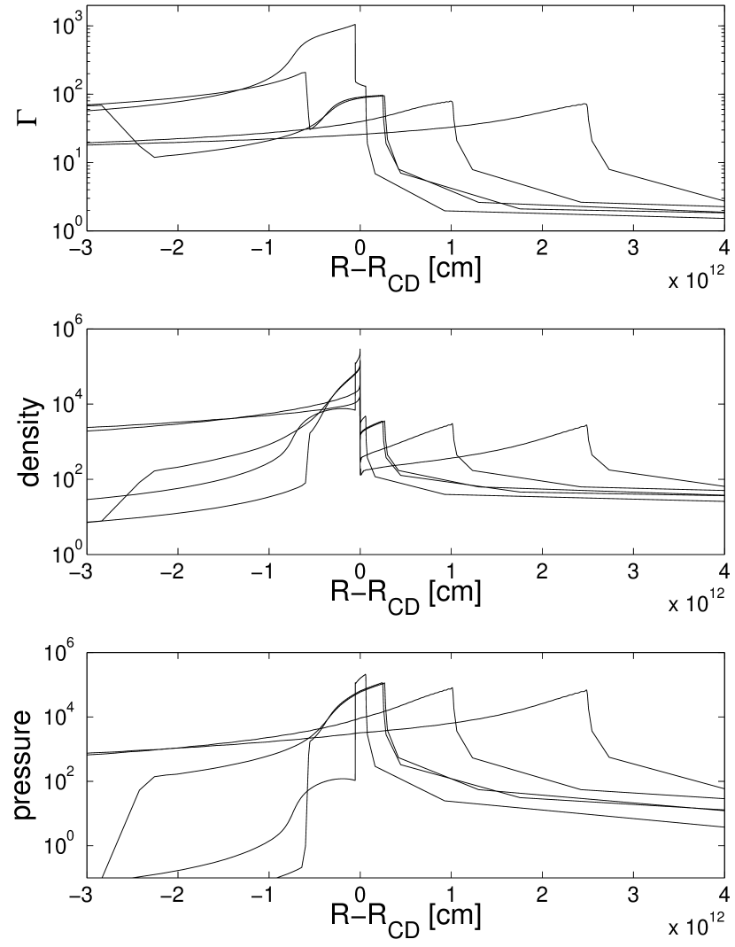
The energy transfer from the fireball to a blast wave is similar to that described in the thin shell case. At the shock crossing time, the forward-shocked ISM and reverse-shocked shell have comparable energies (the thick lines in figure 4). The main difference is that in the thick shell case the shocked shell carries the energy in the form of the internal energy, instead of the kinetic energy, because the reverse shock significantly decelerate the shell. Figure 6 depicts the profiles of , and . When the reverse shock crosses the shell with a width of , a rarefaction wave begins to propagate towards the contact discontinuity, and it quickly transfers the shell’s internal energy to the shocked ISM in a timescale comparable to the deceleration time (the shock crossing time). The steep decay of the shocked shell energy right after the peak (the thick dashed-dotted line) is due to the rarefaction wave propagation. Since for our parameters the reverse shock is mildly relativistic in the frame of the unshocked shell several (Sari & Piran 1995), the shocked shell becomes cold after the propagation, and the energy of the shocked shell begins to decay in the same rate as the thin shell does.
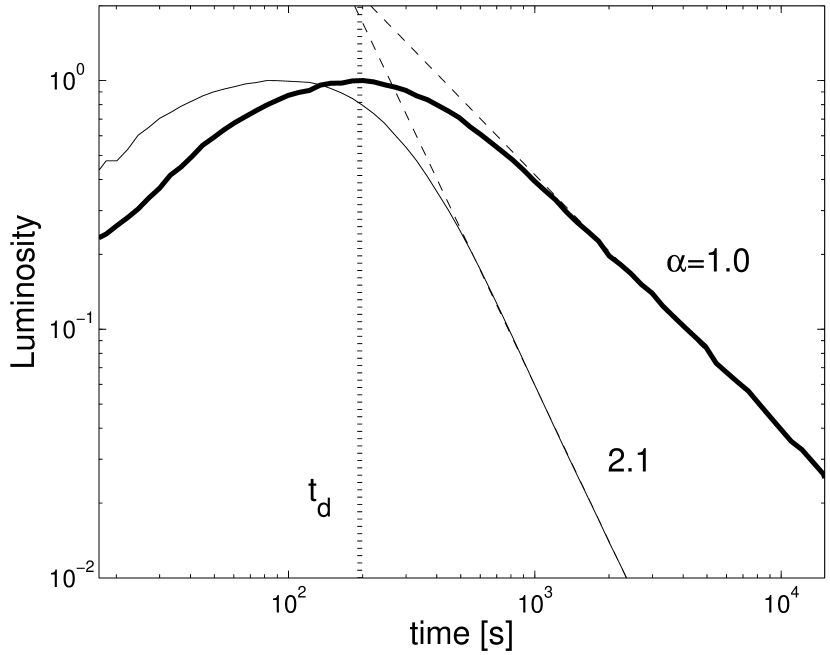
In the thick shell case, the energy of a shocked shell is swiftly relayed to a forward shock by a rarefaction wave. A broken power-law and describes the evolution of the forward shock well. The round-off of an afterglow peak is expected to be small. Using eq. (5) and numerical results, we evaluate the light curves of the forward shock and reverse shock emission, which are shown in figure 7. Initially the luminosity of the both shocked region slowly increases as (Kobayashi 2000), and they peak around the shock crossing time. The forward shock light curve (the thick solid curve) is slightly steeper right after the peak compared to at late times. Although the decay is described well by a single power law if the reference time is set at the middle between the GRB trigger and the afterglow peak as we discussed in section 2, measuring times from the GRB trigger also provides a reasonable estimate for the afterglow decay. The reverse shock emission (the thick dashed curve) drops sharply during the rarefaction wave propagation. The high latitude (off-axis) emission could contribute to the early flux (Kumar & Panaitescu 2000). The numerical fireball shell has a long tail in the density profile, and the shocked tail contributes to the light curve at late times. The emission from the outer part containing 80% of the shell mass gives a steeper light curve (the thin solid curve).
4 Inhomogeneous Fireball
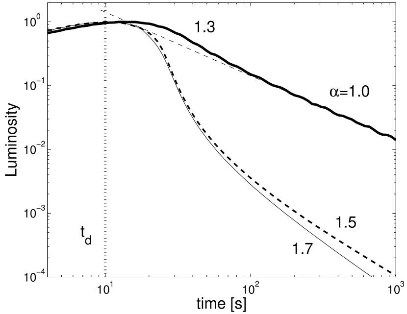
If a burst has a precursor, we might need a shift of the reference time to a later time. A simple example is that a precursor with a negligible energy is followed by the main component. The quiescent period could be due to a dormant period in the central engine or due to the property of the outflow (e.g. homogeneous outflow in which prompt gamma-rays are not produced by internal shocks). In the former case, should be set at the explosion time of the main component. If the separation between the precursor and the main component is much larger than the deceleration time of the main component, measuring times from the precursor introduces an artificial steeping in the early afterglow. Assuming a precursor and measuring times from it, we have replotted figures 5 and 7. If the precursor is located at sec or sec before the main component, the decay index of the early forward shock emission could be overestimated as or in the thin shell case. In the thick shell case, and lead to steep decay indexes of and , respectively. Since afterglow light curves are usually plotted with setting at the GRB trigger time, precursors, although they might be energetically small, need to be strong enough to trigger GRB detectors (e.g. BAT) in order to cause an artificial steep decay.
4.1 Case Studies
X-ray flares were originally reported from BeppoSAX observations, GRB 011121 and GRB 011211 (Piro et al 2005). GRB 011121 was the second-brightest GRB observed by BeppoSAX in gamma-rays (after GRB 990123) and in X-rays (after GRB 010222). The fluence in the 2-700 keV range corresponds to an isotropic energy of ergs at the redshift of the burst . The gamma-ray light curve shows a main peak starting at sec and ending at sec with minor substructures. An X-ray flare took place at sec. The fluence of GRB 011211 in the 2-700 keV range gives an isotropic energy of ergs at the redshift of the burst . The gamma-ray prompt emission has a long duration sec, and an X-ray flare is detected from 600 to 700 sec. In the source frame, the two flares occurred at a similar time sec and they have a width sec (see Piro et al. 2005 and references therein for the basic parameters of these bursts).
Since the decay part of the X-ray flares and the following shallower part are described with a single power-law when the time is measured starting from the flare peak, the flares were suggested as the beginning of the afterglow caused by a thick shell (Piro et al. 2005). The thick shell interpretation requires a long energy release from the central engine. The burst should be long and extend all the way to the flare peak. However, the observed prompt emission ended well before the onset of the flares. In order to suggest the thick shell case, one must assume that the efficiency of conversion into gamma-ray varies dramatically with time. Furthermore, the engine should release most fireball energy at the last moment (major reenergization at the flare), because measuring times from the GRB trigger does not lead to an overestimate of the decay index even in the thick shell case, as long as the shell is homogeneous.
In principle, the low conversion efficiency could originate from (1) a small Lorentz factor of late ejecta which does not allow gamma-ray radiation or (2) a small dispersion of the Lorentz factor of late ejecta in the internal shock scenario. The critical Lorentz factor is given by where in the cgs unit and . In the scenario (1), the low Lorentz factor condition requires that the last energetic ejecta with an energy ergs and a width sec should be in the thin shell regime. The deceleration observed time sec becomes much larger than the width of the flares sec, and one finds that the scenario (1) is inconsistent 666 In the afterglow modeling of this thin shell case, measuring times from the GRB trigger does not cause an early steep decay, because the separation between the beginning of the prompt emission and the flare sec is smaller than the deceleration time sec. As we have shown at the beginning of this section, a significant artificial steepening happens only when the ratio is larger than ..
To examine the scenario (2), we consider an inhomogeneous shell (two components) expanding into ISM. Corresponding to the major energy release from the central engine at the last moment, the inner edge of the shell with a width sec is assumed to have an energy larger than the energy ergs in the preceding outer part with a width sec. The Lorentz factors of the two components at the end of the internal shock phase are the same value of . Both components should be in the thick shell regime, otherwise the deceleration time of the shell becomes larger than the flare occurrence time sec. The deceleration radius of the shell should be larger than the radius at which a reverse shock crosses the outer component where . The separation at the deceleration time between the gamma-ray front and the reference BM blast wave satisfies . The separation at that time between the gamma-ray front and the fireball is where we have assumed the fireball evolution before the deceleration. Note that a broke power law description of around the deceleration radius is a good approximation in the thick shell case. Then, we obtain . The precursor discussion at the beginning of this section corresponds to the two component model with . We can show that the separation ratio at the deceleration time is in this case. Since replotting figure 7 we have found that to produce an early steep decay, in the scenario (2) should be at least ten times larger than . This requires a large energy budget for the central engine ergs. Even in the limit of , the small ratio does not lead to a very steep decay of . Therefore, we conclude that even an inhomogeneous fireball can not produce X-ray flares in early afterglow via external shock emission process.
5 Conclusions
We have studied the reference time for the afterglow modeling. Although measuring times from the beginning of the prompt emission (GRB trigger) might cause a slight overestimate of the early afterglow slope in the thick shell case. This choice of gives a reasonable approximation, and it does not induce a very steep decay () like the early steep decay or X-ray flares in the canonical Swift X-ray light curve.
The leading model to explain the rapid decay and flares in early X-ray afterglow is the internal shock emission. A clear, testable prediction of this model is that the temporal decay index of the tail part should be related to the spectral index by an equation (Kumar & Panaitescu 2000). When evaluating the emission decay in the internal shock model, an important difference is that the GRB trigger time is no longer special. The reference time should correspond to the onset of each particular spike in the prompt emission or in afterglow (Kobayashi et al. 1997; Zhang et al. 2006a; Nousek et al. 2006; Fan & Wei 2005). Every time when the central engine is re-stared to eject sub-shells, the reference time should be re-set to the reactivation time of the engine. Although O’Brien et al. (2006) have found that appears to be largely independent of when the BAT trigger time is used as , Liang et al (2006) have shown that the relation is more or less satisfied in most cases if is set near the beginning of rising segment of the last pulse of the prompt emission or a corresponding X-ray flare, and if the underlying forward shock emission component is subtracted. Swift observations support the internal shock model.
The self-consistent internal shock interpretation should be more favorable than the beginning-of-the-afterglow interpretation. The latter can not explain multiple X-ray flares in a single event. Such behavior is observed in many Swift bursts (Burrows et al. 2005; Falcone et al. 2006; Romano et al. 2006; O’Brien et al 2006). Usually X-ray flux already begins to decay before X-ray flares appear, and it suggests that the onset of afterglow is prior to the flares. If a large amount of energy is impulsively injected to a fireball during the deceleration, might be re-set to the injection time. However, an afterglow baseline also should shift after a flare (energy injection). This clearly contradicts with observations in which after a flare peak, afteglow decays back to its pre-flare flux level. We can not explain X-ray flares by the shift of associated with large energy injections.
Swift discovered that a large fraction of X-ray afterglows have a slow decay phase, and it is suggested that energy injection into a blast wave takes place several hundred seconds after the burst. This implies that right after the burst the kinetic energy of a blast wave is very low and in turn the efficiency of internal shock process is extremely high (Zhang et al. 2006a; Nousek et al. 2006; Ioka et al. 2005; Granot, Königl & Piran 2006; Zhang et al.2006b; however see also Fan & Piran 2006). The round-off forward shock peak in the thin shell case might be a good candidate for the shallow decay phase. However, if we interpret the observed shallow decay as the round-shape of the deceleration phase, the model light curve is shallower than some of the observed ones. It may be because the observed curve is the combination of this round phase and the rapid decay from the GRB tail emission (high latitude). Equalizing the deceleration time and the shallow phase timescale we obtain the initial Lorentz factor where the time dilation effect is taken into account .
For a wind environment, we can discuss the issue in a very similar way. The Lorentz factor of a shocked shell is constant in both of the thin and thick shell cases during the shock crossing, while the BM blast wave decelerates as (Kobayashi & Zhang 2003). The separations are comparable at the deceleration time. Measuring times from the beginning of the prompt phase should be a good approximation for events in a wind environment also. Since most bursts in a wind environment fall in the thick shell case (Kobayashi, Mészáros & Zhang 2004), and since the deceleration time is comparable to GRB duration in the thick shell case, another process (e.g. refreshed shocks) rather than the afterglow peak is necessary to explain the shallow decay phase.
We thank Luigi Piro for useful discussion. This work is supported by NASA NNG05GB67G and NNG06GH62G.
References
- (1) Barthelmy,S.D. et al. 2005, Nature, 438, 994
- (2) Blandford,R.D.& McKee,C.F. 1976, Phys,Fluids, 19, 1130
- (3) Burrows,D. et al. 2005, Science, 309, 1833
- (4) Chincarini,G. et al. 2005, Submitted to ApJ, astro-ph/0506453
- (5) Falcone,A.D. et al. 2006, ApJ, 641, 1010
- (6) Fan,Y.& Piran,T. 2006, MNRAS, 369, 197
- (7) Fan,Y.& Wei,D.M. 2005, MNRAS, 364, L42
- (8) Granot, J.,Königl,A.& Piran,T. 2006, MNRAS, 370, 1946
- (9) Ioka,K.,Kobayashi,S.&Zhang,B.2005, ApJ, 631, 429
- (10) Ioka,K.,Toma,K.,Yamazaki,R.&Nakamura,T.2005, A&A in press, astro-ph/0511749
- (11) Kobayashi,S. 2000, ApJ, 545, 807
- (12) Kobayashi,S.,Mészáros ,P.&Zhang,B. 2004, ApJ, 601, L13
- (13) Kobayashi,S.,Piran,T.&Sari,R. 1997, ApJ, 490, 92
- (14) Kobayashi,S.,Piran,T.&Sari,R. 1999, ApJ, 513, 669
- (15) Kobayashi,S.& Sari,R. 2000, ApJ, 542, 819
- (16) Kobayashi,S. &Zhang,B. 2003, ApJ, 597, 455
- (17) Kumar, P. & Panaitescu,A. 2000, ApJ, 541, L51
- (18) Lazzati,D. & Begelman,M.C. 2006, ApJ, 641, 972
- (19) Lazzati,D.,Ramirez-Ruiz,E. & Ghisellini,G. 2001, A&A, 379, L39
- (20) Liang,E.W. et al. 2006, ApJ, 646, 351
- (21) Martí,J.M.. & Müller,E. 1999, Living Rev. Relativity, 2, 3
- (22) Nakar,E. & Piran,T. 2004, MNRAS, 353, 647
- (23) Nousek,J.A. et al. 2006, ApJ, 642, 389
- (24) O’Brien, P.T. et al. 2006, ApJ, 647, 1213
- (25) Piro et al. 2005, ApJ, 623, 314
- (26) Quimby,R.M. et al. 2006, ApJ, 640, 402
- (27) Romano,P. et al. 2006, A&A, 450, 59
- (28) Sari,R. 1997, ApJ, 489, L37
- (29) Sari,R.& Piran,T.1995, ApJ, 455, L143
- (30) Sari,R.,Piran,T.& Narayan,R. 1998, ApJ, 497, L17
- (31) Tagliaferri,G. et al. 2005, Nature, 436, 985
- (32) Waxman,E. 1997, ApJ, 491, L19
- (33) Zhang,B. et al. 2006a, ApJ, 642, 354
- (34) Zhang,B. et al. 2006b, submitted to ApJ