Observations of the Crab Nebula with H.E.S.S.
Abstract
Context. The Crab nebula was observed with the H.E.S.S. stereoscopic Cherenkov-telescope array between October 2003 and January 2005 for a total of 22.9 hours (after data quality selection). This period of time partly overlapped with the commissioning phase of the experiment; observations were made with three operational telescopes in late 2003 and with the complete 4 telescope array in January – February 2004 and October 2004 – January 2005.
Aims. Observations of the Crab nebula are discussed and used as an example to detail the flux and spectral analysis procedures of H.E.S.S.. The results are used to evaluate the systematic uncertainties in H.E.S.S. flux measurements.
Methods. The Crab nebula data are analysed using standard H.E.S.S. analysis procedures, which are described in detail. The flux and spectrum of -rays from the source are calculated on run-by-run and monthly time-scales, and a correction is applied for long-term variations in the detector sensitivity. Comparisons of the measured flux and spectrum over the observation period, along with the results from a number of different analysis procedures are used to estimate systematic uncertainties in the measurements.
Results. The data, taken at a range of zenith angles between 45∘ and 65∘, show a clear signal with over 7500 excess events. The energy spectrum is found to follow a power law with an exponential cutoff, with photon index and cutoff energy between 440 GeV and 40 TeV. The observed integral flux above 1 TeV is . The estimated systematic error on the flux measurement is estimated to be 20%, while the estimated systematic error on the spectral slope is 0.1.
Key Words.:
Gamma rays: observations – ISM: individual objects: Crab nebula – ISM: plerions1 Introduction
The Crab supernova remnant (SNR) is an exceptionally well studied object, with extensive observations of the system existing across the entire accessible spectrum. At a distance of 2000 parsecs, with an age of 950 years, it is a prototypical centre-filled SNR, or plerion, as defined by Weiler & Panagia (1980). Within the supernova remnant lies the Crab pulsar, with a rotational period of 33 ms and a spin-down luminosity of . This energy source powers a surrounding synchrotron nebula, and polarization measurements exist from radio to hard X-ray wavelengths (Wilson, 1972), indicating the non-thermal origin of the radiation detected. The total energy available from the pulsar to power the system is of the order of ergs. This is believed to be the power source for production of very high energy (VHE) -rays.
The rotational energy of the pulsar is thought to be mostly carried away by a relativistic wind of electrons and positrons. Interaction of this wind with the surrounding medium causes a standing termination shock wave (Rees & Gunn, 1974; Kennel & Coroniti, 1984). Electron acceleration may be due to a Fermi-type process (Achterberg et al., 2001) or to driven reconnection of the alternating magnetic field at this termination shock (Coroniti, 1990; Michel, 1994). The interaction of accelerated electrons with ambient photon fields (in this case mostly synchrotron photons) can produce VHE -rays via the inverse Compton process.
The Crab nebula was discovered at VHE energies in 1989 (Weekes et al., 1989) and emission has been confirmed by a number of other experiments, (Goret et al., 1993; Baillon et al., 1993; Masterson et al., 1999; Aharonian et al., 2000; Smith et al., 2000; Atkins et al., 2003). Due the high flux from the source relative to other known TeV sources, and its expected flux stability, it is conventionally used as a standard reference source for VHE astronomy. At the latitude of the H.E.S.S. experiment the Crab nebula culminates at 45∘, so observations of this source must always be made at large zenith angles; the greater effective optical depth of the atmosphere increases the energy threshold and affects the sensitivity of the detector. As the size of the Crab nebula is small compared to the H.E.S.S. point-spread function, it may be treated as a point source for this analysis.
A detailed description of the H.E.S.S. detector is given here, along with a discussion of the principal sources of systematic error in the atmospheric-Cherenkov technique. The H.E.S.S. observations of the Crab nebula are then detailed, and used as an example in a discussion of the data calibration and analysis methods used in source reconstruction and flux and spectral measurements. The stability of the -ray flux and energy spectrum is measured using a number of analysis methods, and a correction for variations in the long-term optical efficiency of the detector is described. Using these results the systematic uncertainties on flux measurements with H.E.S.S. are quantified. The sensitivity of the detector for source analysis is also discussed. It should be noted that while the analysis presented here is generally used to analyse targets observed by H.E.S.S., other techniques are also used, e.g. Lemoine et al. (2006).
2 The H.E.S.S. Experiment
H.E.S.S. is situated in the Khomas highlands of Namibia (23∘ 16’18” South, 16∘ 30’00” East), at an elevation of 1800 metres above sea level. The four H.E.S.S. telescopes are placed in a square formation with a side length of 120 metres. This distance was optimised for maximum sensitivity at the planned energy threshold of 100 GeV.
2.1 The detectors
The H.E.S.S. telescopes are of steel construction, with altitude/azimuth mounts capable of precisely tracking any source from 0.0∘ to 89.9∘ in elevation, with a slew rate of 100∘ per minute (Bolz, 2004). The dishes have a Davies-Cotton style hexagonal arrangement (Davies & Cotton, 1957) with a flat-to-flat diameter of 13 m, composed of 382 round mirrors, each 60 cm in diameter. Thus the effective mirror surface area is . Further details of the optical structure are given by Bernlöhr et al. (2003). The mirrors are remotely adjustable under computer control, and a fully automated procedure is used, in conjunction with a CCD camera mounted in each dish, for optimal alignment onto the focal plane of each telescope camera, which is 15 m distant. Due to the rigidity of the dishes, this alignment is stable over time scales in excess of one year. The stability has been verified by regular monitoring of the optical point spread function. Details of the mirror alignment system and the optical point spread function are discussed by Cornils et al. (2003).
The H.E.S.S. cameras each consist of a hexagonal array of 960 Photonis XP2960 photo-multiplier tubes (PMTs). Each tube corresponds to an area of 0.16∘ in diameter on the sky, and is equipped with Winston cones to capture the light which would fall in between the PMTs, and also to limit the field of view of each PMT in order to minimise background light. The camera is of modular design, with the PMTs grouped in 60 drawers of 16 tubes each (Vincent et al., 2003), which contain the trigger and readout electronics for the tubes, as well as the high voltage (HV) supply, control and monitoring electronics. The total field of view of the detector is 5∘ in diameter.
The trigger system of the H.E.S.S. array consists of three levels. First, a single pixel trigger threshold is required, equivalent to 4 photo-electrons (p.e.) at the PMT cathode within an interval of 1.5 nanoseconds. Second, a coincidence of 3 triggered pixels is required within a sector - a square group of 64 pixels - in order to trigger a camera. Each camera has 38 overlapping sectors. Third, when the detector is operating in stereo mode, a coincidence of two telescopes triggering within a window of (normally) 80 nanoseconds is required. Only cameras which have individually triggered are read out in a stereo event. The stereo trigger system and the trigger behavior of the H.E.S.S. array is described by Funk et al. (2004).
During the first and second level trigger formation, the individual signals from each pixel are stored in two analogue ring sampler (ARS) circuits. A high gain and a low gain circuit are used to give optimal signal dynamic range. The signals captured by each tube are digitised in the drawer, before being collected by a central CPU in the camera and sent to the central data acquisition system (DAQ) by optical ethernet connection (Borgmeier et al., 2003).
The H.E.S.S. experiment commenced observations in June 2002 with the first telescope. The second telescope was installed in February 2003, the hardware level stereo coincidence trigger was added in July 2003. In the interim the two telescopes observed in parallel and an off-line coincidence was used for stereo analysis. The third telescope was installed in September. The full array was completed in December of 2003 and has been operational since then.
2.2 Systematic uncertainties
The imaging atmospheric-Cherenkov technique depends on a form of electromagnetic calorimetry to estimate the energy of observed particles. In order to accurately measure the energy of the primary particle which gives rise to an air shower, it is necessary to understand the relationship between the particle energy and the signal recorded in the cameras. Monte Carlo simulations of air showers in the atmosphere are used to predict the light yield in the detector, and thus the recorded signal, as a function of energy and shower position relative to the observer.
There are three main contributions to uncertainties in the measured air shower information, and thus the absolute flux calibration of the detector:
-
1.
The camera response. The single photo-electron response of each PMT varies strongly with the detector voltage and is measured using an LED system mounted in front of the camera. A second LED system mounted on each dish provides a uniform illumination across the camera and is used to correct for relative quantum efficiency variations of the PMTs, as well as in the reflectivity of the Winston cones in front of each PMT. The complete calibration of the H.E.S.S. telescope is described by Aharonian et al. (2004a).
-
2.
The optical response of the instrument, including the mirrors, Winston cones, shadowing by structural components of the system and the quantum efficiency of the photo-cathodes of the PMTs. This response can be measured by studying the Cherenkov light from single muons passing close to the telescope, assuming the camera response is well measured. The use of muons in monitoring the telescope efficiencies is detailed by Bolz (2004) and Leroy et al. (2004). The optical response of the instrument degrades over a timescale of years as, for example, the mirror reflectivity decreases. This decrease in optical response, relative to that used in the Monte Carlo simulations, is taken into account in estimating the flux from a -ray source. This is described in detail in section 3.4.
-
3.
The interactions of particles and light in the atmosphere. The atmosphere is the largest and least well understood component of a Cherenkov detector, being subject to variations in pressure, temperature and humidity. Two important effects of variability in the atmosphere are density profile variations, which affect directly the height of the shower maximum in the atmosphere and thus the intensity of the light seen at the telescope, and absorption of Cherenkov light in the atmosphere by clouds and dust, which leads directly to a reduction in the telescope trigger rates, and incorrect -ray energy reconstruction. These effects are discussed further by Bernlohr (2000). Atmospheric monitoring devices are used to understand the local conditions under which the data has been recorded; such measurements are discussed by Aye et al. (2005). Variations in the atmosphere can lead to rapid variability in the detector response, on a timescale of hours, so runs taken under variable conditions are rejected, as discussed in section 3.2.
3 Observations
| Data Set | Date | N | Z range | Offset | N | Obs. Time | Live-time | Mean System rate | |
|---|---|---|---|---|---|---|---|---|---|
| (∘) | (∘) | (∘) | (hours) | (hours) | (Hz) | ||||
| I | 10/’03 - 1/’04 | 3 | 45-55 | 46.6 | 0.5-1.5 | 12 | 5.3 | 4.8 | 179 |
| II | 1/2004 | 4 | 45-65 | 54.4 | 0.5-1.5 | 14 | 6.3 | 5.7 | 240 |
| III | 10/’04 - 1/’05 | 4 | 45-55 | 47.9 | 0.5-1.5 | 26 | 11.3 | 10.6 | 180 |
| Total | 45-65 | 50.2 | 0.5-1.5 | 52 | 22.9 | 21.1 | 196 |
3.1 The Crab data set
The observations of the Crab nebula discussed in this paper are summarised in Table 1. Data set I was taken between October 2003 and January 2004 with three telescopes, and 5.3 hours of data are included in this sample. These data range in zenith angles from 45∘ to 55∘. A further 6.3 hours (data set II) are included from data taken in January 2004 with the complete array of four telescopes, at a range of zenith angles from 45∘ to 65∘. Data set III includes 11.3 hours, taken between October 2004 and January of 2005, also with 4 telescopes. All observations were taken using a method (wobble mode) whereby the source is alternately offset by a small distance within the field of view, alternating between 28 minute runs in the positive and negative declination (or right ascension) directions (Fomin et al., 1994). This observation mode allows the other side of the field of view, which does not contain the source, to be used as a control region for estimation of the background level. The wobble offsets were varied from 0.5∘ to 1.5∘ for the data discussed here. The range of time over which the observations have been taken allows us to study the long-term stability of the H.E.S.S. system.
Observations of the Crab were also taken in 2002 with a single telescope, as discussed by Masterson et al. (2003). These are not included in this analysis, as the sensitivity is much lower than that in stereo mode, and the systematic uncertainties of single-telescope observations are greater than for stereo mode.
3.2 Data quality selection
Systematic effects on the measured flux and energy spectrum (as discussed in section 2.2) may be ameliorated by rejecting data recorded in non-optimal conditions. Although the Crab was observed for a total of nearly 45 hours, only 22.9 hours are included in this analysis. The remaining observations have been rejected as not meeting the run quality criteria. Some were made when the sky conditions were less than optimal; the presence of clouds or excessive dust in the atmosphere can lead to the absorption of Cherenkov light and thus fluctuations in the system trigger efficiency, causing systematic uncertainties in the measured -ray flux. Figure 1 shows the trigger rate as a function of time for two runs, one with a stable system trigger rate close to the predicted level for this zenith angle, the other exhibiting variability due to the presence of clouds.
Runs for which the mean trigger rate is less than 70% of the predicted value (as discussed by Funk et al. (2004)), or for which the rms variation in the trigger rate is above 10%, are rejected. As the Crab is mainly visible during the rainy season in Namibia when weather conditions are not optimal, the rejection rate for these data is not representative of all H.E.S.S. observations. The mean system rate is 240 Hz for the four telescope data and 180 Hz for the 3 telescope data.
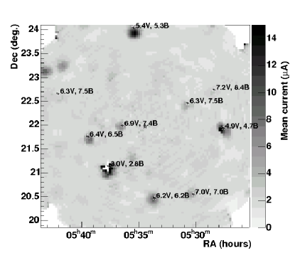
Quality checks are also routinely carried out in order to reject runs in which the array tracking system may not be functioning correctly, leading to errors in the reconstructed position of the source, and thus the flux. The nominal performance of the H.E.S.S. tracking system is discussed by Hofmann et al. (2003). The tracking errors reported from the DAQ are monitored and runs with rms deviations of more than 10 arcseconds in altitude or azimuth are rejected, in order to exclude runs in which the tracking system malfunctioned. However, no observations on the Crab in this study (and in general very few runs) have failed this test. As an independent check of the tracking quality the DC PMT currents (Aharonian et al., 2004a) are used to estimate the amount of light impingent on each pixel during every run as a function of time. A map is then made of the sky brightness in the field of view of each telescope. The positions of known stars are then correlated with this map, giving a measure of the pointing position of each telescope, independent of the tracking system and standard pointing corrections. A sample image for the region surrounding the Crab nebula is shown in Figure 2. Runs are rejected if the pointing deviation is greater than 0.1∘. Again no runs are found to have failed this test, which acts as an auxiliary check of the tracking system.
The presence of bright stars in the field of view may trigger the over-current protection of individual PMTs, causing them to be turned off. Over-current due to bright star images is predicted and the relevant PMTs are turned off in advance, for the duration of the star transit through the PMT. Occasionally other bright, transient light sources pass through the field of view of the telescopes. These are normally meteorites, however lightning, airplanes and satellites may also cause problems. The events cannot be predicted and thus trigger the over-current protection, causing the PMT to be turned off for the remainder of the run. The mean number of PMTs inactive during each run for this and other hardware related reasons is monitored, and telescopes with more than 10% of the PMTs missing at any one time are rejected from the analysis. The PMT quality cut only rejects occasional runs from each data set, and the mean number of pixels per telescope disabled during the Crab nebula observations is 66, with an rms of 7.
The observation time after run selection is corrected by taking into account the dead-time of the system, when the trigger is not sensitive to air showers. Estimation of the live-time (the time during an observation in which the telescope system is sensitive to triggers from the sky) is discussed by Funk et al. (2004). The total live-time for each data set is listed in Table 1. The systematic error on this estimation is less than 1%.
3.3 Photoelectron to pixel amplitude calibration
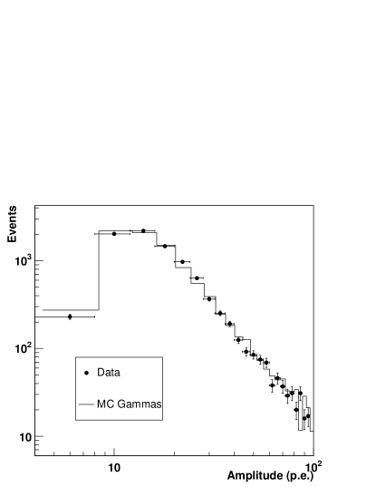
All of the sources of uncertainty discussed in section 2.2 affect the pixel intensities, and thus the energy reconstruction of each shower. The trigger efficiency and energy threshold are also affected, contributing to uncertainty in absolute flux measurements. Part of this effect, namely the camera response, is continuously calibrated using the LED system; the accuracy of this calibration system can be evaluated by comparing the reconstructed pixel intensities from Monte Carlo simulations of air showers with similar measurements on real data. Figure 3 compares the intensities in the pixel with the third highest signal amplitude, as seen in real data for all triggering events, with those from Monte Carlo simulations of protons (which comprise a large majority of events detected) at the same zenith angle. As the trigger requirement is 3 pixels above a certain amplitude, the amplitude distribution of the 3rd pixel shows the effective pixel trigger level of each telescope. The peak in the distribution is determined by the trigger threshold of the telescope and the energy spectrum of the simulated and real events. It can be seen that the Monte Carlo simulations reproduce well the data (/dof= 15.5/23).
3.4 Optical efficiency correction
The optical efficiencies of the H.E.S.S. telescopes change over time, probable causes include degradation in the mirror reflectivity. This effect happens on a timescale of years and can be monitored using images of local muons in the field of view, for which the light yield can be predicted, as discussed in section 2.2.
The effect manifests itself as a reduction in the image intensity for each event, compared to the intensity expected from Monte Carlo simulations. This causes a shift in the absolute energy scale of the detector, as events are reconstructed with energies which are too low. This effect is corrected by incorporating a scaling factor into the energy estimation for each event. The image intensity used in the energy estimation is scaled by the ratio of the mean optical efficiency (over the telescopes) for the run () to the mean optical efficiency as derived from the Monte Carlo simulations (). The corrected energy is then derived from this scaled image intensity in the standard manner. The distribution of the relative optical efficiency () for the runs included in this analysis is shown in Figure 4. The application of the optical efficiency correction in flux estimation is discussed further in section 6.3.

4 Analysis
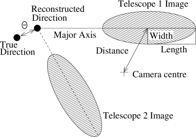
After a set of images of an air shower has been recorded, they are processed to measure Hillas parameters based on the second moments of the image (Hillas, 1985). These parameters are then used for event selection and reconstruction. A diagram illustrating the parameter definitions is shown in Figure 5.
4.1 Image cleaning and moment analysis
The first step in the moment analysis procedure is image cleaning. This is required in order to select only the pixels containing Cherenkov light in an image. Other pixels, which contain mainly night sky background (NSB) light are not used in the analysis. Images are cleaned using a two-level filter, requiring pixels in the image to be above a lower threshold of 5 p.e. and to have a neighbour above 10 p.e., and vice versa. Cleaning thresholds of 4 p.e. and 7 p.e. have also been shown to work satisfactorily, but may be more sensitive to uncertainties due to NSB light variations. This method selects spatially correlated features in the image, which correspond to air shower Cherenkov light. This method tends to smooth out shower fluctuations in a simple and repeatable manner.
After image cleaning, an image of a -ray shower approximates a narrow elliptical shape, while images of background hadronic events are wider and more uneven. The Hillas parameters are then calculated for each cleaned image; these parameters are the basis for event selection. The total amplitude of the image after cleaning is also calculated, along with the mean position of the image in the camera, which corresponds to the centroid of the ellipse.
4.2 Stereo reconstruction
The arrival direction of each event is reconstructed by tracing the projected direction of the shower in the field of view (which corresponds to the major axis of the image) to the point of origin of the particle. For stereo observations it is possible to intersect the major axes of the shower images in multiple cameras, providing a simple geometric method of accurately measuring the shower direction; more details, including methods to further improve the reconstruction accuracy are given by Hofmann et al. (1999), method I from that paper is used here. Images are only used in the stereo reconstruction if they pass the selection cuts on distance (to avoid camera-edge effects) and image intensity. If less than two telescope images pass these cuts the event is rejected.
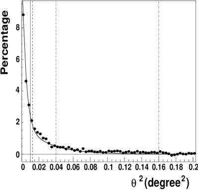
Figure 6 shows the excess distribution of for data sets I-III, including events with two, three and four telescopes; is defined in Figure 5, it is the angular offset between the reconstructed shower direction and the true direction of the Crab nebula. The distribution of reconstructed shower directions is usually expressed in units of , as this ensures a constant solid angle on the sky per bin. The value of the cut on reconstructed shower direction is thus given in units of in Table 2 for various sets of selection cuts, and plotted in Figure 6. A strong excess is seen close to zero, corresponding to events coming from the direction of the Crab nebula. This distribution defines the accuracy in the reconstructed arrival directions for -ray events from a point source and is described by the point spread function (PSF). This function can be approximated by the sum of two, one-dimensional Gaussian functions:
| (1) |
This function is fitted to the distribution for simulated Monte Carlo -rays. For simulations at 50∘ zenith angle the standard deviation parameters and are 0.046∘ and 0.12∘ respectively. The relative amplitude of the second Gaussian, Arel is 0.15, while the absolute amplitude (A) is proportional to the number of events in the fit. The 68% containment radius for 50∘ zenith angle is 0.12∘, while that for 10∘ zenith angle is 0.10∘. The point-spread function is shown in Figure 6 with the amplitude parameter (A) fit to the Crab nebula data. The /dof of this fit is .
The position of the centre of the Cherenkov light pool, which corresponds to the projected impact point of the original particle track on the ground, can also be reconstructed by intersecting shower axes, projected into the plane perpendicular to the system observing direction. It is vital to reconstruct this position in order to accurately measure the amount of light originally emitted by the shower and thus the shower energy. The rms error on the reconstructed impact parameter, which is the projected distance of the extrapolated shower track to a telescope, for Monte Carlo simulations is less than 10 metres for events falling within 200 metres of the centre of the array.
4.3 Scaled parameter analysis
The mean scaled width method, similar to that used by the HEGRA collaboration (Daum et al., 1997), is used to classify images as either -ray like or hadron like, in order to reject non -ray background events. The main difference to the HEGRA method is in the definition of the scaled parameter itself, in the HEGRA case this is defined as . A lookup table is used to predict the mean width and length for a -ray as a function of the amplitude of the shower image in the camera and impact parameter. Then the value for a particular event (p) can be compared with the expected value according to the formula:
| (2) |
The mean value and the scatter for an event vary with the image amplitude and impact distance, as well as the zenith angle. Lookup tables are generated for 13 zenith angles (Z) from 0∘ to 70∘, based on Monte Carlo simulations. The true impact parameter of the simulated shower is used in filling the table.
When analysing real data, the reconstructed impact parameter is used along with the image amplitude for each telescope image to find and in the lookup table. Linear interpolation (in ) between the two nearest simulated values is then done to find the correct value for a particular observation zenith angle. The mean reduced scaled width (MRSW) and the mean reduced scaled length (MRSL) are then calculated by averaging over the telescope images passing the image amplitude selection cut for each event: .
Figure 7 (a) shows a comparison between the MRSW from Monte Carlo simulations of protons and -rays and from real data at a zenith angle of 50∘. It can be seen that the data (before selection cuts) correspond well to Monte Carlo simulated protons, as expected, while there is good separation between the data and Monte Carlo simulated -rays, which are chosen to have a photon index () of 2.59, similar to that previously measured for the Crab nebula (Aharonian et al., 2000).
4.4 Selection cuts
Selection cuts on the mean scaled parameters, image intensity and are simultaneously optimized to maximise the detection significance (, as defined by Li & Ma (1983)) for sources with typical fluxes and energy spectra. The optimisation population consists of a mixture of -ray simulations (selected to give the desired flux and spectrum for optimisation) and real background data. In the presence of background, the significance achieved for a given source increases with the square root of the observation time; instrument performance is therefore characterised by . The optimised cuts yield the maximum for a source of that type. It should be noted that the optimum selection cuts in any analysis depend on the energy spectrum of the Monte Carlo simulations used in the optimisation procedure, and it may be necessary to optimise selection criteria separately for much harder or much softer energy spectra. As a rule this is not done however in source searches, in order to preserve the a priori nature of the analysis. The background data used in the optimisation is then not further used, in order to avoid the possibility of optimising on background fluctuations and compromising the statistical independence of the results. The selection cuts are summarized in Table 2. A number of alternative sets of cuts are presented here, which are used for analysis of H.E.S.S. sources. It will be shown that the reconstructed flux and spectrum of the Crab are consistent for these various selection criteria.
The standard set of selection cuts has been optimised to give the maximum for a flux 10% of the Crab (standard cuts), with a similar spectrum. The Hard cuts are optimised for a source with a flux 1% of the Crab flux, and a of 2.0. These cuts give a higher significance for weak, hard spectrum sources, at the expense of energy threshold and cut efficiency. The hard cuts are also useful as they reduce the systematic uncertainties in sky-map reconstruction by reducing the numbers of background events, relative to the signal. They also give a narrower PSF than the standard cuts, as the higher intensity cut selects better reconstructed events. A set of Loose cuts have been also optimised to give the maximum significance for a strong source, similar to the Crab, and a of 3.0. The lower intensity cut here reduces the energy threshold of the analysis relative to the standard cut, and the fraction events passing the cuts is higher. When conducting source searches, the standard cuts are always used unless there is an a priori reason to expect a very hard or very soft spectrum from the source.
For analysis of large extended sources the cut on is usually set to be larger than the extension of the source, so that effectively all -rays from the source pass this cut. In order to demonstrate the effect of this strategy, a version of the standard cuts is described, with the cut set to a much larger value. These are referred to as extended cuts for the purposes of this paper. It should be emphasised that only the standard selection cuts are used in searches for point sources, extended source searches are carried out using an a priori cut suited to the source size, and trials are taken into account when testing multiple source extensions.
Figure 7 shows the distributions of MRSW, after standard selection cuts and background subtraction (see following section), for real data and simulations (with the same mean zenith angle). The cut on MRSW is not applied for this plot. The standard MRSW selection cuts are indicated, it can be seen that the cuts select -ray-like events. The small shift between the data and Monte Carlo simulations seen in this plot is due to differences in the optical efficiency; simulations with reduced efficiency (as in Figure 4) agree well with the data. It can be seen that this shift has a negligible effect on the efficiency of the scaled parameter cuts.
| Configuration | MRSL | MRSL | MRSW | MRSW | Image Amp. | Distance | |
|---|---|---|---|---|---|---|---|
| Min. | Max. | Min. | Max. | Max. | Min. | Max. | |
| (degrees2) | (p.e.) | (∘) | |||||
| Standard | -2.0 | 2.0 | -2.0 | 0.9 | 0.0125 | 80 | 2.0 |
| Hard | -2.0 | 2.0 | -2.0 | 0.7 | 0.01 | 200 | 2.0 |
| Loose | -2.0 | 2.0 | -2.0 | 1.2 | 0.04 | 40 | 2.0 |
| Extended | -2.0 | 2.0 | -2.0 | 0.9 | 0.16 | 80 | 2.0 |
5 Signal extraction and background estimation
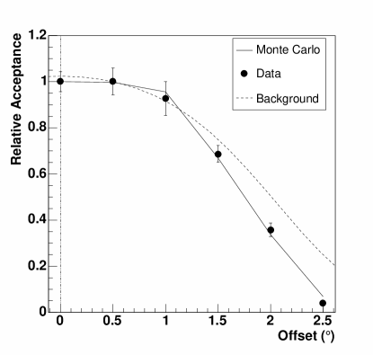
When estimating the flux of -rays from a particular direction in the sky it is necessary to estimate the background level, due to non -ray events with directions reconstructed close to the source direction. The significance of the excess after background subtraction is then determined using the likelihood ratio method described by Li & Ma (1983). For the purpose of background estimation the distribution of background events is usually assumed to be azimuthally symmetric within the camera field of view. However, zenith angle dependent effects or variations in the NSB level across the field of view may introduce non-radial variations in the background level. A radial profile of the relative rate of background events passing shape cuts (the background acceptance) in the field of view is shown in Figure 8 (dashed line). For comparison, a number of test observations (duration 30 minutes each) were made at a range of offsets from 0∘ to 2.5∘ on the Crab nebula. It can be seen that the relative rate of excess -ray events passing cuts (points) follow the background acceptance closely out to 1.5∘ offset in the camera. The Monte Carlo predicted -ray rate for this zenith angle is also shown (solid line), this is described in section 6.3.
When estimating the background, first the reconstructed shower direction for each -like event (i.e. an event that passed the shape cuts) is filled in a two dimensional histogram (so-called raw sky-map). The on signal for a given point in the sky is determined by selecting events within a circle around that point with radius . Two techniques are used to derive estimates of the background level within this region of the field of view, and are described below.
5.1 Reflected background model
The simplest background estimation technique uses the signal at a single position in the raw sky-map, offset in the opposite direction relative to the centre of the field of view, to estimate the background. This technique is used in the standard wobble observation mode (described in section 3). However, it suffers from relatively low statistics in the measurement of the background level due to the choice of a single reflected background position, as well as possible systematic effects caused by local inhomogeneities at the background position.
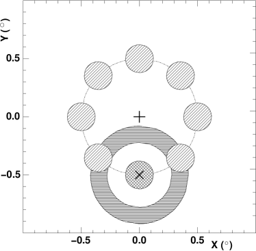
The generalised reflected background technique, which is also suitable for wobble mode, uses a number of background regions equidistant from the observation position, as illustrated in Figure 9. The combined events from these positions are used to estimate the background at the on position, scaled by the relative area of the on and off regions. In the case of a larger on integration region the number of background regions is reduced to eliminate overlapping. The normalisation, , is the ratio of the solid angles of the on and off regions. As the off positions are the same distance from the centre of the field of view as the on position, correction for the relative radial background acceptance of the detector is not required. However, this method cannot be used for positions closer to the centre of the field of view than the radius of the on region, as the background positions would overlap with the source position. As all of the data described here is taken in wobble mode, this method is used in this analysis for flux and spectral measurements.
The reflected-background method may also be susceptible to systematic effects caused by non-radial variations in the acceptance, especially for large offset positions in the field of view. Non-radial effects are strongest for data with only two telescopes, where the trigger efficiency can vary with the azimuth direction of the shower impact point on the ground relative to the telescope positions. This could be corrected by applying a small non-radial correction term across the field of view. This correction has not been applied in the analysis described here. However, in order to minimise systematic effects due to non-radial acceptance variations, the direction of the wobble offset is generally alternated run by run on either side of the target position.
5.2 Ring-background model
The ring-background technique determines the background for each position in the field of view using the background rate contained in a ring around that position (Pühlhofer et al., 2003). The internal and external radii of the ring are here chosen such that the ratio of the areas of the off to on regions is close to 7, which makes for a convenient compromise between area within the ring and distance from the on position. The inner ring radius is chosen to be significantly larger than the on region, in order to avoid signal leakage into the off region. The normalisation () is given by the area ratio modified by a weight factor to account for the radial background acceptance in the camera. The ring around the on position is illustrated in Figure 9. When estimating the background for a test position close to a known source like the Crab nebula, the source position is cut out of the background ring in order to avoid signal pollution in the off region for the test position. This method has the advantage of allowing background estimation for all positions in the field of view. However, since the number of events at positions surrounding the source is used to estimate the background in the direction of the source, it is most suitable for sources with an small angular extent relative to the field of view of the detector. Figure 10(a) shows an excess map of the sky in the vicinity of the Crab nebula, after background subtraction. Figure 10(b) shows the distribution of significance of the excesses in each bin in the sky map. It can be seen that the significance is distributed normally in the off source regions of the map (filled circles), while the region close to the Crab nebula (open circles) shows a significant excess.
The ring-background method is less suitable for spectral analysis of sources than the reflected method as the background acceptance may not be constant as a function of energy, thus the background level may not be correctly estimated for the entire energy range of the spectral analysis. Thus this method is not used for the main spectral and flux analysis in this paper, however results are derived using this method for comparison purposes.
6 Energy reconstruction and effective areas
6.1 Energy reconstruction
The energy of the primary particle of a -ray shower is estimated for each telescope as a function of the image amplitude and impact parameter using a lookup table. The lookup table contains the mean energy for Monte Carlo -ray simulations as a function of total image amplitude and the simulated true impact parameter. As for the scaled parameters, the lookup tables are created for a number of zenith angles and the resulting energy is estimated by linear interpolation in , and averaged over the triggered telescopes for each event. Events with relative error in the reconstructed impact parameter greater than 25% are not used in the lookup table creation, in order to reject poorly reconstructed events, which may bias the lookup table. Events with a distance greater than 2∘ from the centre of the field of view are also rejected.
In the case where no estimate is available in the lookup table for a particular event, due to a lack of Monte Carlo statistics at that combination of impact distance and total amplitude, an alternative lookup is used with coarser impact distance binning. This occurs on average for 0.3% of events. In the case where the optical correction is applied, the energy is estimated using the corrected image intensity, as described in section 3.4. The energy estimated for each telescope is averaged to give the mean energy for an event: .
6.2 Energy resolution
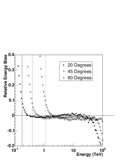
The error in the reconstructed energy () for a particular simulated -ray event with true energy and reconstructed energy is defined as . The mean value of is shown as a function of in Figure 11. For energies close to the threshold, there is a bias due to a selection effect, whereby events with energies reconstructed with too high a value are selected. In order to make an accurate energy spectrum it is necessary to define the useful energy range, so as to avoid the region of large energy bias. First the lowest energy bin in the bias histogram with a bias of less than 10% is found. The useful lower energy threshold is the maximum energy of this bin plus 10%. This safe energy threshold is also indicated in Figure 11 for each zenith angle. This energy threshold for the analysis is increased to take account of the shift in the energy scale when the optical efficiency correction is applied. It can be seen that the energy bias above the safe threshold does not depend on the zenith angle, up to energies in excess of 60 TeV.
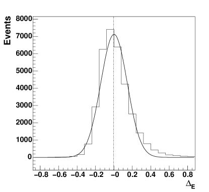
The distribution of , for -rays simulated with a power law spectrum with , at 50∘ zenith angle, is shown in Figure 12 for the standard analysis. The energy resolution for a particular energy range is defined as the width of this distribution. Events in this plot are selected above the safe threshold of 0.44 TeV in order to avoid the effect of the energy bias. The energy resolution defines the optimum binning for spectral reconstruction, as well as defining the minimum energy width of any resolvable spectral structure. It is possible to improve the energy resolution slightly by selecting only those events with higher telescope multiplicities and smaller impact parameters, at the expense of reduced event statistics.
6.3 Effective areas
The -ray flux from a source is estimated from the number of excess events passing the selection cuts for a particular data set using the effective area of the instrument. The effective area is a function of the zenith angle and offset of the source from the pointing direction, the energy of the event and the particular selection cuts used. The effective area is modeled from Monte Carlo simulations by counting the fraction of simulated events which trigger the detector and pass the selection cuts. This effective area has been estimated in two ways: as a function of the Monte Carlo energy of the simulated events () and as a function of the reconstructed energy (). While does not depend on the energy spectrum of the simulated -rays, the finite energy resolution makes sensitive to this; the effective areas are usually estimated assuming a power law distribution of . However, when estimating a flux using events binned in reconstructed energy, it is correct to use to estimate the effective area for each bin, when estimating the integrated effective area over the whole energy range one may use . In order to avoid a bias in the spectral reconstruction when using , it is necessary for the energy spectrum of the simulations to match that of the data, this is discussed further below. The effective areas as a function of true energy and reconstructed energy (for the standard selection cuts) are shown in Figure 13 for three zenith angles. As the effective area of the telescope system depends strongly on the zenith angle of the observations, it is determined for a range of angles and the value for a particular energy and zenith angle is determined by linear interpolation in and (Aharonian et al., 1999a).
| Pre-cut | Standard cuts | Loose cuts | Hard cuts | ||||||||
|---|---|---|---|---|---|---|---|---|---|---|---|
| Z | Threshold | rate | Threshold | rate | Threshold | rate | Threshold | rate | |||
| (∘) | (TeV) | () | (TeV) | () | (%) | (TeV) | () | (%) | (TeV) | () | (%) |
| 0 | 0.09 | 56.5 | 0.16 | 19.8 | 35 | 0.13 | 38.0 | 67 | 0.28 | 7.8 | 14 |
| 20 | 0.11 | 52.8 | 0.18 | 19.4 | 37 | 0.15 | 37.1 | 70 | 0.33 | 7.4 | 14 |
| 30 | 0.14 | 45.7 | 0.22 | 16.6 | 36 | 0.19 | 31.7 | 69 | 0.42 | 6.3 | 14 |
| 40 | 0.19 | 35.1 | 0.31 | 12.1 | 35 | 0.26 | 23.3 | 66 | 0.61 | 4.6 | 13 |
| 45 | 0.25 | 29.2 | 0.40 | 9.44 | 32 | 0.33 | 18.4 | 63 | 0.77 | 3.6 | 12 |
| 50 | 0.33 | 23.1 | 0.53 | 6.82 | 30 | 0.44 | 13.6 | 59 | 1.04 | 2.6 | 11 |
| 55 | 0.46 | 17.0 | 0.74 | 4.43 | 26 | 0.62 | 9.1 | 53 | 1.52 | 1.7 | 10 |
| 60 | 0.71 | 11.6 | 1.15 | 2.61 | 23 | 0.95 | 5.5 | 47 | 2.33 | 1.0 | 8.7 |
| 63 | 0.97 | 8.4 | 1.60 | 1.66 | 20 | 1.31 | 3.6 | 43 | 3.19 | 0.67 | 7.9 |
| 65 | 1.22 | 6.8 | 2.03 | 1.16 | 17 | 1.68 | 2.6 | 37 | 4.09 | 0.47 | 6.9 |
| 67 | 1.58 | 5.1 | 2.65 | 0.74 | 15 | 2.18 | 1.7 | 33 | 5.39 | 0.30 | 5.8 |
| 69 | 2.15 | 3.8 | 3.64 | 0.43 | 11 | 3.08 | 1.1 | 28 | 7.15 | 0.18 | 4.6 |
| 70 | 2.53 | 3.2 | 4.20 | 0.30 | 9 | 3.39 | 0.8 | 24 | 8.39 | 0.11 | 3.6 |
In order to simplify the application of the optical correction discussed in section 3.4, this correction is not applied in estimation of the effective area for each event. Since the distribution of Cherenkov light scales with the shower energy to a good approximation, the detection probability and hence the effective area depends primarily on the amount of light arriving at the camera, and not on the absolute energy of the -ray. Thus it is not necessary to recalculate the effective area lookup tables when the actual optical efficiency changes by a small amount. For larger changes this correction breaks down due to effects of the system trigger on events near the energy threshold. The selection cuts are made using the image intensity without optical correction, and the corrected intensity is only applied in the energy estimation. This method has been tested on Monte Carlo simulated sources with reduced optical efficiency, and it was verified that the correct flux is reconstructed.
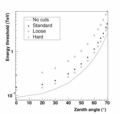
Instead of using the safe energy threshold as introduced above, the energy threshold for a set of observations has also been commonly defined as the peak in the differential rate vs. energy curve (Konopelko et al., 1999). This is formed by folding the effective area curve, as plotted in Figure 13(a) with the expected -ray flux from the source. This energy threshold is generally slightly lower than the safe threshold defined above, which is designed to ensure an accurate spectral reconstruction. There may even be a significant -ray signal below the safe threshold. The vertical lines in Figure 13 define the safe energy thresholds for each zenith angle. Figure 14 shows the predicted peak-rate energy threshold and -ray rate for a Crab-like source, based on simulations and projection from the Crab flux as measured by the HEGRA collaboration (Aharonian et al., 2000). Table 3 gives the pre-cut energy threshold as a function of zenith angle, along with the equivalent after the various selection cuts. It should be noted that the energy threshold, by this definition, depends on the spectrum of the source.
The effective area also varies with the position of the source in the field of view of the instrument. As larger energy showers are preferentially detected at higher impact distances, they appear closer to the edge of the field of view. Thus truncation of images for sources closer to the edge of the field of view tends to reject events at higher energies. Monte Carlo simulations are made at a range of source offset positions in order to make effective area curves and the effective area is interpolated for a particular observation. Table 3 also shows the event rates before selection cuts and after each of the selection cuts described above, as a function of zenith angle for a source similar in flux to the Crab nebula. These predictions are based on the effective areas estimated for a source offset by 0.5∘ from the observation position. The cut efficiencies in each case are also shown, with the (peak rate) energy thresholds.
7 Flux and spectral measurements
The data from observations of the Crab have been analysed using the technique described, individually by data set as outlined in Table 1, and combined. The analysis has been carried out for each of the sets of selection cuts as outlined in Table 2, using the reflected background method with 5 background regions. Table 4 outlines the numbers of events passing cuts in the on and off regions, as well as the background normalisation (), the number of excess events, the significance () of the excess, the rate of -rays passing cuts and the . Data Sets I-III are combined to give a total result. For example, the mean rate of -rays for the standard selection cuts is 6.0 with a significance of 27 . It can be seen that the rate of events passing cuts is strongly dependent on the zenith angle of the observations, as well as on the selection cuts used. Comparisons between Table 4 and Table 3 show that the effective area estimation correctly reproduces the -ray rate for the various data sets (within statistical errors). The mean rate for data set III, at a mean zenith angle of 54∘, is predicted to be 4.8 , while the measured value is . The loose cuts at 55∘ zenith angle keep 53% of the possible -rays, making them more suitable for spectral studies of strong sources.
| Data Set | method | on | off | excess | significance | rate | /dof | r.m.s. | |||
| () | % | ||||||||||
| I | std | 1866 | 749 | 0.20 | 1718 | 62.2 | 28.3 | 14 / 10 | 11.0 | ||
| II | std | 1976 | 1579 | 0.20 | 1667 | 53.2 | 22.2 | 27 / 13 | 16.0 | ||
| III | std | 4759 | 2417 | 0.20 | 4283 | 94.2 | 28.9 | 53 / 25 | 12.1 | ||
| all | std | 8601 | 4745 | 0.20 | 7666 | 124 | 27.0 | 133 / 51 | 14.9 | ||
| all | loose | 27970 | 61740 | 0.20 | 15570 | 106 | 23.1 | 143 / 51 | 22.2 | ||
| all | hard | 3058 | 376 | 0.19 | 2986 | 94 | 20.5 | 87 / 51 | 20.0 | ||
| all | extended | 25490 | 24160 | 0.51 | 13140 | 80 | 17.4 | 128 / 51 | 22.2 | ||
| all | std Ring | 8525 | 6573 | 0.14 | 7588 | 129 | 28.0 | 133 / 51 | 15.0 |
7.1 Run by run flux measurements
For the purpose of producing a light curve of the -ray flux from a source, the integrated flux above the threshold energy is calculated for each time period ( to ), assuming a particular spectral form for the source, such as a power law with photon index and flux normalisation in units of . The excess number of events seen from a source () is given by the following:
| (3) |
Here is the effective area as a function of zenith angle Z and true energy from Monte Carlo simulations. The flux normalisation can then be calculated by integrating the effective area up to some upper cutoff energy and over the integration time. The value of is imposed by the range of the Monte Carlo simulations and is normally above 100 TeV. The integral flux above threshold is usually quoted above the threshold energy for the observations, or alternatively above 1 TeV. Here the latter convention is used for simplicity.
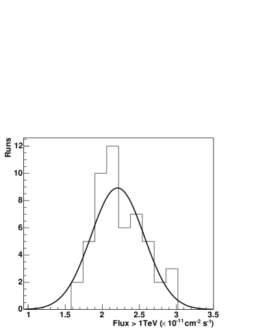
The fluxes measured for each data set included in this analysis, along with the mean fluxes for data sets I-III are given in Table 4. The mean flux is also given for the various sets of selection cuts described in Table 2. The rms variation in the mean flux per data set is 8%, while the rms variation in the run-by-run fluxes is 14.9%, the typical statistical error on a single run is 5% for moderate zenith angles and offsets. Figure 15 shows light-curves for data sets I, II and III, while the distribution of run-by-run flux is shown in Figure 16, for all of the data.
It can be seen that the long-term variations in the run-by-run flux after the correction for changes in the detector optical efficiency are small compared to the short-term variations, mainly due to atmospheric effects. The mean flux in data sets II and III, taken in January 2004, is 10% higher than that seen in data set I, which was taken in October of 2003. This difference is smaller than the rms spread of either data set, and can be explained by differences in the atmospheric conditions between the two periods. No correction is made to the run-by-run flux for short term variations in the atmospheric conditions. Such corrections are under study and will be the focus of a future paper.
Systematic errors in the flux due to selection cuts and effective area estimates have been studied by applying the various selection cuts described to the data and measuring the integral flux. The results are outlined in Table 4. The rms in the measured fluxes is 15%. A possible systematic error in the integral flux measurement due to the background estimation method has been tested by applying the ring-background method, as described above to calculate a flux. It can be seen that the reconstructed flux differs only slightly with the two methods.
7.2 Energy spectrum
The energy spectrum of the Crab has been measured using the data described here. The method used for deriving the energy spectrum is similar to those described by Mohanty et al. (1998), Aharonian et al. (1999b) and Aharonian et al. (2004b). An energy spectrum is fit for each data set and for the combined data.
The bin size for the energy spectrum is set depending on the overall significance of the signal. The maximum possible energy bin is defined by the simulations, which extend to above 400 TeV at 50∘ zenith angle. Only energies above the safe threshold as defined above are used for spectral determination.
In each energy bin above the minimum energy the differential flux is calculated by summing over the on source events , weighted by the inverse of the effective area () as a function of the reconstructed energy of each event. The normalised sum of the weighted off events is then subtracted. The difference is weighted by the live-time for that bin (T) and the bin width ():
| (4) |
In the case where runs are combined with varying zenith angles, and thus varying useful energy thresholds, the live-time is calculated for each energy bin separately. The result is scaled by the appropriate live-time to give the -ray flux in each energy bin. The error on the flux in each energy bin is estimated using standard error propagation. A spectral energy function (for example a power law distribution) is fit to the flux points using the least-squares method. The maximum energy for spectral fitting is chosen so as to have a significance in that bin greater than 2.
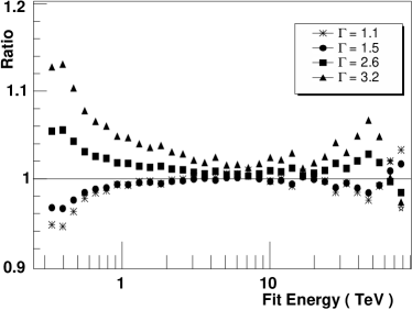
Since the estimation of the effective area as a function of reconstructed energy, , depends on an assumed spectral slope, it is strictly correct to adjust for the fitted spectrum and then re-fit, repeating until the fit converges (Aharonian et al., 1999b). Figure 17 shows the bias as a function of energy introduced by using an assumed photon index of 2.0 for the effective area estimation, given true spectra with indices ranging from 1.1 to 3.2. It can be seen that at 440 GeV, the differential flux for a source with an intrinsic photon index of 2.6 is overestimated by 5%, while the differential flux given a true photon index of 1.5 is underestimated by 4%. For energies well above threshold the bias is less than 5% for a wide range of photon indices. Thus the effect of this correction on the Crab spectrum is small and was neglected for this analysis.
| Mean energy | excess events | Significance | Differential flux |
|---|---|---|---|
| (TeV) | () | ||
| 0.519 | 975 | 42.9 | |
| 0.729 | 1580 | 56.0 | |
| 1.06 | 1414 | 55.3 | |
| 1.55 | 1082 | 47.3 | |
| 2.26 | 762 | 39.5 | |
| 3.3 | 443 | 29.5 | |
| 4.89 | 311 | 24.9 | |
| 7.18 | 186 | 19.6 | |
| 10.4 | 86 | 13.1 | |
| 14.8 | 36 | 8.1 | |
| 20.9 | 23 | 7.5 | |
| 30.5 | 4 | 2.9 |
The number of excess events and significance is given for each energy bin along with the differential flux in Table 5. Only statistical errors are given here. A significant signal is seen in every energy bin from the threshold energy of 440 GeV up to 20 TeV, and a marginal signal is seen at the maximum bin of mean energy 30.5 TeV. The spectrum is shown in figure 18. The fit of a power law function to the combined data with the standard analysis cuts yields and differential flux normalisation at 1 TeV (PL in Table 6).
In the combined spectral fit there is evidence for a steepening of the energy spectrum; a fit of a power law with an exponential cutoff: , gives a differential flux normalisation at 1 TeV , with and a cutoff energy TeV. The for this fit is 15.9 with nine degrees of freedom. This compares with a of 104 with ten degrees of freedom for the straight power law fit, thus the fit including an exponential cutoff is clearly favoured. A broken power law fit (BPL in Table 6):
gives a differential flux normalisation , with below the break energy of TeV. The photon index above the break is , and the /dof of the broken power law fit is 28.6/8. This fit includes a term (S) for the width of the transition region, which is fixed to 0.3.
| Data Set | Selection | |||||||
|---|---|---|---|---|---|---|---|---|
| cuts | (TeV) | (TeV) | () | (TeV) | () | |||
| I | std | 0.41 | 19 | 11.8 / 7 | ||||
| II | std | 0.41 | 100 | 26.3 /10 | ||||
| III | std | 0.45 | 65 | 12.6 / 9 | ||||
| all | std | 0.41 | 40 | 15.9 / 9 | ||||
| all (BPL) | std | 0.41 | 40 | 28.6 / 8 | ||||
| all (PL) | std | 0.41 | 40 | 104 / 10 | ||||
| all | loose | 0.34 | 71 | 7.1 /10 | ||||
| all | hard | 0.73 | 71 | 17.4 / 8 | ||||
| all | extended | 0.45 | 30 | 14.6 / 8 | ||||
| all(uncorr.) | std | 0.34 | 33 | 21.8 / 9 | ||||
| all(ring) | std | 0.41 | 86 | 14.9 /10 | ||||
| Whipple | ||||||||
| CAT | ||||||||
| HEGRA |
The flux and spectral measurements for the separate data sets are summarised in Table 6. The rms spread of the photon index from data set to data set is 0.04. The rms spread in the integral flux, calculated from the fitted spectrum, is 15%, with a statistical error of 2% on the integrated flux for the combined data. Figure 18(a) shows the energy spectral points superimposed for the three data sets used in the spectral analysis, the residuals about the combined fitted spectrum are shown underneath. Figure 18(b) shows the energy spectral fit, along with residuals, for the combined data sets I-III. The spectral fits for the various selection cuts are also included in Table 6, as is the fit for the ring background model. For comparison the fit spectrum calculated without the optical efficiency correction is also included.
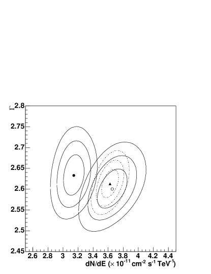
Figure 19 shows a 2-d plot of the fitted photon index against the flux normalisation for each data set analysed, here a simple power law fit has been made for simplicity. The error contours, estimated using the least-squares method, are also shown. It can be seen that the three data sets are compatible at the level; data set II includes large zenith angle data, and is fitted with a slightly softer spectrum, caused by the higher energy threshold of these observations and the significant curvature seen in the spectral measurements.
The combined data sets I-III have also been analysed with the various selection cuts described in Table 2, and a spectrum fitted. The rms spread in the photon index between the various analyses is 0.08, however this includes the effect of the very different energy threshold for the hard selection cuts, which may give rise a softer photon index if the source spectrum is intrinsically curved. The rms spread of the reconstructed integral flux is 8%, which indicates that the reconstructed flux is not strongly dependent on the details of the analysis method. The use of the ring-background method results in a flux and spectral slope similar to that reconstructed using the standard reflection method.
7.3 Estimation of systematic errors
The systematic error on the absolute flux is estimated from the various independent contributing factors, as discussed in section 2.2. These errors are summarised in Table 7. The total estimated systematic error, after correction for degradation in the optical efficiency, is 20%. The sources of systematic error include uncertainties due to the shower interaction model and the atmospheric model used in the Monte Carlo simulations. Also included is the estimated uncertainty in the flux due to the effect of missing pixels, which has been conservatively estimated at 5%, and the effect of uncertainty in the live-time measurement, which is less than 1%. The uncertainty in flux due to selection cuts is estimated from the rms of the flux and spectral slope measurements detailed in Table 6, as is the uncertainty due to the background model. The run-by-run rms over the entire set of data is 15%, this is thought to mainly be due to variations in the atmosphere, and thus is included in the systematic error as an independent factor. The rms of the spectral estimations for the various datasets in Table 6 is used to estimate the uncertainty in the spectral slope, which is 0.1.
8 Conclusions
A strong signal has been detected from the Crab nebula during the commissioning phase of the H.E.S.S. instrument and with the complete instrument. An energy spectrum has been measured, with a differential spectrum described by a power law with slope and an exponential cutoff at TeV. The integral flux above 1 TeV is .
| Uncertainty | Flux | Index |
| MC Shower interactions | 1% | |
| MC Atmospheric sim. | 10% | |
| Broken pixels | 5% | |
| Live time | 1% | |
| Selection cuts | 8% | 0.08 |
| Background est. | 1% | 0.01 |
| Run-by-run variability | 15% | - |
| Data set variability | - | 0.05 |
| Total | 20% | 0.09 |
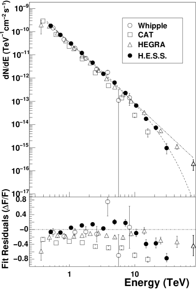
Marginal steepening in the spectrum measured on the Crab nebula has been previously claimed by Aharonian et al. (2004b) in studies of the Crab with the HEGRA experiment. Figure 20 compares the Crab spectrum from this study with measurements by HEGRA, CAT and Whipple. Acceptable agreement is seen up to 10 TeV between the experiments, although the CAT result gives a somewhat steeper spectrum; the rms variation in integral flux between the four experiments is 22%. Above 10 TeV the energy spectrum as seen by H.E.S.S. steepens significantly, in particular compared to HEGRA.
The softening seen in the Crab spectrum at high energies is consistent with models of inverse Compton emission due to a population of electrons extending up to PeV energies. Due to the high magnetic field in the Crab nebula, the dominant target photon field for emission is probably created by synchrotron emission from the same electron population (Hillas et al., 1998). More detailed models of -ray emission in the Crab nebula are discussed by Atoyan & Aharonian (1996); de Jager & Harding (1992).
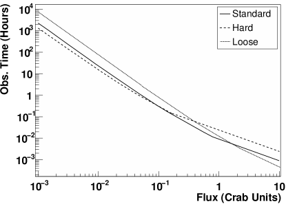
Given the agreement between the Monte Carlo simulations and the data, one can use the simulations to predict the time required to detect a point source of a certain strength as a function of zenith angle. In Figure 21 we show the time as a function of signal strength required for a detection at 20∘ zenith angle, for the selection cuts described here. The H.E.S.S. array is capable of detecting a point source with a flux of 1% of the Crab nebula in 25 hours, or alternatively detecting a source of similar strength to the Crab in 30 seconds. The sensitivity for extended sources decreases approximately linearly with the source extension. This sensitivity is unprecedented in the field of VHE astrophysics and opens a new window for sensitive and precise measurements of VHE -ray sources.
Acknowledgements.
The support of the Namibian authorities and of the University of Namibia in facilitating the construction and operation of H.E.S.S. is gratefully acknowledged, as is the support by the German Ministry for Education and Research (BMBF), the Max Planck Society, the French Ministry for Research, the CNRS-IN2P3 and the Astroparticle Interdisciplinary Programme of the CNRS, the U.K. Particle Physics and Astronomy Research Council (PPARC), the IPNP of the Charles University, the South African Department of Science and Technology and National Research Foundation, and by the University of Namibia. We appreciate the excellent work of the technical support staff in Berlin, Durham, Hamburg, Heidelberg, Palaiseau, Paris, Saclay, and in Namibia in the construction and operation of the equipment.References
- Achterberg et al. (2001) Achterberg, A., Gallant, Y. A., Kirk, J. G., & Guthmann, A. W. 2001, MNRAS, 328, 393
- Aharonian et al. (1999a) Aharonian, F. A., Akhperjanian, A. G., Barrio, J. A., et al. 1999a, A&A, 342, 69
- Aharonian et al. (1999b) Aharonian, F. A. et al. (HEGRA Collaboration) 1999b, A&A, 349, 11
- Aharonian et al. (2000) Aharonian, F. A. et al. (HEGRA Collaboration) 2000, ApJ, 539, 317
- Aharonian et al. (2004a) Aharonian, F. A. et al. (H.E.S.S. Collaboration) 2004a, Astroparticle Physics, 22, 109
- Aharonian et al. (2004b) Aharonian, F. A. et al. (HEGRA Collaboration) 2004b, ApJ, 614, 897
- Atkins et al. (2003) Atkins, R., Benbow, W., Berley, D., et al. 2003, ApJ, 595, 803
- Atoyan & Aharonian (1996) Atoyan, A. M. & Aharonian, F. A. 1996, A&AS, 120, C453
- Aye et al. (2005) Aye, K.-M., Brown, A. M., Chadwick, P. M., et al. 2005, in AIP Conf. Proc. 745: High Energy Gamma-Ray Astronomy, ed. F. A. Aharonian, H. J. Völk, & D. Horns, 724–729
- Baillon et al. (1993) Baillon, P., Behr, L., Danagoulian, S., et al. 1993, Astroparticle Physics, 1, 341
- Bernlöhr et al. (2003) Bernlöhr, K., Carrol, O., Cornils, R., et al. 2003, Astroparticle Physics, 20, 111
- Bernlohr (2000) Bernlohr, K. 2000, Astroparticle Physics, 12, 255
- Bolz (2004) Bolz, O. 2004, PhD thesis, Karl-Ruprecht University Heidelberg
- Borgmeier et al. (2003) Borgmeier, C. et al. 2003, in Proceedings of the 28th International Cosmic Ray Conference (Tsukuba), Vol. 1, 891
- Cornils et al. (2003) Cornils, R., Gillessen, S., Jung, I., et al. 2003, Astroparticle Physics, 20, 129
- Coroniti (1990) Coroniti, F. V. 1990, ApJ, 349, 538
- Daum et al. (1997) Daum, A. et al. 1997, Astroparticle Physics, 8, 1
- Davies & Cotton (1957) Davies, J. & Cotton, E. 1957, Journal of Solar Energy, 1, 16
- de Jager & Harding (1992) de Jager, O. C. & Harding, A. K. 1992, ApJ, 396, 161
- Feldman & Cousins (1998) Feldman, G. J. & Cousins, R. D. 1998, Phys. Rev. D, 57, 3873
- Fomin et al. (1994) Fomin, V. P., Stepanian, A. A., Lamb, R. C., Lewis, D. A., Punch, M., & Weekes, T. C. 1994, Astroparticle Physics, 2, 137
- Funk et al. (2004) Funk, S., Hermann, G., Hinton, J., et al. 2004, Astroparticle Physics, 22, 285
- Goret et al. (1993) Goret, P., Palfrey, T., Tabary, A., Vacanti, G., & Bazer-Bachi, R. 1993, A&A, 270, 401
- Hillas (1985) Hillas, A. 1985, in Proc. 19nd I.C.R.C. (La Jolla), Vol. 3, 445
- Hillas et al. (1998) Hillas, A. M. et al. 1998, ApJ, 503, 744
- Hofmann et al. (1999) Hofmann, W., Jung, I., Konopelko, A., et al. 1999, Astroparticle Physics, 12, 135
- Hofmann et al. (2003) Hofmann, W. et al. 2003, in Proceedings of the 28th International Cosmic Ray Conference (Tsukuba), Vol. 1, 2811
- Kennel & Coroniti (1984) Kennel, C. F. & Coroniti, F. V. 1984, ApJ, 283, 710
- Konopelko et al. (1999) Konopelko, A., Hemberger, M., Aharonian, F., et al. 1999, Astroparticle Physics, 10, 275
- Lemoine et al. (2006) Lemoine, M. et al. 2006, Astroparticle Physics (accepted) astro-ph/0601373
- Leroy et al. (2004) Leroy, N. et al. 2004, in SF2A-2004: Semaine de l’Astrophysique Francaise, meeting held in Paris, France, June 14-18, 2004, Eds.: F. Combes, D. Barret, T. Contini, F. Meynadier and L. Pagani EdP-Sciences, Conference Series, meeting abstract
- Li & Ma (1983) Li, T.-P. & Ma, Y.-Q. 1983, ApJ, 272, 317
- Masterson et al. (1999) Masterson, C. et al. 1999, in Proceedings of High Energy Gamma-Ray Astronomy 2000 (AIP), Vol. 558, 753–756
- Masterson et al. (2003) Masterson, C. et al. 2003, in Proceedings of the 28th International Cosmic Ray Conference (Tsukuba), Vol. 1, 2323
- Michel (1994) Michel, F. C. 1994, ApJ, 431, 397
- Mohanty et al. (1998) Mohanty, G. et al. 1998, Astroparticle Physics, 9, 15
- Pühlhofer et al. (2003) Pühlhofer, G. et al. 2003, Astroparticle Physics, 20, 267
- Perryman & ESA (1997) Perryman, M. A. C. & ESA. 1997, The HIPPARCOS and TYCHO catalogues. Astrometric and photometric star catalogues derived from the ESA HIPPARCOS Space Astrometry Mission (Noordwijk, Netherlands: ESA Publications Division, Series: 1200)
- Rees & Gunn (1974) Rees, M. J. & Gunn, J. E. 1974, MNRAS, 167, 1
- Smith et al. (2000) Smith, D. A., Bazer-Bachi, R., Bergeret, H., et al. 2000, Nuclear Physics B Proceedings Supplements, 80, 163
- Vincent et al. (2003) Vincent, P. et al. 2003, in Proceedings of the 28th International Cosmic Ray Conference (Tsukuba), Vol. 1, 2887
- Weekes et al. (1989) Weekes, T. C., Cawley, M. F., Fegan, D. J., et al. 1989, ApJ, 342, 379
- Weiler & Panagia (1980) Weiler, K. W. & Panagia, N. 1980, A&A, 90, 269
- Wilson (1972) Wilson, A. S. 1972, MNRAS, 157, 229