Results from the adaptive optics coronagraph at the WHT
Abstract
Described here is the design and commissioning of a coronagraph facility for the 4.2 metre William Herschel Telescope (WHT) and its Nasmyth Adaptive Optics system for Multi-purpose Instrumentation (NAOMI). The use of the NAOMI system gives an improved image resolution of arcsecs at a wavelength of 2.2m. This enables the Optimised Stellar Coronagraph for Adaptive optics (OSCA) to suppress stellar light using smaller occulting masks and thus allows regions closer to bright astronomical objects to be imaged. OSCA provides a selection of 10 different occulting masks with sizes of 0.25 - 2.0 arcsecs in diameter, including two with full greyscale Gaussian profiles. There is also a choice of different sized and shaped Lyot stops (pupil plane masks). Computer simulations of the different coronagraphic options with the NAOMI segmented mirror have relevance for the next generation of highly segmented extremely large telescopes.
keywords:
instrumentation: adaptive optics, miscellaneous;1 Introduction
Compared to a standard coronagraphic imaging system, one with adaptive optics (AO) gives much higher spatial resolution and a high dynamic range allowing the environments of bright objects to be studied closer in than ever before (Malbet, 1996). Additional instrumentation used in combination with a coronagraph allows other new areas of research to be pursued. There are few coronagraphs that have this facility, e.g. CIAO on Subaru, which has a choice of linear polarimeters (Murakawa, 2003) and OSCA on the WHT, which has a spectroscopic capability (with the OASIS integral field unit).
The adaptive optics system at the WHT, NAOMI, consists of a single Shack-Hartmann wavefront sensor normally using sub-apertures and a 76-element segmented mirror. This is a reasonably high-order AO system and can offer partial correction for wavelengths down to 700nm. NAOMI has been at the telescope since 2000 and during early 2003 was moved to a new environment-controlled laboratory at the opposite Nasmyth platform. This provides a more dust-free and thermally stable environment and so should improve the performance of the system (Myers, 2003).
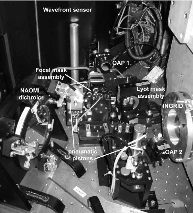
OSCA is a fully deployable instrument which when in use leaves the focus of the NAOMI beam unchanged. This enables OSCA to be used in conjunction with a number of instruments that have already been commissioned at the WHT (Fig. 1). The main imaging camera used with OSCA is the Isaac Newton Group Red Imaging Device (INGRID); a element HgCdTe cooled near-IR detector at the NAOMI focus. The pixel scale when used with NAOMI is 0.04 arcsec/pixel, hence Nyquist sampling is only obtained down to H-band (m). Prior to the detector but within the camera cryo-chamber are a set of 3 wheels containing broadband filters (Z - K), narrowband filters and a choice of pupil stops respectively. OSCA also has the option of being used in conjunction with an integral field spectrograph (OASIS) for imaging and spectral analysis at visible wavelengths.
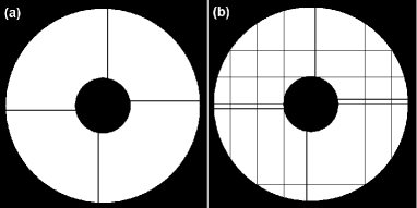
An important criterion in creating a high contrast imaging system is keeping scattered light to a minimum. Compared to other AO coronagraphs, the system at the WHT allows the insertion of an occulting mask in a focal plane before the AO system as well as those in the focal plane within the AO. Ideally this ‘pre-AO’ mask would be made of a dichroic material that is transparent to the wavelengths used for wavefront sensing and opaque to the science/observation wavelength. The many square segments in the NAOMI adaptive mirror contribute more scattered light than a similar sized continuous face-sheet mirror and the gaps between the segments also have a higher emissivity in the infra-red, so this additional pre-AO stop for the NAOMI-OSCA system could be extremely useful in cutting down scattered light at the science wavelengths and thus improving sensitivity in the final image. An additional means of reducing the diffraction effects of the segmented mirror subsequent to the application of a focal occulting mask is the use of a Lyot (pupil) mask that is matched to the segmented mirror. Such a mask is shown in Fig. 2 (inset top, left-hand mask) and discussed in §3.2.
OSCA was commissioned at the WHT in mid-2002 and became available for general use in 2003b. The OSCA + OASIS option is currently unavailable although work is being planned to rectify the problem.
2 Design overview
OSCA (Thompson, 2003) is based on the classic Lyot (Lyot, 1939) coronagraph design. The sizes of the focal plane masks (0.25 - 2.00 arcsec) were chosen to take advantage of the improved point-spread function (PSF) offered by NAOMI. Ten focal plane masks are available for selection on the instrument. One is for alignment purposes only and two are of a more novel Gaussian profile compared to the standard hard edged circular discs.
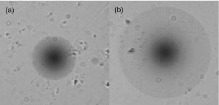
The standard focal plane (occulting) masks are made of chromium, deposited on the substrates by a contact-photolithography process. Computer simulations, both here (in §3) and by others (Nakajima, 1994), have shown that occulting masks of a Gaussian profile give better suppression than the standard solid disc design. However creating such a mask is not trivial. Canyon Materials Ltd have a patented glass formula, HEBS (High Energy Beam Sensitive)-glass, which behaves in a similar way to photographic film. HEBS-glass is sensitive towards electron-beam exposure whereby exposure with a certain electron-beam dosage changes the optical density of the material. In this way the HEBS-glass can act as a mask material and by varying the electron-beam exposure different greyscale (optical density) levels can be written into the glass (Walter, 1996). To create the Gaussian profile masks for OSCA (Fig. 3) 669 different greyscale levels were written in ring steps of m width. One restriction on their usage is that the glass is only suitable for the wavelength range 0.4 - 0.8m. There is a visible camera on OASIS, so these masks were included in OSCA with this use in mind.
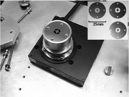
The pupil plane masks are manufactured from 0.25mm thick, hard stainless steel by a process of photo-chemical machining. Since OSCA is located at a Nasmyth focus of the telescope, the telescope field derotator (which ensures the observation object does not rotate as the telescope tracks on its alt-az mounting) has the effect of rotating the telescope pupil. Since the standard Lyot mask used in OSCA includes vane masking, the Lyot mask must be rotated to maintain the alignment with the telescope pupil image. The standard Lyot mask mounted on a Newport SR50 step motor rotation stage is shown in Fig. 2. Additional pupil stops (non-rotating) were manufactured at the ING to go in the INGRID pupil filter wheel. These provide cooled masks for OSCA which are particularly important for observing in K-band otherwise the thermal background noise is very high.
An important requirement of the optical design was to ensure that the focal position was unaltered with OSCA deployed in the beam path and since space is very limited on the optical table, to fit this design into a very small spatial envelope (see Fig. 1). The optical specifications were that it should be diffraction limited at a wavelength of 2.2m over the full field of view and have less than 0.1 arcsec distortion over the field for the full wavelength range. Additionally, the system has an exit pupil in the same position as that for NAOMI so providing an unchanged optical interface to subsequent optics which were designed to work with NAOMI. The field of view for OSCA is designed to be 20 arcsec, but ghosting within the INGRID camera optics has currently reduced this to 15 arcsec. The system also has a 1:1 magnification to leave the NAOMI field-scale unchanged. To accommodate the required wavelength range of 0.4 - 2.4m all mirrors in the system were coated with protected silver on Zerodur. Similarly all transmissive optics were made from an infra-red (IR) grade fused silica (Spectrosil WF) which gives over 90% transmission across the entire specified wavelength range and can be polished to a very high surface quality.
To prevent ghosting within OSCA the substrates for the focal plane masks have a slight wedge angle. The wedges are also tilted slightly in the design, to ensure the ghost beam misses the pupil. This is achieved by aligning the whole occulting mask filter-wheel assembly at a slight angle to the beam and checking that the ghost-beam is thrown completely out of the optical path.
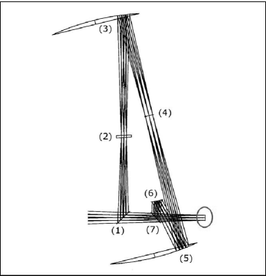
The path of light through OSCA is shown in Fig. 4 and is numbered sequentially along the beam direction. When deployed in the NAOMI beam, flat mirror (1) picks up the beam. The occulting masks are located at the focal plane (2). The Lyot stop is located at the pupil plane (4). The mirrors at (3) and (5) are a pair of off-axis paraboloids, and finally the flats at (6) and (7) position the focus to the original NAOMI focal position.
The important mechanical requirements of the OSCA system were for it to be thermally stable from -5∘C to 25∘C (i.e. positional accuracy is held within the specified tolerances and that the components will function correctly), vibrationally stable, for none of the components to infringe upon the beam path within or outside of OSCA, the entire system to be deployable in and out of the beam with a repeatability of m, the centre of the focal plane masks to be automatically positioned to m, 5 year component lifetime (standard ING requirement) and for the heat output to be minimised so as not to interfere with INGRID.
The unit can be automatically deployed to interrupt the beam passing through to INGRID and the OASIS pick-off mirror. A vertical deployment was implemented due to the space restrictions. From Fig. 1 it can be seen that OSCA comprises of a base plate which is rigidly clamped to the bench and a top plate on which all the opto-mechanical components are seated. Deployment is achieved by the top plate pivoting about a groove and cone of hardened stainless steel at the first off-axis paraboloid end of OSCA with a pneumatic actuator at the second off-axis paraboloid end to bring the plate up into the beam.
The focal masks are located within a wheel that can be automatically selected from the control room. Each focal mask is re-located to high precision by use of notches around the mounting wheel and a pneumatically deployed arm which locks into the notches (detent-arm). This facility along with the capability to deploy OSCA into and out of the beam accurately and automatically allows for a flexible and versatile observing program over the course of a night.
3 System simulations
Computer simulations were written and run for a coronagraphic system with a segmented adaptive optics corrector (as in NAOMI). A program that generates Kolmolgorov type turbulence phase-screens (Lane, 1992) was used as the input to the simulation. This program does not incorporate the outer scale of atmospheric turbulence, although this effect is negligible over a 4m aperture.
Unless stated otherwise, the simulations discussed here used a phase-screen (aperture) size of padded with zeros to four times its size for the fast Fourier transforms (FFT), giving a focal plane. In the final image this results in a higher resolution than that achieved by INGRID. The AO and coronagraph code were developed in Matlab (Thompson, 2004) based on an original C-code by A.P. Doel. The simulations include photon noise in the wavefront sensor, mirror hysteresis and pixel noise in the detector.
3.1 Effect of focal mask properties on performance
The chromium disc focal plane masks in OSCA were measured to transmit more light at longer wavelengths. To model the effect this might have on the suppression performance, a set of simulations were performed using a 1 arcsecond disc mask function with transmission values of 0, 0.1, 1 and 10%. These transmission levels are equivalent to neutral density (ND) values of , 3, 2 and 1. A 2000 phase-screen AO simulation with the coronagraph using an 80,20 (80% primary masking, 120% secondary masking) Lyot stop was run for each of these disc transmissions and the results plotted in Fig. 5.
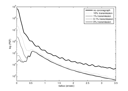
The suppression factors (no coronagraph/with coronagraph) for these masks measured at a radius of 1 arcsec (i.e. 0.5 arcsec from the edge of the mask), starting with the 0% transmission are: 4.80, 4.80, 4.65 and 3.83 respectively. Therefore for small amounts of transmission, 1% and less, there is negligible loss of suppression performance compared to a totally opaque mask. For a 10% transmission mask the difference becomes significant, with the factor loss in suppression measured at 1 arcsecond radius being 1.25 compared to the opaque mask.
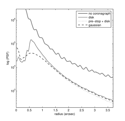
Simulations were also performed for a wide variety of different shaped focal masks, Fig. 6 shows the simulated suppression profiles of those mask types most relevant for OSCA. As expected, the best suppression close in to the mask (0.5-1.0 arcsec) is achieved by using a Gaussian shaped focal mask. For distances arcsec the disc mask with a pre-AO stop gives the best suppression. The segmented adaptive mirror contributes a significant amount to the diffracted/scattered light in the image, so reducing the unwanted light falling on the mirror acts to reduce the background. The effect of smoothing the edges of sharp-edged masks and using Gaussian profiled masks improves the suppression by reducing additional diffracted light in the pupil plane (see the result of diffraction in the pupil plane by a hard-edged mask in Fig. 9(b)). This then increases the efficiency of the Lyot mask in removing the light in the remaining wings of the PSF. The light from remainder of the PSF, when viewed at the next pupil plane is then mostly concentrated about the edges of this aperture image (primary, secondary, vanes, segment edges etc.), i.e. the parts of the aperture image that contain the most high spatial frequencies.
3.2 Effect of a segmented mirror on performance
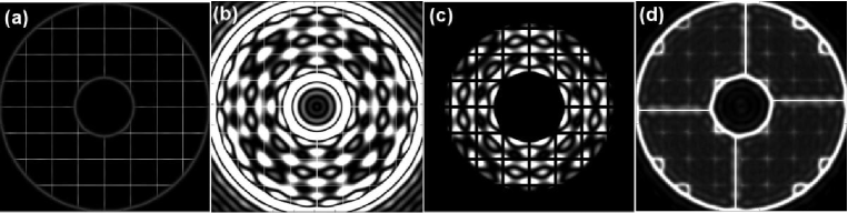
There are a number of additional factors which need to be taken into consideration when designing a coronagraph with an adaptive segmented mirror. The segmentation pattern will cause additional unwanted diffraction effects which distribute light away from the central maximum, this includes the gap between the segments and any phase effects due to step mismatching between the segments. The pupil in OSCA (no focal or Lyot mask) is illustrated in Fig. 7. The normalised peak intensity ratio of the PSF produced by this aperture compared to the same aperture without segmentation (with no phase mismatching) is 0.97. From this simple calculation it is seen that a segmented AO system is of lower contrast by design compared to a continuous face-sheet mirror.
However, the loss in performance when using a coronagraph with a segmented mirror is much more than 3%. The reason for this is can be seen by examining the distribution of light in the pupil plane after the application of the focal stop, an example is given in Fig. 9(a). For the case of a Gaussian focal plane mask applied to the PSF obtained by using the aperture in Fig. 7(b), it is found that 45% of the total light in the pupil is distributed about the segment edges. So if a normal Lyot mask is used here (primary, secondary and vane masking) a significant proportion of the light from that remaining of the masked star will stay in the final image, thus reducing the suppression performance.
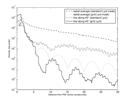
The use of a more complex Lyot mask which masks the individual mirror segments as well as the telescope primary and secondary gives improved suppression performance compared to a Lyot mask which only masks the telescope primary and secondary. The individual segments in NAOMI are 7.6mm across with a 0.1mm gap between each one. The ratio of gap to segment size is the same order of magnitude to those proposed for future segmented extremely large telescopes (ELTs), i.e. 1m segments with 10mm gaps. Hence these results have relevance for high contrast imaging with ELTs. To model the effect of the gaps between the NAOMI segments more pixels are required across the aperture. The results shown in Fig. 8 were obtained using 1024 pixels across the aperture diameter with a 2 pixel gap between the mirror segments. Due to the size of this array this was a static simulation (i.e. not an AO simulation), a 2 times padding factor was used in the FFTs. The lines show the mean trends (a convolution filter has been applied to flatten out the high frequency periodicity) that the segmented aperture produces. In the high contrast direction ( to image axes) the benefit is most evident at distance arcsec from the centre, reducing counts by 2 orders of magnitude. For the radial averaged lines (which include the bright axial diffraction peaks) the benefit of the grid Lyot mask is noticeable from 1 arcsec.
For the full AO simulations (with 256 pixels across the aperture, padding and no gaps), the effect of phase mismatching between the segments can be seen as an over-intensity about the segments in the pupil plane subsequent to the application of the occulting mask, as shown in Fig. 9(d). Segments with the greatest intensity are those that are ‘turned off’ and so have the greatest phase step between them and adjacent segments. Taking gaps and phase errors between segments into consideration the benefit of a Lyot mask which masks the individual mirror segments becomes apparent.
A Lyot mask matched to the NAOMI mirror segments (80% under sizing of segments) was created with OSCA (shown in Fig. 2 (inset top, left-hand mask)) but is as yet untested on-sky. The mask requires very careful alignment and there has been insufficient commissioning time to trial this new mask. Telescope schedules allowing, trials may be performed towards the end of 2005.
4 Laboratory testing the focal plane masks
A spatially filtered collimated 613nm laser beam and a series of lenses and masks were arranged in the laboratory to simulate an ideal coronagraphic system. A simple iris was used for the entrance aperture and another one at 80% diameter to act as the Lyot mask. Images were recorded at the final focus for a variety of different occulting spots using a Santa Barbara Instrument Group (SBIG) camera, this consists of a pixel, Peltier-cooled CCD. The usual calibrations were taken - dark frames and background images between every image.
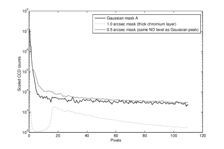
These tests were performed after OSCA had been shipped to the WHT. The Gaussian masks were commissioned at a later date and a method to compare them to the standard masks on OSCA was devised. The lithography template plate was used in place of a 0.5 arcsec disc occulting mask, approximately the same as the full-width half-maximum of the Gaussian masks. The ND value of this mask was also closely matched to the max ND level at the peak of the Gaussian mask so offered a good comparison between the two different shapes of mask. The 1.0 arcsec mask tested here was a spare from OSCA and had an ND level of 5.5 (compared to 2.5 for the 0.5 arcsec mask and Gaussian) at this wavelength.
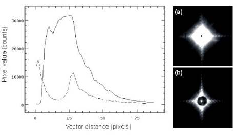
Images were taken at the focus for all 3 different occulting masks, both with and without the Lyot mask. The images were reduced (dark and background subtracted and scaled for exposure differences) and then radial averages were plotted about the PSF peak. Fig. 10 shows the radial averages of the 3 different masks using the same Lyot mask. The 1.0 arcsec mask performs best of all, entirely due to its much larger size (covers the area thus removing much more of the PSF) and greater opacity. Comparing the other two masks which differ mainly in their shape rather than any other factors it can be seen that as the simulations predicted, the Gaussian shaped mask provides greater suppression closer in to the centre than the disc mask does.
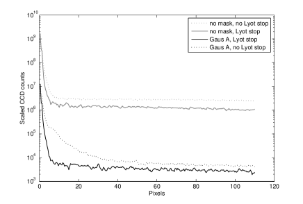
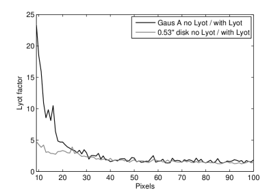
Fig. 11 shows the significant effect adding a Lyot stop has on the suppression with the Gaussian mask, the CCD count at 10 pixels from the centre is , compared to for the 0.50 arcsec disc. Without a Lyot stop the value at 10 pixels from the centre for the Gaussian mask is and for the 0.50 arcsec disc is . This shows that for a Gaussian mask at the focus compared to a solid disc of comparable size, an undersized pupil stop further along the beam works to greater advantage in suppressing the final image. In terms of attenuation factors, the effect of adding the Lyot stop (measured at 10 pixels) with the Gaussian mask compared to no Lyot stop brings about a factor of 16 drop in measured CCD counts, for the 0.50 arcsec disc this factor is only 4.6. At 60 pixels, for the Gaussian the factor is 1.83 and for the 0.50 arcsec disc 1.75, approximately the same. The extra effectiveness of the Lyot stop with the Gaussian mask is therefore greatest close in to the mask, with the ‘Lyot factor’ dropping as the distance from the mask increases until it converges with the 0.50 arcsec mask values. This trend is shown in Fig. 12.
5 Commissioning results
OSCA and its electronics were shipped to La Palma at the beginning of May 2002 and it underwent first commissioning soon after. Only two nights on-sky were allocated for the OSCA commissioning so time was very limited. The first night was plagued by extremely bad seeing throughout (5 arcsec recorded at worst) and the AO system could not be used. Since the largest occulting mask in OSCA is 2.0 arcsec it was also not feasible to do any performance testing.
The last night (24th May) saw very variable seeing over the course of the night and sky-location and the presence of high cirrus cloud also caused problems on occasion. NAOMI was used although centring objects on the OSCA occulting masks was difficult when the seeing was bad and OSCA performance was degraded. The average seeing was 1.5 arcsec, and with the AO system an average corrected PSF width of 0.5 arcsec was obtained. Fig. 13 shows the suppression obtained using OSCA in H-band using the 2.0 arcsec mask during these conditions. From the graph it can be seen that just outside the edge of the occulting mask the photon count has been reduced by a factor of 3.5. These values have already been adjusted to account for the loss in throughput due to the Lyot mask.
Attempts were made to observe science targets during the course of the night. The objects were chosen based on their need for coronagraphic observations, i.e. features that would not otherwise be easily observable and would demonstrate the benefits of using a coronagraph. They also had to have a V-band magnitude of less than 12 (i.e. brighter) due to the sensitivity of the NAOMI wavefront sensor and be observable during the night at an altitude greater than ; below this the turbulence is generally higher due to the high air-mass. Additionally two possible subtraction stars were found for each target. These were selected to be as close to the target in all respects – sky position, colour/spectral type and V magnitude. The attempt was to try and select single stars (no known companions) with a 10 arcsec field about them that is free of any other (particularly bright) stars. Finding good subtraction stars is difficult as there are no comprehensive catalogues for this and information can be incomplete or incorrect in the ones that are available, the ones discussed here were chosen with the aid of the SIMBAD database.
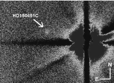
The reduced data for one of the commissioning targets – HD150451AB – revealed a faint detection (see Fig. 14) of the recently identified cool white dwarf companion HD150451C (Carson, 2005). At the time a potential brown dwarf companion was suspected. Since no field rotations were performed to confirm this was not an AO artefact and the signal to noise for the dwarf was extremely low, no specific conclusions could be made as of May 2002. The data collected over 2 years by Carson (2005) has confirmed this to be a companion to HD150451AB, and although initial data suggested the companion to be a methane brown dwarf, recent spectroscopic measurements favour a cool white dwarf classification.
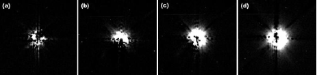
Sky frames were taken for all data (every 10 minutes in K and every 15 minutes in J) to allow more accurate background subtractions. Two different PSF subtraction stars were observed for each target, although with much longer intervals than is ideal due to time constraints. It became apparent that the PSF stability was poor so that subtractions across timescales greater than 5 minutes were contaminated with many AO residuals. Fig. 15 shows this PSF change over time, taken from J-band images of HD141569.
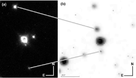
Due to the limited time, nothing of interest was uncovered in data taken on MWC297. However the PSF star chosen for MWC297 revealed a group of 4 stars in close proximity (see Fig. 16(a)), with the closest being 1.6 arcseconds from the central PSF star. No off-mask images were taken for this object since it was originally only to be used as a PSF subtraction star, so only rough estimates of the K-magnitude were possible. The occulted profile was compared to that of an un-masked IR standard star and scaled so that the wings closely matched. This scale factor (corrected for integration time) was then used directly with the IR standard star magnitude and applied to the usual magnitude-flux relation to obtain a value of 8.9. The K-magnitude estimate for the closest star is – a value for the flux contribution from the central star has been subtracted and was estimated by plotting radial averages about the star. The central star and the outermost two stars in this image are listed in the latest Two Micron All Sky Survey (2MASS) catalogue of point sources. This lists BD-04 4476 as having a K magnitude of 8.5 and the outer two stars 12.6 and 11.3 respectively. Taking into account the estimates involved with the focal stop and that 2MASS cannot resolve the inner two stars, our measurements appear to be reasonable.
An upgrade to OSCA was carried out in April 2003. The Gaussian occulting masks were installed along with a razor edged anti-scatter mask in front of the focal plane substrates (to reduce scattering from the edges of substrates on which the occulting spots are deposited). The whole of OSCA was also moved and installed at GRACE (a new, environment controlled laboratory on one of the Nasmyth platforms on the WHT). This should alleviate previous problems of dust contamination and temperature problems for NAOMI.
6 Conclusions
OSCA is a high precision stellar coronagraph, produced on a low budget, over a short timescale and meeting all the design specifications. However, due to the limited time assigned for the commissioning and the overlap with NAOMI engineering schedules, a complete and thorough testing of OSCA has not been possible and as a result there have been no performance tests done with OSCA in optimum seeing conditions and optimum alignment (both of OSCA and other instrumentation).
The mechanics and electronics of OSCA have operated consistently to date and succeed in maintaining the required positioning and alignment, including that for the Lyot stop rotation. The deployment mechanism for OSCA has proven to be very successful; it allows OSCA to be raised in to (and out of) the beam very quickly and with consistently accurate positioning, allowing for a flexible and varied observing program over the course of a night.
Simulations of the NAOMI and OSCA system also have relevance for the next generation of extremely large telescopes where high contrast imaging is essential in the search for extra-solar planets. When designing a coronagraphic system for a highly segmented aperture suitable masking in the Lyot (pupil) plane must be devised to counteract the strong diffraction pattern that will result otherwise - reducing suppression performance and confusing the data.
A number of interesting astronomy targets have been observed during the OSCA commissioning runs. The most positive results were the very faint detection of the cool white dwarf in HD150451 and the discovery of a potential companion (AU) in BD-04 4476. More data is required to draw any firm conclusions on the nature of these objects.
Information regarding the current status of OSCA and instructions for observing with the system can be found on the ING website.
Acknowledgments
In memory of Richard Bingham, who passed away during the publication of this paper. Richard was a great colleague and a brilliant optical designer and will be sadly missed by us all.
We would like to thank the Isaac Newton Group at the William Herschel Telescope for their support during the commissioning of OSCA. We also thank the astronomers at University College London and elsewhere that gave us help and suggestions for observing and objects of scientific interest. The funding for OSCA was provided by the UK Particle Physics and Astronomy Research Council (PPARC). SJT acknowledges PPARC for providing the Ph.D studentship, during which the research for this paper was completed.
This research has made use of the SIMBAD database, operated at CDS, Strasbourg, France
References
- Carson (2005) Carson J.C., 2005, Ph.D thesis, Cornell University, p.107
-
(2)
ING official OSCA webpage,
http://www.ing.iac.es/Astronomy/instruments/osca - Lane (1992) Lane R.G., Glindemann A., Dainty J.C., 1992, Waves in Random Media, IOP, 2, 209
- Lyot (1939) Lyot M.B., 1939, MNRAS, 99, 580
- Malbet (1996) Malbet F., 1996, A & AS, 115, 161
- Murakawa (2003) Murakawa K., Suto H., Tamura M., Takami H., Takato N., Hayashi S.S., Doi Y., Kaifu N. et al., 2003, SPIE, 4841, 881
- Myers (2003) Myers R.M., Longmore A.J., Benn C.R., Buscher D.F., Clark P., Dipper N.A., Doble N., Doel A.P. et al., 2003, SPIE, 4839, 647
- Nakajima (1994) Nakajima T., 1994, ApJ, 425, 348
-
Thompson (2004)
Thompson S.J., 2004,
Ph.D thesis, University College London, ch.3,
http://www.star.ucl.ac.uk/sjt/osca/sjt_thesis2004.pdf - Thompson (2003) Thompson S., Doel, A.P., Bingham, R.G., Charalambous, A., Bissonauth, N., Clark, P., Myers, R.M., Talbot, G., 2003, SPIE, 4839, 1085
- Walter (1996) Walter D., Stein R.D., Long P., Wu C., Lee S.H., 1996, SPIE, 2689, 153