11email: ile@mpe.mpg.de, jcg@mpe.mpg.de, grh@mpe.mpg.de, elisa@mpe.mpg.de 22institutetext: Astrophysikalisches Institut Potsdam, An der Sternwarte 16, D-14471 Potsdam, Germany
22email: tbecker@aip.de, mmroth@aip.de, ssanchez@aip.de 33institutetext: Special Astrophysical Observatory of the Russian AS, Nizhnij Arkhyz 369167, Russia
33email: fabrika@sao.ru, olga@sao.ru, vafan@sao.ru, sura@sao.ru, ban@sao.ru 44institutetext: Department of Physics, Carnegie Mellon University, Pittsburgh, PA 15213, USA
44email: miyaji@astro.phys.cmu.edu 55institutetext: Isaac Newton Institute of Chile, SAO Branch, Russia
Integral field spectroscopy of the ultraluminous X-ray source Holmberg II X-1
We present optical integral field observations of the H II region containing the ultraluminous X-ray source Holmberg II X-1. We confirm the existence of an X-ray ionized nebula as the counterpart of the source due to the detection of an extended He II region (2147 pc) at the Chandra ACIS-S position. An extended blue objects with a size of 1114 pc is coincident with the X-ray/He II region, which could indicate either a young stellar complex or a cluster. We have derived an X-ray to optical luminosity ratio of LL, and presumable it is LL using the recent HST ACS data. We find a complex velocity dispersion at the position of the ULX. In addition, there is a radial velocity variation in the X-ray ionized region found in the He II emission of km s on spatial scales of 2-3. We believe that the putative black hole not only ionizes the surrounding HII gas, but also perturbs it dynamically (via jets or the accretion disk wind). The spatial analysis of the public Chandra ACIS-S data reveals a point-like X-ray source and marginal indication of an extended component ( % of the total flux). The XMM-Newton EPIC-PN spectrum of HoII X-1 is best fitted with an absorbed power-law in addition to either a thermal thick plasma or a thermal thin plasma or a multi-colour disk black body (MCD). In all cases, the thermal component shows relatively low temperatures (kT keV). Finally we discuss the optical/X-ray properties of HoII X-1 with regards to the possible nature of the source. The existence of an X-ray ionized nebula coincident with the ULX and the soft X-ray component with a cool accretion disk favours the interpretation of an intermediate-mass black hole (IMBH). However the complex velocity behaviour at the position of the ULX indicate a dynamical influence of the black hole onto the local HII gas.
1 Introduction
The two main classes of discrete galactic X-ray sources, X-ray binaries and supernova remnants (SNR), have been known and relatively well understood for decades. The third class of galactic X-ray sources was detected with Einstein due to its high spatial resolution and its large collecting area (Fabbiano Fab89). These objects have become known as Ultraluminous X-ray sources (ULX) and they have 0.5-10 keV luminosities of 10 erg s, generally higher than black hole binaries such as Cyg X-1 and SMC X-1, but lower than that of active galactic nuclei (AGN). Assuming Eddington luminosities, this corresponds to accretion onto black holes of masses between ten and several hundred solar masses suggesting intermediate-mass black holes (IMBHs; see Colbert & Mushotzky Col99, Miller & Colbert Mil04 for a review). ULX are not located in the dynamical center of their host galaxies and thus they are not caused by sub-Eddington accretion onto a central AGN-type super-massive black hole. The identification of the optical counterparts of ULX is one of the most important issues to determine the nature of these objects. The number of optically identified ULX is still limited, only a small number of reliable optical counterparts are known to date. Several ULX seem to be associated with H II regions or nebula (e.g., Pakull & Mironi Pak01, Foschini et al. Fos02, and Wang Wa02). However, some ULX have been associated with an accreting black hole in a globular cluster (see Angelini et al. Ang01, Wu et al. Wu02). The optical counterpart to an extremely luminous X-ray source near Holmberg IX is a shock-heated nebula, which is associated with a optically faint non-stellar source (Miller Mil95).
The discovery of the intense He II nebular recombination line in Holmberg II X-1 (hereafter; HoII X-1) indicates that the interstellar medium probably reprocesses part of the X-ray luminosity of erg s. Assuming quasi-isotropic emission (Pakull & Mironi Pak01) and the distance of Mpc, the X-ray luminosity of HoII X-1 corresponds to the Eddington mass of 80 M, which is considered a rather strict lower limit to the mass of accreted compact object if the X-ray emission is isotropic.
A more accurate distance to HoII of 3.39 Mpc was recently determined by Karachentsev et al. (Kar02). The new distance estimate would result in only a minimal difference in the size, flux, and luminosity values we have calculated assuming a value of Mpc.
The ROSAT HRI and PSPC data of HoII X-1 were presented in detail by Zezas et al. (Ze99), revealing a point-like, variable source (on scales of days and years) at the edge of the compact H II region #70 (Hodge, Strobel & Kennicut Ho94). The ROSAT PSPC spectrum was best described by either a steep power-law with or a thermal plasma with keV. Miyaji, Lehmann & Hasinger (Mi01; hereafter MLH01) found that the ASCA spectrum extends to harder energies. The hard part of the spectrum is best fitted with a flatter power-law with and intrinsic absorption above that of our galaxy. A multi-colour disk black body model (MCD, Mitsuda et al. Mit84) did not fit the ASCA spectrum of HoII X-1, unlike some other ULX’s of similar luminosities. A joint PSPC-ASCA spectral analysis showed a soft excess component above the power law component. The soft excess could be described by either a MCD model with keV, or a thin thermal plasma with keV. MLH01 disfavored the MCD interpretation for the soft excess based on the large discrepancy between the black hole mass estimated from and that estimated from the normalization. Furthermore, the spatial analysis of the ROSAT HRI image indicates an extended component.
In this paper we report on optical integral field and long-slit spectroscopic observations of the ultraluminous X-ray source X-1 in Holmberg II, as well as on results from the spatial and spectral analysis of the public XMM-Newton and Chandra data.
The outline of this paper is as follows. The optical imaging, and the long-slit and integral field spectroscopy of HoII X-1 are presented in Sect. 2. The H II region associated with the X-ray source is presented in Sect. 3. The optical properties (e.g., emission line flux maps, velocity dispersion, and radial velocities) of the H II region are described in Sect. 4. In Sect. 5 we present the X-ray spectral and spatial analysis based on public XMM-Newton EPIC-PN and Chandra ACIS-S data. The implications of our results with respect to the nature of the ULX HoII X-1 are discussed in Sect. 6.
| integral field spectroscopy | long-slit spectroscopy | imaging | ||
| telescope | Calar Alto 3.5m | SAO 6m | SAO 6m | CFHT 3.6m |
| instrument | PMAS | MPFS | LSS | OSIS |
| date of observation | 28.10.2001 | 15.03.2002 | 14-15.01.2002 | 11.03.2000 |
| exposure time | 4900s mosaic,- offsets: 4 | 2900s | 1800s (N1-3) | 21200s (H) |
| 2700s (N4-5) | 2300s () | |||
| 2500s () | ||||
| seeing | 1.0 | 1.5–2.0 | 1.5/1.1 | |
| field of view | 88, 1212 (mosaic) | 1616 | 2 | 33 |
| pixel scale | 0.5/pix | 1.0/pix | 0.41/pix | 0.088/pix |
| image size in pixels | 20484096 (binned 22) | 10241024 | 10241024 | 20482048 |
| spectral coverage | 4450-5140 Å | 4210-6820 Å | 4330-6750 Å | - |
| dispersion | 0.76 Å/binned pix | 2.7 Å/pix | 2.4 Å/pix | - |
| spectral resolution | 1.5 Å | 7.0 Å | 7.2 Å | - |
2 Observations and data reduction
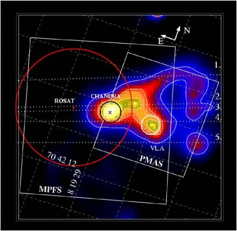
We have carried out integral field observations with the Potsdam Multi-Aperture Spectrophotometer (PMAS; Roth et al. Ro00) and with the Multi-Pupil Fiber Spectrograph (MPFS; Afanasiev et al. Afa95a), and long-slit observation with the Long–Slit Spectrograph (LSS; Afanasiev et al. Afa95b) to determine the nature of the optical counterpart of HoII X-1. These observations are complementary due to the different technical properties of each instrument, e.g.; FOV, pixel scale, and spectral resolution, and due to the observational conditions (see Table 1). Because the accurate Chandra position (see Sect. 5) was not know at the time of our observations, it was especially necessary to cover a large field of view with the integral field technique. Fig. 1 shows the overlays of the FOV for each instrument on the CHFT archival image (see Sect 2.3) of the HoII X-1 region. A detailed description of the observation is given below.
2.1 Integral field spectroscopy with PMAS and MPFS
We have used the PMAS at the Calar Alto 3.5m Telescope to obtain integral field observation of the optical counterpart of HoII X-1. The observations were part of a Science Verification run from October 23-28, 2001. We have observed on Oct. 28 a set of 4 mosaic pointings, each offset by 44 arsec in four different directions from the previous deep field in order to search for spectral signatures which could be associated with HoII X-1.
Motivated by the detection of the He II emission at the edge of the PMAS mosaic FOV (see Sect. 4.1) we conducted further observations with MPFS at the 6-m SAO telescope in Russia. The LSS observations, obtained before the MPFS data (see Table 1), provided valuable insight as to point the MPFS instrument exactly on the He II region. The ”heel” of the foot–like H II region HSK #70 (Hodge, Strobel & Kennicutt Ho94) was centered on the CCD frame during the MPFS observations (Fig. 1).
The PMAS and MPFS data were reduced using P3d, an IDL based data reduction package developed at the Astrophysikalisches Institut Potsdam (Becker Be02). The bias was subtracted using a bias exposure taken at the beginning of each night. Continuum lamp and Mercury (PMAS) or Neon (MPFS) emission line lamp exposures were taken before and after the science exposures. The continuum lamp exposures were used to trace the individual spectra.
The line lamp exposures were used for wavelength calibration. The small number of mercury lines in the PMAS calibration spectra does not allow for a very accurate wavelength calibration. Therefore we have not derived radial velocities from the PMAS data.
The fiber throughput variations were calibrated using a sky flat taken at the end of the night. The absolute flux calibratio of the PMAS and MPFS spectra was obtained using standard star exposure of HR153 and G191B2B, respectively, just before the science exposures.
The PMAS images were combined to a single mosaic frame after correcting for atmospheric refraction (Filippenko Fi82), in each individual exposure.
2.2 Long-slit observations
Observations were carried out with the LSS instrument installed at the prime focus of the 6-m SAO telescope. The slit orientation for the LSS spectra (N1-5) was along the main axis of the foot–like H II region, P.A. (see Fig.1). The relative offsets between the slits N2 and N3, and between the slits N3 and N4, are 0.6 and 1.3, respectively. The slit N1 was offset 3.3 North-East of N2, and the slit N5 was offset 2.5 South-West of N4.
The accurate locations of the slits were determined using images from the TV–guiding camera on the LSS spectrograph. The FOV of the guiding camera is 2. Five stars surrounding the target were used to determine the coordinates of the slit in each image.
We have use standard MIDAS procedures to reduce the LSS spectra. The wavelength calibration was checked again using the [O I] and sky lines.
2.3 CFHT archival imaging data
We adopted the accurate Chandra coordinates and applied linear astrometry to the CFHT , , and archive images to determine the position of the X-ray source in the H II region.
For an absolute photometric calibration two images of the globular cluster NGC4147 taken during the same night were utilised. Six standard stars from the cluster (Odewahn et al. Ode92) were used to calibrate the images. The calibration was double checked by independent measurements of the comparison stars in B-band CCD images made by V. Goranskii with the 1-m SAO telescope.
3 Optical counterpart of the ULX HoII X-1
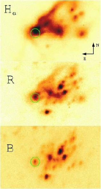
To obtain a reliable astrometry of the CFHT , and archival images we used the USNO-B1.0 catalogue. The astrometric accuracy of the catalogue is about 0.2 at J2000. About fifteen USNO-B1.0 stars were found within the OSIS FOV around HoII X-1. The standard deviations of the star positions are 0.20 for the , 0.13 for the , and 0.15” for the images. In Fig. 2 we present the CFHT images with the Chandra ACIS-S source position marked (see detailed description in Sect. 5). An object on the image perfectly coincides with the position of the X–ray source. Its magnitude is mag.
Since all the stars on the image in Fig. 2 look elongated, while the seeing was fairly good (”), we fitted 2d-Gaussians to 23 stars surrounding the X-ray position. The elongation of these stars was , where the major axis size is ” and the minor axis is ”. The position angle of the star images was P.A..
The object coincident with the X-ray source has the following parameters: , ”, ” and P.A., which indicates that in comparison to the surrounding stars the counterpart is an extended object, e.g. a nebula or a compact stellar cluster. Its intrinsic size is about 0.69 (11 pc) in the West-East direction and about 0.85 (13 pc) in the North-South direction. The orientation is P.A..
Assuming the -band flux calibrations from Allen (All73), and a line-of-sight extinction to HoII of (Schlegel et al. Schl98), the optical luminosity of the counterpart is estimated to be erg/s. The absolute magnitude of this object is . Using the X-ray luminosity in the 0.3-8.0 keV energy band of erg/s, corrected for absorption (see Sect. 5.2), we find . Recent HST ACS observations of HoII X-1, (published after the submission of this paper), resolved this object into several young stars (Kaaret et al. Kaa04), which agrees with our interpretation. Due to the superb angular resolution of the ACS images Kaaret found a bright, point-like optical counterpart consistent either with a star with spectral type between O4V and B3 Ib, or reprocessed emission from an X-ray illuminated accretion disk. Because the star found by Kaaret et al. (Kaa04) is about one magnitude fainter compared to our extended blue counterpart this results in a of .
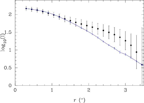
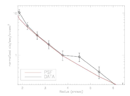
The MPFS He II line flux map (see Fig. 6 in Sect. 4.1) clearly shows a He II emission line region at the Chandra ACIS-S position, and coincident with the optical counterpart detected on the CHFT image. This confirms the classification of ULX HoII X-1 as an X-ray ionized nebula (Pakull & Mirioni Pak01). In order to determine if the He II emission is extended we have derived the surface brightness profile of the He II region, using an algorithm based on Jedrzejewski (Jed87). This method increases the signal-to-noise in the outer part of the surface brightness profile, since it comprises an average of the brightness along the eccentric anomaly. A similar technique is extensively used for the detection of host galaxies in QSOs (eg., Sánchez & Gonzalez-Serrano San03).
The MPFS PSF was built using the continuum emission at a wavelength range near the He II emission. Fig. 3 shows the surface brightness profile of the He II region together with the surface brightness profile of the PSF, scaled to the peak of the He II emission. The He II emission is clearly extended beyond r2, which is also confirmed by the HST ACS He II narrow band image of Kaaret et al. (Kaa04).
We find an extended and elongated He II region with nearly the same positional angle of P.A. as found for the blue counterpart on the image. The size of the He II region after PSF correction is about 1.4 3.0 (see Fig. 3), which corresponds to about 21 47 pc. The larger size of the He II region compared with the blue counterpart (1114 pc) could be considered as an argument for a stellar complex, where the -band counterpart represents the continuum emission and the He II region represents the high excitation nebula.
The most important observational results from this section are that the He II emission is: extended, and in the same positional angle as the extended blue counterpart, and centered on the X-ray source. This confirms the classification of HoII X-1 as an X-ray ionized nebula as suggested by (Pakull & Mirioni Pak01).
4 Emission line properties
To determine the physical parameters (e.g. the radial velocities and the velocity dispersions) of the H II region associated with the ULX, we have measured the emission line properties of all lines in the LSS, PMAS and MPFS spectra. Whereas the PMAS spectra cover only the He II , H and the [O III] emission lines, the MPFS spectral range includes the H and H emission line regions as well.
Each emission line in the 240 MPFS and 506 PMAS integral field spectra was fitted with a Gaussian profile applying the Levenberg-Marquardt algorithm (Press et al. Pre92). The four adjustable parameters were the total line flux, the mean wavelength, the sigma width of the Gaussian, and the flux of the local linear continuum. The Levenberg-Marquardt algorithm also estimates one-sigma errors for each parameter. We considered only the emission line parameters of those lines which were at least 5 detections in the PMAS spectra, or 3 in the MPFS spectra. We have visually checked the reliability of the chosen line detection thresholds for the each spectrum.
4.1 Line fluxes and He II line luminosity
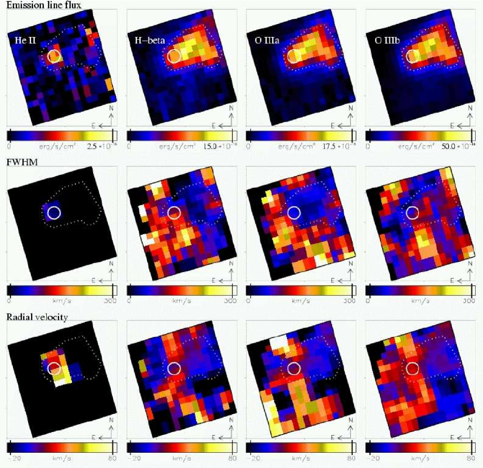
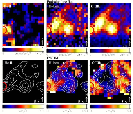
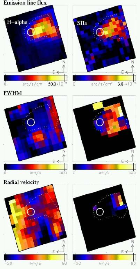
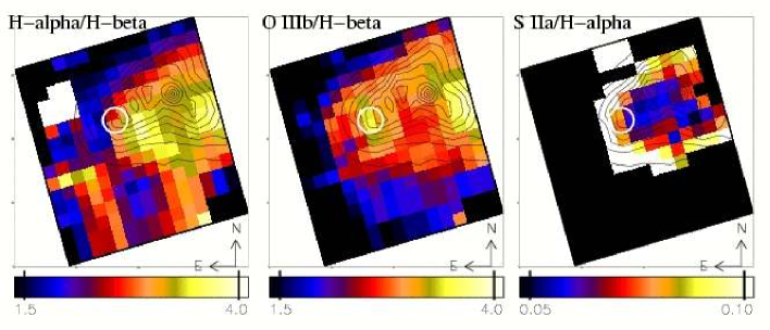
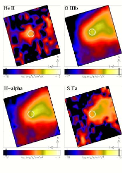
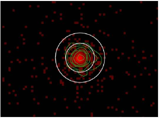
The emission line flux maps of H and [O III] derived from the PMAS mosaic spectra, and of He II, H, [O III] , H and [S II] derived from the MPFS spectra, are presented in the upper panel of Fig. 4, 6 and 7. The linear flux scale given below the maps starts with the blue color. The black regions mark the non-detection of a 5 sigma line for PMAS spectra and of a 3 sigma line for MPFS spectra. The circle with 1 radius marks the X-ray position determined from the Chandra ACIS-S data (see Sect. 5).
Because the PMAS data were taken under better seeing conditions and due to the better angular sampling of PMAS (see Table 1), the PMAS emission line flux maps of H and [O III] show more details compared to the MPFS maps. For instance the peak of both lines in the MPFS data is clearly resolved into two clumps with PMAS.
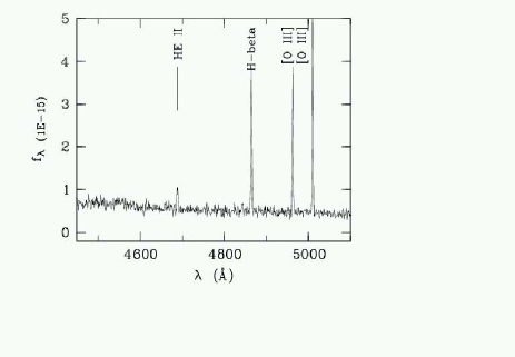
He II emission lines are clearly detected from a relatively compact region inside the H II region #70 at the Chandra ACIS-S position (see Fig. 6). He II emission lines are not detected in the individual PMAS spectra due to the short exposure time. However, the He II line is clearly seen in the co-added PMAS spectrum (see Fig. 5). In addition, the co-added spectrum suggests of an increasing blue continuum at wavelength below 4700 Å, which is probably produced by the young stars resolved with HST. The increasing continuum to the blue is seen as well in the LSS spectrum (see Fig. 8). The absolute continuum flux of the PMAS and LSS spectra are not comparable because of the different amount of sky background emission. Nevertheless, the increasing blue continuum cannot be explained by the sky background.
The fluxes of all but the He II emission lines peak outside the X-ray error circle (see Fig. 6 and 7). The peak PMAS fluxes agree well with the peak MPFS fluxes.
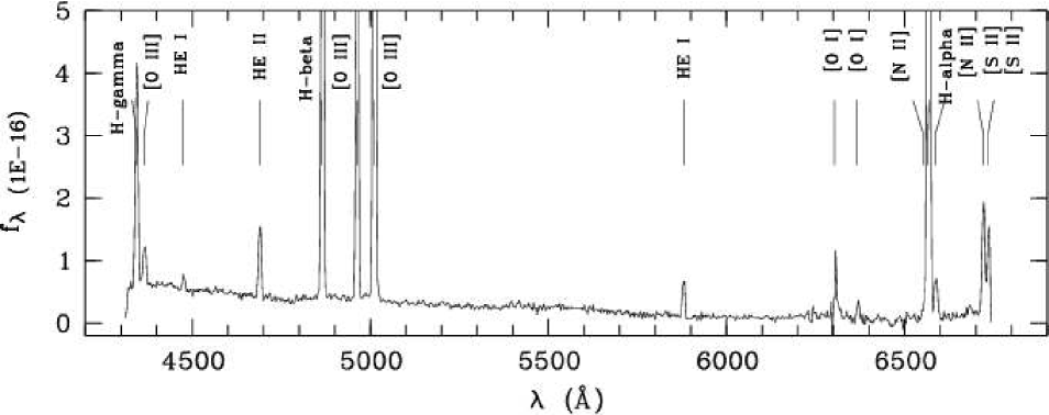
In Fig. 8 we present an averaged LSS spectrum of N2 and N3 at the location of the blue extended counterpart. This spectrum covers the brightest region in He II; however, the spectrum did not cover the region completely. The real flux could be a factor of times larger. The brightest lines in the spectrum are the hydrogen lines and [O III] . No notable absorption lines or broad wings in the permitted lines are observed; however the faint blue continuum is clearly seen. All significantly detected lines are narrow, and formed in the nebula. He II emission is the strongest permitted line (after the Hydrogen lines) indicating a high excitation of the X–ray ionizated nebula (XIN, Pakull & Mirioni Pak01).
Relative intensities of emission lines in the LSS spectra agree very well with those from the MPFS/PMAS spectra, however they are slightly different in individual LSS-spectra. The latter implies that the physical conditions of the gas may be different in different parts of the XIN. The relative fluxes of the MPFS spectra and the averaged LSS spectra N2 and N3 in units of the H flux are given in Table 2.
From the He II flux map in Fig. 6 we have determined a total line flux of 1.55 10 erg s cm corresponding to a luminosity of erg s. Using the averaged LSS spectra N2 and N3 at the X-ray source position we have determined a total He II luminosity of erg s, where the He II equivalent width is 29.7 Å. Furthermore, we have estimated the total He II flux from the monochromatic MPFS images in Fig. 10. Assuming an 5” 5” area of the He II region (not PSF corrected) we can directly measure the mean flux of log f, which gives a luminosity of erg s. The total H luminosity in our LSS data is L(H erg/s.
The He II luminosity agrees with the results published by Pakull & Mirioni (Pak01) of L(He II) erg/s, and by Kaaret et al. (Kaa04) of L(He II) erg/s (keeping in mind that our long-slits do not cover the entire He II region).
4.2 Diagnostic emission line flux ratios
In order to understand the nature of the ionization inside the H II region # 70 we determined the emission line flux ratios from the LSS and MPFS data. Table 3 gives the diagnostic ratios derived from the averaged LSS at positions N2 and N3 (see Fig. 8). The MPFS line ratio maps of [O III] /H, [S II] /H, and H/H are shown in Fig. 9.
The diagnostic line flux ratios (O III/H, O I/H, N II/H, and S II/H see Table 3) derived from the averaged LSS spectrum and the MPFS line ratio maps agree well with the H II region classifications (Veilleux & Osterbrock Vei87). The N II/H ratio is at the lower end for H II regions (see Fig. 12.1 in Osterbrock Ost89).
The line flux ratio of [S II] /H is well below 0.4 (see Table 3), which is an indication that emission comes from ionized gas in H II regions or in a nebula rather than from supernova remnants (Smith et al. Smi93). The 6, 20, and 90 cm radio data from Tongue & Westpfahl Ton95) shows a peak at the position: 8 19 28, 70 42 19 (J2000), which is about 3 West of the Chandra position (see Fig. 1). However, due to the low angular resolution of the data () the radio position is not precise enought to exclude a coincidence with the X-ray source. While the steep radio spectral index of (between the 6 and 20 cm wavelength bands) favours supernova remnants (SNR) as the source of the radio emission, the optical emission line ratios suggest that the region of the radio emission is instead a H II region.
The MPFS line ratio maps of [O III] /H and [S II] /H in Fig. 9 show no large variation over the H II region. Inside the Chandra ACIS-S error circle and inside a region 10 North-West of that position the MPFS flux ratio map shows slightly larger values of the [O III] /H ratio () compared to for the main parts of the H II region (), which could indicate a slightly larger ionizating level in these regions.
The H/H flux ratio map corrected for differential refraction (Fig. 9) shows a peak () about 3 South-West of the X-ray position and a second peak () about 10 West of the Chandra position. The remaining parts of the H II region have a ratio of 2.4–2.9. The second peak is positionally consistent with the peak in the [O III] /H flux map. Interestingly, the H II region # 70 seems to be much more extended to the South indicated by the red features in the lower panel of the flux ratio map.
To determine the intrinsic flux ratio of the H II regions we used the case B Balmer recombination decrement f/f for K and N cm (Brocklehurst Bro71). Assuming that the observed H/H ratio inside the H II region is due to extinction we obtain for when the ratio is 2.9 and when the ratio is 3.6. In this case the H II region would show a larger extinction at about 3 South-West of the X-ray position and at about 10 North-West of the X-ray position. However, the larger H/H ratio in these regions could even be due to larger ionization.
| line | relative flux | |
|---|---|---|
| LSS | MPFS | |
| H | 0.45 | - |
| O III | 0.08 | - |
| He I | 0.08 | - |
| He II | 0.14 | 0.12 |
| He I | 0.01 | - |
| He I | 0.01 | - |
| O III | 1.00 | 1.20 |
| O III | 3.00 | 3.00 |
| He II | 0.02 | - |
| He I | 0.07 | - |
| O I | 0.11 (0.03) | - |
| H | 3.20 | 3.80 |
| N II | 0.08 (0.02) | - |
| He I | 0.03 | - |
| S II | 0.22 (0.07) | 0.28 |
| nr. | ratio | value |
|---|---|---|
| 1 | O III/H | 0.48 |
| 2 | O I/H | -1.52 |
| 3 | N II/H | -1.69 |
| 4 | S II/H | -0.93 |
| 5 | S II/S II | 0.10 |
| 6 | O III/O III | |
| 7 | H/H | 0.51 |
Following Osterbrock (Ost89) the line flux ratio [S II] /[S II] was used to determine the electron density of region # 70, which is about 200 cm. This value is typical for H II regions. The temperature of the H II region of T15000 K has been estimated from the line flux ratio [O III] /[O III] (Osterbrock Ost89).
The main result of this section is that the emission line flux ratios inside the Holmberg II region #70, even at the positions of the X-ray and radio sources, are consistent with H II regions.
4.3 FWHM of emission lines
In order to search for dynamical signatures of a black hole we determined the FWHM of the emission lines. The main problem is to correct the observed FWHM for instrumental resolution, which depends on the single pixel and the wavelength positions. We have derived the instrumentally corrected FWHM using the FWHM of the night sky lines and the FWHM of the emission lines from calibration lamp exposures. However, we cannot account for all instrumental effects, and these becomes especially significant for the lower resolution MPFS data.
The PMAS FWHM maps and the MPFS FWHM maps (in km s) are presented at the bottom of Fig. 4 and in the middle of Fig. 6 and 7, respectively. The color scale of the FWHM images was chosen to show reliable structures of the velocity field. Due to the larger angular sampling (0.5/pix) and the better spectral resolution the PMAS spectra are better suited to derive the FWHM of the lines. Unfortunately, the PMAS spectra show that the He II /O III emission region, and the PMAS mosaic do not cover the entire Holmberg II region #70.
The lower panel of Fig. 4 shows that the PMAS FWHM of the H line inside the H II region is in general larger compared to that of the forbidden [O III] line. The PMAS FWHM of both lines peak around the position of the Chandra ACIS-S error circle.
Because the PMAS and MPFS FWHM maps are given with different scales we present for comparison the peak values of the FWHM inside the H II region derived from both intruments in Table 4. The MPFS FWHM peak values are in agreement with those values derived from PMAS (keeping in mind the lower angular and spectral resolution of the MPFS data), except for [S II] , which is probably blended with the [S II] emission line. The FWHM of H derived from PMAS reaches about 30 km s inside the H II region, but outside the He II sub-region, it is up to 80 km s. The FWHM of the 30 km s inside the H II region (which translates into a velocity dispersion of about 13 km s), is consistent with the velocity dispersion measurements of km s and km s obtained by Hippelein (Hip86).
However, the FHWM more than doubles at the X-ray position. Assuming the virial theorem and that the enclosed mass is related to the velocity change of 50 km s at the distance of 30 pc the resulting mass of a putative black hole would be about M. Therefore we believe that the increased FWHM at the location of the He II/X-ray source may be understood as dynamical influence of the putative black hole like the accretion disk wind or jets.
The MPFS FWHM maps show a very complex velocity field in the South-East direction of the Chandra position, but outside the main H II region. Furthermore there is a peak of km s at about 5 South-West of the X-ray source position in the MPFS FWHM maps of H, [O III] , and H. The complex velocity field outside the H II region is most probably not related to HoII X-1.
| emission line | FWHM | |
|---|---|---|
| PMAS | MPFS | |
| He II | - | km s |
| H | (30) km s | km s |
| O III | - | km s |
| O III | km s | km s |
| H | - | km s |
| S II | - | km s |
- Peak value inside the H II but outside the He II region.
-
Probably blended with [S II
.]
4.4 Radial velocities
To determine the radial velocity field around HoII X-1 we have used the LSS spectra at the slit positions N2 and N3 and the MPFS data.
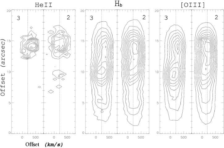
In Fig. 11 we show the continuum and background subtracted line isophotes of the 2d-LSS spectra in the He II emission line. The position of the emission line (or equivalently, the position of the line emitting region) along the wavelength direction (accros the slit) is given as an offset in km s. The position along the slit is given as an offset in arcsec, where East edge of the ”heel” of the compact H II region #70 is located at an offset of and the He II region at an offset of . The offset values decrease in the North-West direction. Both spectra N2 and N3 cover HoII X-1. The He II peak intensity in N2 is 1.4 times greater than that in N3.
The He II region is located near the edge of the H II region. Along the slits we can directly study the structure of the region and we can see the complex structure of the He II emission. Even the shift in the slit position from N2 to N3 (0.6) results in a notable change of the isophote structures.
The line isophote structures across the slits can not be directly interpreted as radial velocity variations, because the slit width (2) is larger than the seeing. In the isophotes shown in Fig. 11, the redshift corresponds to a shift of an emission knot covered by the slit to North-East direction.
There is an additional He II emission region, which is located about 6–7 ( pc) in North-West direction of the the He II/X–ray source (see Fig. 6 and 10). The same He II emission region is detected in the spectrum N2. The CFHT archival image in Fig. 2 shows that this is very complex region. It may be that the He II emission is radiated by Wolf-Rayet stars.
In considering the radial velocity distributions in Fig. 11 we have to remember that the absolute values of the velocities are not correct as they depend on the emission knot location within the slit. The complex structure of the radial velocity field is more obvious in the MPFS radial velocity maps at the bottom panel of Fig. 6 and 7. The radial velocity maps of the strong emission lines, H, [O III] and [O III] (except of H), show nearly the same structure in the H II region and its enviroment. The radial velocity ranges from about -20 to 40 km s inside the H II region, and reaches its maximum around the position of the X-ray source. Crossing the Chandra position nearly in East-West direction (see the maps of H to [O III] in Fig. 6) the radial velocity changes from negative to positive to negative. The behaviour is comfirmed by the radial velocities derived from the LSS spectra N2 and N3. If we assume a line crossing the Chandra position im North-South direction the radial velocity shows only positive values.
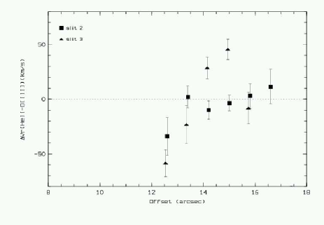
As already found for the MPFS spectra, the H and [OIII] radial velocities derived from the LSS spectra are absolutely the same. Because the LSS spectra have higher S/N we can study the radial velocity field much better. The LSS spectra show that there is a difference in the He II and [O III] radial velocities inside the He II region (see Fig. 12). Moving along the slit N2 from the ”heel’s” edge (offset position )) toward the main nebula in North-West direction, the He II line shows about the same velocity as the [O III] line, but it becomes negative (–30 km s) at the offset position of 12–13. Along the slit N3 the He II behavior is more complex. Its relative radial velocity is about zero at the ‘heel’s” edge, positive (up to km/s) in the middle of the He II region, and negative (–50 km/s) at the offset position of 12–13.5 (North-West of the ”heel”). The maximal differences in the radial velocity of the He II line compared to the [O III] line is km s on spatial scales of ( pc in projection) .
There is a complex radial velocity structure, which may be related to the X-ray source ionizing the surrounding gas. In this case the putative black hole not only ionize the surrounding gas, but also perturb the gas dynamically.
5 Chandra and XMM observations of HoII X-1
| Detector/Modes | Observation | Exposure/Frame |
|---|---|---|
| Chandra ACIS-S | Date: 02-NOV-2001 | 5.1 ks |
| Faint/Timed | Seq. 600121 | 1/4 Subarray |
| XMM PN | Date: 10-APR-2002 | 5.1 ks |
| Thin | Seq. 0112520601 | PrimeFullWindow |
| XMM PN | Date: 16-APR-2002 | 11.1 ks |
| Thin | Seq. 0112522201 | PrimeFullWindow |
| XMM PN | Date: 18-SEP-2002 | 5.0 ks |
| Thin | Seq. 0112520901 | PrimeFullWindow |
A 5.1 ks Chandra observation of this object was done with the ACIS-S detector. The data were obtained from the public archive and a spectral and spatial analysis was carried out. The log of the Chandra and XMM observations is shown in Table 5. Because of the superb spatial resolution of Chandra, we were able to locate HoII X-1 with much better accuracy than previous observation with ROSAT HRI (MLH01). A two-dimensional Gaussian fit of the Chandra image gives the position of HoII X-1 as RA: 8 19 29.0, DEC: +70 42 19 (J2000). The ROSAT HRI position of RA: 8 19 29.7 and DEC: +70 42 18 (J2000.0) agrees well within its uncertainties (Colbert & Mushotzky Col99).
Because there are no X-ray sources in the Chandra FOV which can be unambiguously identified with an optical/radio counterpart, the positional accuracy is limited by aspect uncertainties in the Chandra pointing. This is roughly estimated to be 1, which we take as the radius of the positional error circle (Fig. 1).
Three XMM observations of HoII X-1 were made with the EPIC PN/MOS detectors (see Table 5). A total of 14.9 ks of good EPIC PN data were obtained after correcting for background flares. A combined events file was derived from the individual events files of the different exposures. The XMM EPIC PN position of RA: 8 19 29.1 and DEC: +70 42 19 (J2000.0) is in good agreement with the ACIS-S position.
As already mentioned Tongue & Westpfahl (Ton95) have detected a radio peak at 6, 20 and 90 cm wavelengths at the position 8 19 28, +70 42 19 (J2000.0). However, due to the low angular resolution of the radio data, it is not clear whether the radio emission offset from the X-ray position is coincident with the X-ray source.
5.1 Spatial analysis
In Fig. 13 (left panel) we compare the radial profile of HoII X-1 with the ACIS-S Point Spread Function (PSF) at 1 keV, where the peak of the source flux lies. The PSF was created using the pre-calculated profiles available in the CIAO package (ver. 3.0) and normalized to the radial profile of the source at the first annulus outside 3, due to heavy pile up in the central region. The 0.5-6 keV source profile was extracted avoiding possible serendipitous sources and the readout streak in the image. The background level was evaluated from an annulus with innnerouter radius of 35, respectively. A hint of extended emission is detected between 4-6 from the source (also emphasized in Fig. 13 (right panel), where a possible Westward extinction is evident. An upper limit on the contribution of the extended component to the total flux is estimated to be %. This value is a qualitative estimation of the extended component, since the pile up introduces an error . A longer exposure would be necessary to put a tighter constraint on the possible extended emission.
5.2 Spectral Analysis
Here we present a first spectral analysis of the XMM-Newton public data. A more detailed analysis is provided in the following paper by Dewangan et al. Dew04.
The EPIC-PN spectrum of HoII X-1 was extracted from a circular region of 150” in radius and the background spectrum was obtained from a nearby source free region. For both spectra we use the combined events file from all three observations (see Table 5). Firstly, we fitted a single power-law and neutral absorption [fit (A)] to the PN spectrum in the energy range from 0.3-10 keV. This gave a fair fit with a power-law. The fit parameters are shown in the first entry of Table 6. An obscured single black body, multi-colour disk black body (MCD), and thermal Bremsstrahlung models gave an unacceptable fit ().
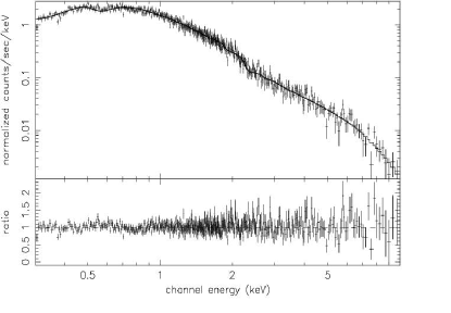
The fitted spectrum is steeper than that found in our previous analysis of the ASCA data, which gave . In our previous analysis, however, we found a soft excess component in the joint spectral fit using ASCA and ROSAT data (MLH01). The best fit model to the ASCA and ROSAT data was a keV thermal plasma, or a keV disk-blackbody, in addition to a power-law. We have applied these models to the EPIC PN spectrum (see Fig. 14) and found that the fit improved significantly. Thus, we consider our previous finding of at least two spectral components in HoII X-1 confirmed. The results of the power-law plus thermal fits [fit (B)] are also shown in Table 6. The thermal component is clearly soft (see Fig. LABEL:fig:uxfit) and contributes about 18 % to the total 0.3-8.0 keV flux. A power-law fit to the soft component is ruled out ( for 476 d.o.f.).
An absorbed power-law and a multicolor disk black body (model C in Table 6) gives a good fit as well. This means that the soft component can be as well described by a MCD model. The inner disk temperature is quite low ( keV), which indicate a cool accretion disk. Soft components with a cool accretion disks may indicate intermediate-mass black holes with a black hole mass of M (Miller et al. Mil03).
| Model | Parameters |
|---|---|
| PLAbs. | ; |
| (A) | |
| PL+Thermal (bbody) | ; ; |
| Abs. | ; |
| (B) | ; |
| ; | |
| PL+Thermal (diskbb) | ; ; |
| Abs. | ; |
| (C) | |
| ; | |
| PL+Thermal (mekal) | ; ; |
| Abs. | ; ; |
| (D) | ; |
| ; | |
| PL+Thermal (mekal+ | ; ; |
| bbody)Abs. | ; ; |
| (E) | ; |
| ; | |
| ; | |
| ; | |
Fit parameters are shown with 90% errors (). The model and parameter definitions are: Model Components– PL: Power-law with a photon index of and a 0.5-2 keV flux of in units of 10 erg cm s. Thermal – thin plasma: Thermal plasma using the XSPEC mekal model with a plasma temperature [keV], a metal abundance in solar units, and the normalization defined by XSPEC . Thermal – multi color disk: The multicolor disk (Mitsuda et al. Mit84) distributed as the XSPEC model (diskbb) with an inner disk temperature and with an normalization defined as , where is the inner disk radius and is the distance to the source in 10 units, and is the viewing angle of the disk axis. Thermal – thick plasma: Thermal thick plasma using the XSPEC bbody model with a plasma temperature [keV], with a normalization defined as L/D, where L is the source luminosity in units of 10 erg s and D is the distance to the source in units of 10 kpc. Abs: Absorption by neutral gas using the XSPEC model wabs (Morrison R. McCammon D. 1983, ApJ 270 190) with hydrogen column density .