Further author information: (Send correspondence to P.M., S.E.P.)
P.M.: E-mail: pmartini@cfa.harvard.edu, Telephone: 1 617 496 1809
S.E.P.: E-mail: persson@ociw.edu, Telephone: 1 626 304 0235
PANIC: A Near-infrared Camera for the Magellan Telescopes
Abstract
PANIC (Persson’s Auxiliary Nasmyth Infrared Camera) is a near-infrared camera designed to operate at any one of the /11 folded ports of the 6.5m Magellan telescopes at Las Campanas Observatory, Chile. The instrument is built around a simple, all-refractive design that reimages the Magellan focal plane to a plate scale of 0.125′′ pixel-1 onto a Rockwell 1024x1024 HgCdTe detector. The design goals for PANIC included excellent image quality to sample the superb seeing measured with the Magellan telescopes, high throughput, a relatively short construction time, and low cost. PANIC has now been in regular operation for over one year and has proved to be highly reliable and produce excellent images. The best recorded image quality has been FWHM.
keywords:
Infrared, Imagers, Astronomical Instruments1 Instrument Overview
Considerable interest in the rapid development of a near-infrared (NIR) camera for the Magellan Project was generated after first light for the 6.5m Magellan I (Walter Baade) telescope in September 2000. The main requirements included excellent image quality to sample the superb seeing observed at Magellan, high-throughput, and a simple design that could be completed relatively quickly. In addition, the instrument was envisioned to eventually occupy one of the folded ports (formerly known as auxiliary Nasmyth ports) and thus remain available for use at all times.
The ready availability of the camera during any observing run was motivated by one of the science goals: time-critical observations of temporally variable objects, such as supernovae and gamma ray bursts. Scientific interests of astronomers at the Carnegie Observatories and other members of the Magellan consortium included follow-up observations of interesting objects discovered in wide-field infrared surveys on smaller telescopes, high-redshift quasars and clusters of galaxies, counterparts to Galactic X-ray sources, and searches for the galaxies responsible for quasar absorption systems.
These science goals led to PANIC (Persson’s Auxiliary Nasmyth Infrared Camera), an all-refractive, m camera that reimages the input beam of the 6.5m Magellan telescopes to produce a plate scale of pixel-1 on its Rockwell HAWAII HgCdTe focal plane array (1024x1024 18.5 m pixels). Use of a compact, all-refractive design and adoption of the electronics and control software from the recently completed wide-field, NIR camera WIRC[1] minimized development costs and led to a relatively short construction time.
2 Optics
The optical design was optimized to critically sample the best images produced by the Magellan telescopes. Typically, these telescopes produce images of or better at visible-wavelengths and a plate scale of pixel-1 was chosen to sample the expected image quality at near-infrared wavelengths. The principal and folded ports of the Magellan telescopes are designed to be fed by the Gregorian secondary mirror, which produces a focal plane scale of mm per arcsecond. PANIC reimages the telescope focal plane from to and produces a field of view.
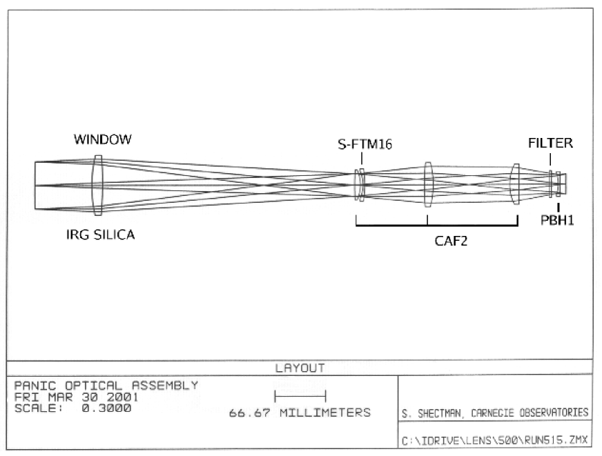
Two other key considerations for the optical design were high-throughput in a compact design and a relatively warm temperature for the camera optics support structure of 200 K (compared to 77 K more typical of NIR instruments). The significant cost savings and ease of construction associated with a smaller instrument motivated an all-refractive design. The glasses used include IR-grade fused silica, CaF2, PbH1, and the O’Hara glass S-FTM16, where the latter was chosen because it forms an excellent infrared achromat with CaF2. IR-grade fused silica was chosen for the vacuum window because of its excellent durability. One key advantage of the warmer optical elements lies in reduced uncertainty in the refractive indices, particularly S-FTM16. The refractive indices for S-FTM16 and PbH1 at 200 K and 77 K, respectively, were calculated with a temperature-dependent refractive index model[2]. This model adds temperature-dependent terms to the common Sellmeier dispersion formula and successfully reproduces the measured temperature-dependent dispersion for CaF2, among other materials. There are also mechanical and thermal advantages discussed below in sections 3 and 4.
The optical design is listed in Table 1 and shown in Figure 1. The all-spherical optical elements were manufactured by Janos Technology Inc. The design produces an rms spot radius of 3 m on axis and better than 4 m images at the edges of the field. Because the field lens, which serves as the vacuum window of the dewar, is not an achromat the position of the pupil image is mildly wavelength dependent. Since the cold stop is most critical for masking thermal radiation from the telescope structure surrounding the secondary mirror, the fixed cold stop in PANIC was positioned and sized for the red end of the NIR filter at approximately 2.3 m, the wavelength region where thermal radiation is most significant. Another trade off in this simple design is the lack of a well-collimated beam, which precludes addition of a grism for spectroscopy.
 |
| Element | Surface | Radius | Thickness | Material | Diameter |
| PAN1 | 1 | 192.35 | 14. | IR-grade Fused Silica | 80 |
| 2 | -551.55 | 336.5 | |||
| PAN2 | 3 | 414.16 | 7.514 | CaF2 | 40 |
| 4 | -50.82 | 3.5 | |||
| PAN3 | 5 | -48.248 | 2.5022 | S-FTM16 | 43 |
| 6 | -137.83 | 69.7 | |||
| PAN4 | 7 | 437.512 | 11.521 | CaF2 | 59 |
| 8 | -115.39 | 111.4 | |||
| PAN5 | 9 | 64.2 | 12.022 | CaF2 | 54 |
| 10 | -4044.36 | 54.130 | |||
| PAN6 | 11 | -42.333 | 2.004 | PbH1 | 33 |
| 12 | 321.741 | 8. |
3 Mechanical Design
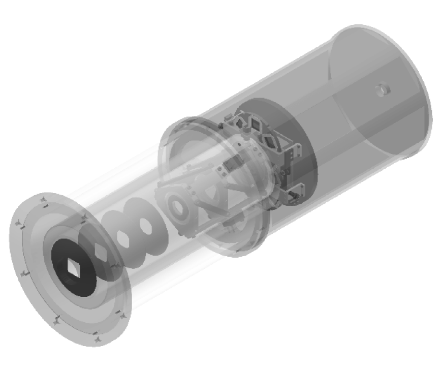
The mechanical design is centered around support for the optical elements and the requirement to minimize flexure, which would produce element tilt and decenter during rotation about the optical axis. Elements 2–5 are supported in a space frame built of Invar, which was chosen for its low thermal expansion properties. This Invar space frame (ISF) is mounted in a stainless steel ring. This ring is rigidly supported by an aluminum tube that connects it to the front mounting surface and also serves as the vacuum enclosure. The mechanical layout is illustrated in Figure 2 (note that the outer aluminum tube is not shown). Finite element analysis demonstrates less than 2 m lateral deflection between the focal plane and ISF at Nasmyth, less than 1 m between the field lens and ISF, and less than tilt. These deflections and tilts are well within the allowances of the optical design. The liquid nitrogen (LN2) reservoir is a model ND-10 dewar from Infrared Laboratories and is also bolted to the stainless steel ring. This dewar has a capacity of 15 liters.
 |
3.1 Optical Mounts
The mounts for optical elements two through five are supported by the ISF described above. The ISF includes one Invar support frame for the closely-spaced elements two and three, and additional, separate supports for elements four and five. These support frames hold separate lens mounts for each of the elements, where the lens mounts are built from materials chosen to have comparable thermal expansion properties to the lenses. For the CaF2 elements, the aluminum alloy 206.0-T7 provides a good match, while titanium provides a good match to S-FTM16. A thin layer of paper lines each lens mount in order to provide an additional buffer against thermal and mechanical stresses. Thermal contact points between the lens mounts and the ISF were also minimized to insure that the mounts and the lenses cool radiatively, which further alleviates stress on the optical elements. The mount for element six, which serves as a field flattener, is incorporated directly into the detector mount.
3.2 Filter Wheels
There are two, six-position filter wheels in PANIC. One of these wheels is populated with , , , and broadband filters; the remaining two are open and dark positions. The second wheel contains two 1% narrowband filters centered at 2.12 m ( 1-0 S(1) line) and 2.16 m (Br), although their presence in a converging beam broadens the passband. They are nevertheless useful for morphological studies of emission-line regions. A series of medium-band filters are planned for the remaining open wheel positions. The filter wheel mechanisms are bolted directly to the work surface of the dewar immediately above the detector mount and field flattener. The wheels cool conductively to nearly 77K.
The filter wheel positions are changed by external stepper motors, which are coupled through the dewar walls with feedthroughs from Ferrofluidics (now Ferrotec). These feedthroughs are thermally isolated from the wheels with G-10 insulators and additional radiation shields. The internal gears for the wheels are mirrored outside the dewar and drive an encoder barrel, which is used to provide an absolute reference for each filter position. Two microswitches inside the dewar are used to determine if the wheels are in one of the spring-loaded detent positions. These detents insure that the filter positions are exactly reproducible.
4 Thermal
One important simplification of the PANIC design was the decision to limit the upper wavelength range of the instrument to the red end of the filter at 2.32 m, a decision which significantly reduces the thermal requirements for the instrument. Calculation of the relative thermal emission from the window and the remainder of the instrument showed that at an internal temperature of 200 K the instrument was still an insignificant contributor to the background through the filter. This operating temperature of 200 K, rather than near the LN2 temperature of 77 K, results in the less stringent optical and mechanical requirements discussed previously, as well as more rapid thermal cycling of the instrument.
However, the decision to maintain most of the instrument at 200 K did necessitate careful attention to thermal stability to both insure that the optics would remain at their designated temperature and to minimize any variations in the instrumental background. Thermal stability was achieved in two steps using both passive and active methods: First, the thermal and conductive loads on the radiation shield and ISF were calculated and tuned to produce an equilibrium temperature of approximately 200 K. These temperatures were coarsely tuned by wrapping the outside of the radiation shield with multiple layers of aluminized Mylar and applying space-qualified black paint to the optical baffles and ISF. The temperatures were then adjusted more finely with two heat switches incorporated into the dewar by Infrared Laboratories. The heat switches were used to separately regulate the degree of thermal conductivity between the LN2 reservoir and both the radiation shield and ISF. A LakeShore 321 Autotuning Temperature Controller is then used to actively maintain the temperature of the ISF at precisely 200 K through a feedback loop between the heater and a temperature sensor, both located on the exterior of the ISF.
We employ a LakeShore 218 Temperature Monitor to continuously monitor eight temperature sensors located on the detector mount, ISF, and radiation shield. The temperature sensor on the detector mount is also used to monitor the cooldown rate of the detector relative to Rockwell’s requirement of less than 1 K per minute. Because of this requirement, the cooldown process for the detector requires several hours. Approximately 24 hours are required for the ISF and lenses to come into equilibrium. The LN2 reservoir has a 15 liter capacity and is filled halfway due to its horizontal orientation (at Nasmyth) and rotation of the instrument about the optical axis. LN2 is added to PANIC daily and it is maintained at cryogenic temperatures for rapid availability on any night.
 |
5 Electronics and Control System
The HAWAII detector in PANIC was chosen because it offers good quantum efficiency, was readily available, affordable, and we had considerable experience with this device. We read the array using nearly identical electronics to those used for the WIRC camera[1] at the 2.5m du Pont telescope, as well as previous generations of NIR instruments built at the Carnegie Observatories[3]. Briefly, all four quadrants of the array are read out in parallel through external, low-noise amplifiers. These amplifiers remove the DC bias voltage and amplify the pixel voltage by a factor of ten. The resultant signals from each quadrant and amplifier are then read through their own dedicated 16 bit analog-to-digital converter (ADC). The output from the ADCs are latched into a 16 bit PCI parallel interface card (from Spectral Instruments) in the data acquisition computer.
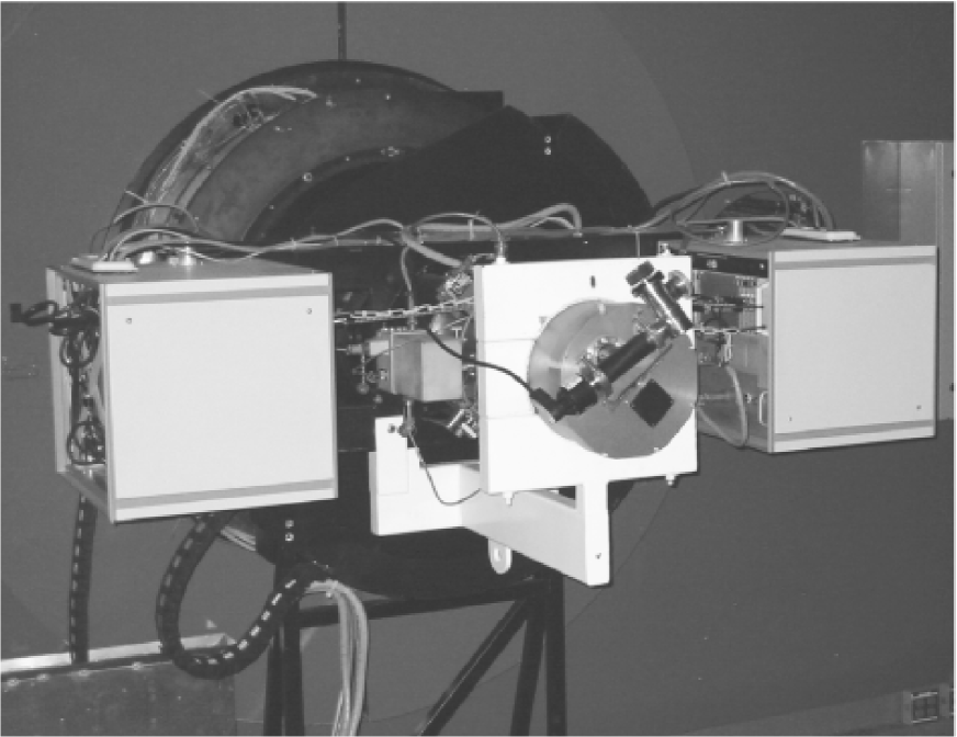
Two small electronics racks are mounted directly to the instrument rotator on either side of PANIC (see Figure 3). These racks include low-noise power supplies, the waveform generator, the ADC unit, a Telebyte 273 Fiber Optics Mux for the clocking signals, a Cold Cathode Model 943 pressure gauge from MKS Instruments, and temperature sensors for these racks. The data acquisition computer was custom built from readily available components, including a 1.6GHz Athlon processor, and runs Windows 98 SE. It is located in an external instrumentation rack, which is currently located on the Nasmyth platform near the instrument. A cable carrier from Igus Inc. is used to support the cables that run between the rotating and nonrotating components. The data acquisition computer commands the waveform generator to generate the clocking signals for array control. These commands are sent via the Fiber Optics Mux. The external rack also contains the two LakeShore units described in the previous section, the filter wheel motor controllers, the ADC power supply, rack temperature sensors, and an Equinox Ethernet Serial Provider, which transfers signals from the instrument control computer to the filter wheel motor controller and from the LakeShore units to the control computer. The low-noise amplifiers described previously are mounted directly to the dewar, as are the filter wheel motors and encoders.
The external rack is connected via Gigabit Ethernet to the instrument control computer, which has a 1.6GHz Athlon processor and runs the Windows 2000 operating system, and a data analysis computer, which has a 2.4GHz Athlon processor and runs the RedHat Linux operating system. The instrument control computer has a series of GUIs that include a range of preset observation macros and readouts for the LakeShore temperature units, in addition to standard control of exposure sequences and the filter wheels. The data analysis workstation includes an array of five 18Gb Seagate 15,000 rpm SCSI drives for rapid data handling and standard astronomical data analysis software. Images are written to the data analysis workstation using network folders and the Samba server software. Both of these computers are currently accessed over the local network by observers using a dual-monitor workstation in the telescope control room. The instrument control computer is accessed remotely with the VNC Viewer software by RealVNC, while the data analysis computer is accessed via a standard secure shell connection.
To supplement the standard data analysis tools in IRAF, we have developed a specialized IRAF package. This panic package contains a set of tools that are resident on the data analysis workstation and can easily be downloaded and installed on an observer’s personal workstation for further analysis after leaving the Observatory. The package includes a number of quick-look tools to difference images and perform quick sky subtraction as data are obtained, as well as a more complete data processing pipeline. In particular, these scripts take advantage of the excellent repeatability of the telescope motions to compensate for telescope offsets and allow accurate registration of the images so that single or multiple dither sequences can be combined automatically and without degradation of image quality. The panic package is available from the instrument web site111http://www.ociw.edu/lco/magellan/instruments/PANIC/panic/index.html, which also contains complete documentation for observers.
6 Commissioning and Performance

|
PANIC was successfully commissioned on the Magellan II (Clay) telescope in April 2003 and immediately went into regular operation. Aside from standard instrument checkout and calibration frames, the main task for the commissioning run was accurate alignment of the instrument pupil. Because PANIC has a fixed pupil mask, the pupil alignment was performed by tip-tilting the instrument on the rotator mount. This was accomplished by identifying a minimum in the sky background through the filter while pointing at a region of relatively blank sky.
The standard mode of detector readout is through the common technique of double-correlated sampling. The detector gain, readnoise, and linearity were measured and found to be well within expected values. The gain is approximately DN-1 and the readnoise has been reduced to nearly after some additional grounding was performed at the telescope. The detector remains linear to better than 1% below at typical background rates (appropriate to the sky background flux through the filter on a warm night), deteriorating to 5% nonlinear at . Saturation occurs at approximately counts. The detector nonlinearity is quite repeatable and corrected as part of the standard data processing pipeline described above. The dark current was measured and found to be less than s-1. Dark frames are not typically obtained, although they are sometimes used for cosmetic purposes when the sky counts do not dominate the noise statistics, or for twilight flats.
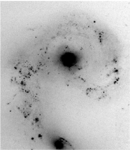
During the commissioning period images as good as FWHM were observed at . The optical design is thus performing extremely well, even producing marginally undersampled data under the best conditions. More typical observed image quality is FWHM. As an illustration of the image quality, a 12 minute exposure of the Antennae Galaxy is shown in Figure 4. Stellar sources are FWHM.
The standard mode of observations in the NIR is to obtain observations at many, slightly offset positions on the sky in order to obtain an accurate and precise measurement of the sky background. To maximize observation efficiency, a series of observation macros were incorporated into the data acquisition software that automatically make small offsets of the telescope and guide cameras. These observation macros include a number of five- and nine-position dither sequences and the size of the offset between each sky position can be tuned to account for the image quality or obtain a large area. The most efficient strategy is to maximize the time between readouts and between telescope offsets. For such cases the on-sky efficiency has been measured to approach 90%.
PANIC moved to the East Nasmyth port of the 6.5m Magellan I (Walter Baade) telescope in July 2003 and is expected to move to one of the folded ports of the Baade telescope within the next year. During its first year of operation, PANIC has proved to be one of the most reliable instruments at the Magellan Observatory. It is currently in use on most bright nights and routinely produces some of the best image quality, as is expected in the NIR.
Acknowledgements.
It is a pleasure to thank the machinists, technicians, and programmers who have contributed to PANIC: Estuardo Vasquez, Darrell Gilliam, Ken Clardy, Robert Storts, and Vincent Kowal. We also thank the excellent staff at Las Campanas Observatory in Chile, and particularly Miguel Roth and Oscar Duhalde for their assistance during commissioning. We also greatly appreciate the financial support provided by the Carnegie Observatories. PM acknowledges support from a Carnegie Starr Fellowship.References
- [1] S. E. Persson, D. C. Murphy, S. M. Gunnels, C. Birk, A. Bagish, and E. Koch, “The Las Campanas Infrared Survey Camera,” AJ 124, pp. 619–634, July 2002.
- [2] W. J. Tropf, “Temperature-dependent refractive index models for BaF2, CaF2, MgF2, SrF2, LiF, NaF, KCl, ZnS, and ZnSe,” Optical Engineering 34, pp. 1369–1373, May 1995.
- [3] D. C. Murphy, S. E. Persson, M. A. Pahre, A. Sivaramakrishnan, and S. G. Djorgovski, “An Infrared Camera for the Palomar Observatory 60-inch Telescope,” PASP 107, pp. 1234–1242, Dec. 1995.