Pixelized Gas Micro-Well Detectors for Advanced Gamma-Ray Telescopes
Abstract
We describe possible applications of pixelized micro-well detectors (PMWDs) as three-dimensional charged particle trackers in advanced gamma-ray telescope concepts. A micro-well detector consists of an array of individual micro-patterned gas proportional counters opposite a planar drift electrode. When combined with pixelized thin film transistor (TFT) array readouts, large gas volumes may be imaged with very good spatial and energy resolution at reasonable cost. The third dimension is determined by timing the drift of the ionization electrons. The primary advantage of this technique is the very low scattering that the charged particles experience in a gas tracking volume, and the very accurate determination of the initial particle momenta that is thus achieved. We consider two applications of PMWDs to gamma-ray astronomy: 1) A tracker for an Advanced Compton Telescope (ACT) in which the recoil electron from the initial Compton scatter may be accurately tracked, greatly reducing the telescope’s point spread function and increasing its polarization sensitivity; and 2) an Advanced Pair Telescope (APT) whose angular resolution is limited primarily by the nuclear recoil and which achieves useful polarization sensitivity near 100 MeV. We have performed Geant4 simulations of both these concepts to estimate their angular resolution and sensitivity for reasonable mission designs.
keywords:
gamma-ray astronomy; Compton telescopes; pair telescopes; gas detectors; Geant4 simulations1 Introduction
The next generation of medium-energy (0.5 – 50 MeV) and high-energy (30 MeV – 100 GeV) gamma-ray telescopes (Compton scatter and pair production telescopes, respectively) will require a substantial improvement in angular resolution in order to greatly improve on the sensitivity of previous and currently-planned missions. In both cases, accurate imaging, which decreases the relative influence of background, relies on a good knowledge of the momenta of secondary particles produced in the primary gamma-ray interaction. These secondary particles are the scattered gamma-ray and recoil electron in the case of Compton scattering, and the electron-positron pairs in the case of pair production. Precisely recording these momenta also enables various background-rejection techniques and greatly increases the sensitivity of the telescope to the polarization of the incident radiation.
The initial secondary particle momenta are masked by poor spatial resolution and by multiple Coulomb scattering of charged particles within the detector materials. These factors have contributed to an enlarged point spread function (PSF) in current gamma-ray instruments and, in the case of pair production telescopes, have totally suppressed the polarization sensitivity. Improving this picture will require a low-density tracking medium with high spatial readout resolution. We therefore propose basing future gamma-ray instruments on micro-pattern gas detectors. Here we outline possible designs for Compton and pair telescopes using pixelized gas micro-well detectors under development at NASA/GSFC.
2 Pixelized Micro-Well Detectors
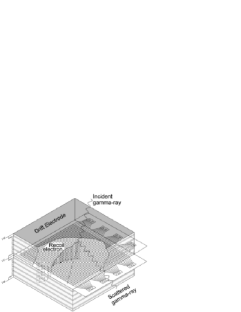
The micro-well detector (MWD) is a type of gas proportional counter based on micro-patterned electrodes (Deines-Jones et al., 2002a, b). Each sensing element consists of a charge-amplifying well (Fig. 1).

The cathode and anode electrodes are deposited on opposite sides of an insulating substrate. The well is formed as a cylindrical hole through the cathode and substrate, exposing the anode. An array of such wells forms a detector, with the active tracking volume bounded by a drift electrode. Ionization electrons produced by the passage of a fast charged particle drift toward the anodes and into the wells. An ionization avalanche occurs in each well, where an intense electric field is set up by the voltage applied between the anode and cathode. Micro-well technology is very robust, and allows large areas to be read out with good spatial ( m) and energy (18% FWHM at 6 keV) resolution at low cost.
We are working with our collaborators Thomas Jackson, Bo Bai, and Soyoun Jung at Penn State University to develop pixelized micro-well detectors (PMWDs) to enable true imaging of charged particle tracks. In this approach, each anode pad is connected to an element of a thin-film transistor (TFT) array. The individual transistor gates are connected in columns, and the outputs are connected in rows. The gate drivers for each column are then activated sequentially, allowing the charge collected on the anode pads to be read out by charge-integrating amplifiers at the end of each row. Thus a two-dimensional projected image of the charged particle track is recorded. The third dimension may be determined by measuring the drift time of the ionization electrons using the signals from the cathodes. Ideally, the MWD and TFT array would be fabricated together as a single unit on a robust, flexible substrate such as polyamide (e.g., KaptonTM).
3 Advanced Particle Tracker
These combined PMWD-TFT arrays will be assembled into modular detector units called three-dimensional track imaging detectors (TTIDs), as shown in Fig. 2.
Each TTID comprises two 30 cm cm, back-to-back PMWD-TFT arrays bounded by drift electrodes (5 cm drift distance on each side) and field-shaping electrodes on the four walls. The front end electronics, gate drivers, and timing electronics, together with their high-density interconnects, are distributed around the periphery of the module and then folded up along the walls.
We have developed a concept for a large-volume charged particle tracker based on TTID modules, shown schematically in Fig. 3.

We assume the PMWD-TFT arrays have a pitch of 200 m and that a Xe/CO2 gas mixture (98%/2%) is used. We also assume 10 ns timing resolution, which gives a drift distance resolution of 140 m for the maximum electron drift velocity in this gas mixture. The walls of the TTIDs are made of polyamide 300 m thick. The TTID modules are grouped into 30 cm 30 cm cubes, and arranged such that the drift direction in each cube is rotated 90∘ relative to adjacent cubes; this gives a “stereo” view of extended tracks. A 3 m diameter pressure vessel would allow 61 cubes to be arranged inside per layer, giving 54900 cm2 of geometric area while fitting within the payload fairing of a Delta III or IV launcher.
We have used Geant4.5.1 to simulate the performance of such a particle tracker. Due to known errors in the multiple Coulomb scattering process in later versions of Geant4, we used a slightly modified version of the multiple scattering class from version 3.2. In the following we describe our preliminary results for two possible uses of the charged particle tracker: an advanced Compton telescope and an advanced pair telescope.
4 Advanced Compton Telescope
The Advanced Compton Telescope (ACT) is envisioned as a -fold increase in sensitivity over that of CGRO/COMPTEL, the only Compton telescope that had enough sensitivity to make astronomical observations (Schönfelder et al., 1993). Part of this increase can be achieved by accepting larger Compton scatter angles, increasing the effective area. The rest will have to come from a dramatic decrease in the telescope PSF, which reduces the area of the sky from which a given source’s photons could have originated. This will reduce contamination both from internal background and from nearby sources.
There are two components to the PSF of a Compton telescope (Bloser et al., 2004a). The first is the error in the computed scatter angle . (This is often referred to as the angular resolution measure, or ARM.) This width is determined by the spatial and energy resolution of the detectors that make up the telescope. The second component, , is roughly given by the error in the measurement of the recoil electron’s initial direction, projected onto the plane perpendicular to the scattered photon direction. COMPTEL was not able to track the recoil electron at all, and so . The PSF for a single photon was thus an annulus on the sky (the “event circle”) with the diameter given by the scatter angle and the width by . The total angular area of the PSF, , was therefore quite large for all but the smallest scatter angles. The ACT must accept scatter angles up to or greater, and so good electron tracking may well be critical to keep the PSF, and therefore background, within reasonable limits. This is particularly true for good polarization sensitivity, since the maximum polarization signal will be recorded for events with (Bloser et al., 2004a).
We have performed Geant4 simulations of an ACT concept using the gas particle tracker described in Sec. 3 with a depth of 2.7 m, filled with Xe/CO2 gas with a pressure of 3 atm. The tracker is surrounded by a calorimeter made up of CsI pixels to absorb the scattered photon. We assumed CsI pixel dimensions of 5 mm 5 mm, with a depth of 5 cm on the sides of the tracker and 10 cm on the bottom. We optimistically assumed an energy resolution in the CsI of 5% (FWHM) at 662 keV, which is one of the main contributors to . In addition, we used the G4LECS package (Kippen, 2004) to calculate the Doppler broadening, a slight increase in due to scattering off bound electrons with unknown momenta in their atomic shells. We simulated 2 MeV photons entering the telescope on-axis, and applied a simple detector response (diffusion of drift electrons in the gas, energy resolution, and binning into pixels) and event reconstruction to the output of the simulation.
Our results revealed a flaw in this ACT tracker design, which will be corrected in the next iteration: the recoil electrons lose energy in the polyamide walls of the TTID modules, leading to large errors in the measured electron energy. This can be seen in Fig. 4, which shows the total energy spectrum recorded by the telescope for two cases: 300 m thick polyamide TTID walls (dotted curve), and TTID walls artificially set to vacuum (solid curve).

Such large energy loses in the tracker due to the TTID walls lead both to incorrect energy measurements and to incorrect image reconstruction. In future simulations, the TTID modules will be made larger (50 cm on a side or more), and each will be surrounded by its own mini-calorimeter, so that electrons leaving the tracking volume will immediately have the remainder of their energy measured. For the present scheme, the total energy resolution at 2 MeV is about 5% FWHM.
To demonstrate the imaging capability of our ACT concept, we present in Fig. 5 the image derived at 2 MeV by simple back projection of individual events (without polyamide walls).

A fit with a 2-dimensional Gaussian gives a width of . The ability to preform “true” imaging by back projection in this manner is a great simplification over COMPTEL and other instruments with poor electron tracking, which require complicated reconstruction methods to produce an image from overlapping event circles. The effective area of this ACT concept at 2 MeV is cm2. Calculation of the sensitivity will require a realistic estimate of the in-flight background.
5 Advanced Pair Telescope
The angular resolution of a pair production telescope is limited by the multiple scattering of the electron and positron in the detector material and by the unknown recoil of the particle (nucleus or electron) in whose field the pair conversion took place. Hunter et al. (2001) have shown that a pair telescope can nearly achieve recoil-limited resolution, approaching 1 arcmin above a few GeV, if the density of the tracking medium can be made less than radiation lengths (RL) per track measurement interval. Bloser et al. (2004b) showed that a pair telescope that achieved this density should in principle also be moderately sensitive to polarization at MeV, since the azimuthal plane of the pair is weakly correlated with the polarization vector.
We have simulated a concept for an Advanced Pair Telescope (APT) using the particle tracker of Sec. 3. The desired density of RL per measurement is met with our 200 m pitch if we use a Xe/CO2 gas mixture at a pressure of 1.5 atm. A depth of 5.1 m then provides RL of total interaction depth for pair conversion, similar to previous instruments. The telescope does not include a massive calorimeter; rather, the energy of the pair particles may be estimated by their average degree of scattering. (For this reason the small amount of energy lost by electrons with several tens of MeV in the polyamide walls is of no concern for our APT concept.) The same detector response is applied as for the ACT simulations, and the incident photon direction is found by adding the momenta of the electron and positron. We made use of a pair conversion class for Geant4 that includes the effects of polarization on the cross section (Bloser et al., 2004b) to estimate the polarization sensitivity at 100 MeV.
The derived angular resolution, defined as the angular radius containing 68% of the total events, is shown in Fig. 6.

The resolution is nearly an order of magnitude worse than that predicted by Hunter et al. (2001). This is due to the diffusion of ionization electrons as they drift to the wells; for our Xe/CO2 gas mixture the initial ionization cloud has spread by mm after drifting for 5 cm (Peisert & Sauli, 1984). This blurs the particle tracks and makes them hard to measure precisely, especially near the pair vertex where the tracks are close together. The current APT design does not have a useful polarization sensitivity for the same reason. We are currently investigating means of reducing the diffusion in order to achieve the desired angular resolution and polarization sensitivity. The most promising method appears to be the addition of an electronegative gas (e.g. CS2) which causes the ionization electrons to attach themselves to the ions, which then drift with much smaller diffusion (Martoff et al., 2000).
Acknowledgments
We thank G. Depaola and F. Longo for the Geant4 pair polarization class and T. Burnett for the modified Geant4.3.2 multiple scattering class. This work was performed while the author held a National Research Council Research Associateship Award at NASA/GSFC.
References
- Bloser et al. (2004a) Bloser, P., et al. 2004a, New Astron. Rev., 48, 299
- Bloser et al. (2004b) Bloser, P., Hunter, S., Depaola, G., & Longo, F. 2004b, Proc SPIE, 5165, 322
- Deines-Jones et al. (2002a) Deines-Jones, P. et al. 2002a, NIM-A, 477, 55
- Deines-Jones et al. (2002b) Deines-Jones, P. et al. 2002b, NIM-A, 478, 130
- Hunter et al. (2001) Hunter, S., Bertsch, D., & Deines-Jones P. 2001, in AIP Conf. Proc. 587, Gamma 2001, ed. S. Ritz, N. Gehrels, & C. Shrader (New York: AIP), 848
- Kippen (2004) Kippen, R. M. 2004, New Astron. Rev., 48, 221
- Martoff et al. (2000) Martoff, C. J., et al. 2000, NIM-A, 440, 355
- Peisert & Sauli (1984) Peisert, A., & Sauli, F. 1984, CERN tech. rep. 84-08
- Schönfelder et al. (1993) Schönfelder, V., et al. 1993, ApJS, 86, 657