Further author information: Send correspondence to G. Skinner
E-mail: skinner@cesr.fr,
Telephone: 0033 5 61 55 85 61
Fresnel lenses for X-ray and Gamma-ray Astronomy
Abstract
Phase Fresnel lenses have the same imaging properties as zone plates, but with the possibility of concentrating all of the incident power into the primary focus, increasing the maximum theoretical efficiency from 11% to close to 100%. For X-rays, and in particular for gamma-rays, large, diffraction-limited phase Fresnel lenses can be made relatively easily. The focal length is very long - for example up to a million kms. However, the correspondingly high ‘plate-scale’ of the image means that the ultra-high (sub-micro-arc-second) angular resolution possible with a diffraction limited gamma-ray lens a few metres in diameter can be exploited with detectors having mm spatial resolution.
The potential of such systems for ultra-high angular resolution astronomy, and for attaining the sensitivity improvements desperately needed for certain other studies, are reviewed and the advantages and disadvantages vis-à-vis alternative approaches are discussed.
We report on reduced-scale ‘proof-of-principle tests’ which are planned and on mission studies of the implementation of a Fresnel telescope on a space mission with lens and detector on two spacecraft separated by one million km. Such a telescope would be capable of resolving emission from super-massive black holes on the scale of their event horizons and would have the sensitivity necessary to detect gamma-ray lines from distant supernovae.
We show how diffractive/refractive optics leads to a continuum of possible system designs between filled aperture lenses and wideband interferometric arrays.
keywords:
X-ray astronomy, Gamma-ray astronomy, Lenses, Fresnel, Interferometry1 INTRODUCTION
If one can obtain a strong enough signal and if at the same time diffraction-limited performance can be achieved, then the high-energy X-ray or gamma-ray parts of the spectrum are the natural wavebands in which to seek ultra-high angular resolution (Table 1).
It is remarkable that the same technique seems to be capable of turning both of these ‘ifs’ into reality. It is even more remarkable that the optical system needed does not require any high technology but could be constructed today. The technique which seems to offer this remarkable combination is that of Phase Fresnel lenses, a variation on Fresnel zone plates.
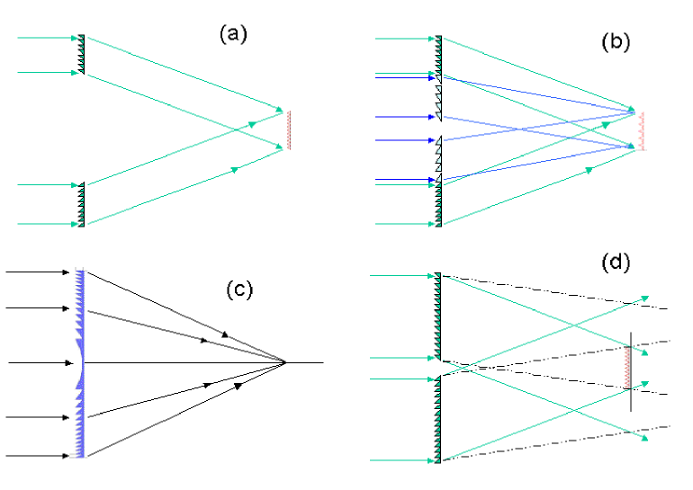
Fresnel Zone Plates (FZPs, Figure 1a), as invented by Soret[1] , focus radiation by blocking it! More precisely they block with opaque annuli the Fresnel zones from which the radiation which would arrive at the desired focus with the wrong phase. Not surprisingly, they are not very efficient. In addition to the 50% of incident radiation which is absorbed, 25% passes undiverted and nearly 15% goes not into the primary focus ( for a converging lens) but into secondary focii corresponding to . The maximum theoretical efficiency is , or about 10%.
| Band | Energy | Wavelength | Diameter |
|---|---|---|---|
| Radio | 5 mm | 2.5 km | |
| Optical | 2.5 eV | 500 nm | 250 km |
| X-ray | 6 keV | 0.2 nm | 105 m |
| Hard X-ray | 100 keV | 12 pm | 6.25 m |
| Gamma-ray | 1 MeV | 1.2 pm | 62.5 cm |
Although 10% is not bad compared with some other techniques, one can do better. As well as independently proposing the FZP, Rayleigh pointed out the possibility (first demonstrated by Wood[2]) of circumventing the absorption and ‘straight-through’ () losses in what can be termed the Phase Zone Plate (PZP, Figure 1b).
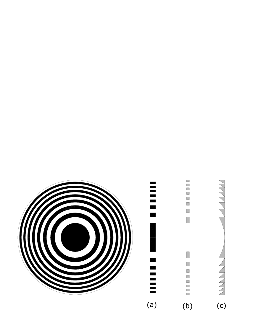
The opaque regions are replaced by ones that allow the radiation to pass, but which have a thickness of refractive material such as to impose a phase shift of . The theoretical efficiency limit is raised to 40.4%.
Even better, the refractive material can be profiled to give at each radius in the lens the phase shift such that radiation arrives at the focal point with exactly the correct phase, not just the nearest multiple of . This leads to what we term here a ‘Phase Fresnel Lens’ (PFL, Figure 1c)). This phrase is adopted here to distinguish such lenses from those originally invented by Fresnel for use in lighthouses, which are best considered as simple assemblies of prisms combining light beams incoherently. Confusingly these incoherent ‘Fresnel lenses’ are distinct from the lenses of which we speak here which rely on modifying the phase of ‘Fresnel Zones’.
The use of PFLs for X-rays and gamma-rays is possible because all materials have a refractive index which differs from unity, if only by a tiny amount. For X-rays and gamma-rays the refractive index is , where is small and positive, corresponding to a refractive index slightly less than one (it seems to have been Einstein who first pointed this out in 1918[3]).
The efficiency of a PFL is limited only by any inaccuracies in the profile, by absorption or incoherent scattering in the lens material and by reflective losses at the interfaces. It is easy to show that if the deviations from the ideal profile correspond to or less, then the resulting losses will not be greater than 9.9%. As an example of absorption in the lens, consider a PFL made of aluminium working in the first order at 500 keV. The mean lens thickness will be 0.57 mm, and the losses in the material only 1.3%. For energies and materials for which Compton scattering dominates, the losses are independent of material and increase in proportion to photon energy. For low materials, they are important only below a few keV or above 5–10 MeV. Because the refractive index are always so close to unity, reflective losses at interfaces are always negligible.
We will discuss here the application of Phase Fresnel Lenses to astronomy and also consider how certain variations on this technique allow a continuum of possibilities between a simple lens and an interferometric array.
2 ASTRONOMICAL APPLICATIONS
The astronomical use of X-ray and gamma-ray PFLs has been discussed by Skinner [4, 5, 6] (see also the suggestions of Gorenstein [7] for X-ray applications).
The possible applications fall into two classes. In the first the main interest is in the superb angular resolution possible with this technique. The second class of applications uses PFLs to overcome the present impasse in gamma-ray astronomy in which scaling up of existing technologies to improve their sensitivity is impracticable and maybe even be counterproductive (because larger systems require larger shields that both lead to worse dead-time losses and create more neutrons and other secondary particles).
2.1 Angular Resolution
Among the astronomical objectives which could be achieved using the superb angular resolution possible with a high energy PFL are:
-
1.
Studies of the environment of super-massive black holes in the nucleii of active galaxies, on the scale of the event horizon.
-
2.
Investigation of the ejection mechanism in galactic micro quasars.
-
3.
Imaging of active regions on the surfaces of (relatively) nearby stars and of the interacting wind systems in close binaries.
-
4.
Visualisation of the explosion of supernovae and of the escape of their radioactive by-products.
2.2 Sensitivity
Very high sensitivity is important for the above applications but the possibility of having tens of square metres of effective area focussed onto a small, low background, detector opens up new possibilities even in cases where the objects are not resolvable.
Thus although the radioactive ejecta of a Type Ia supernova could be imaged“only” for those closer than about 50 Mpc ( 1 per year), the sensitivity of a PFL telescope would make possible the observation and spectral study of many more supernovae. For example gamma-ray emission should be detectable from Type Ia supernovae out to z=0.1 and the narrower, but much weaker, lines expected from SN II should be observable to 70 Mpc.
3 CHALLENGES
3.1 Bandwidth
Because of the low aperture of practical X-ray and gamma-ray PFLs, most aberrations are negligible. However, PFLs are inherently chromatic, with a focal length which is proportional to photon energy. The bandwidth beyond which chromatic aberration will start to degrade the diffraction limited performance is given by
| (1) |
Achromatic combinations of diffractive and refractive lenses have been suggested[6, 7, 8] but the useful bandpass is still limited.
For narrow line radiation this is not too much of a disadvantage as the lens may be designed for the relevant energy. Although ideally the lens thickness should correspond exactly to the for a given energy, in practice a lens designed for an energy can be used over a band (say) 0.7 to 1.5. Thus multiple lines and the regions around and between them can be explored with the same lens by adjusting the focal length.
For continuum sources, because of the way the flux is concentrated onto a small, low background, detector, one tends to find that the sensitivity is surprisingly good, despite the fact that only a small fraction of the incident radiation is used.
Of course radiation at energies either side of the that for which the system is configured will also arrive at the detector. It will be less well focussed. For the best angular resolution an energy resolving detector must be used to ignore such radiation. For spectral and other studies, though, it can still carry important information.
Note that whether or not an achromatic combination is used, the bandpass increases in direct proportion to .
3.2 Orbital considerations
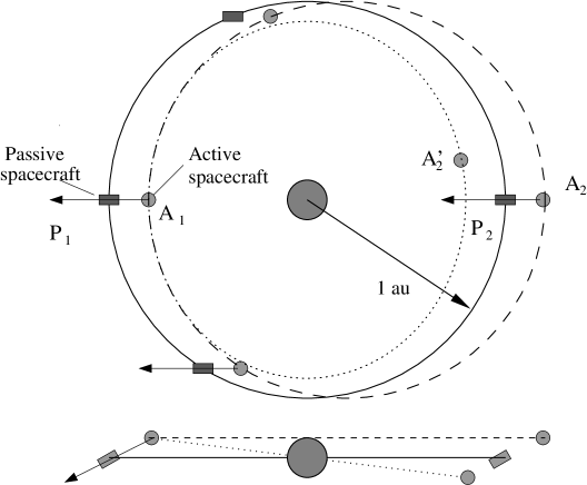
For a two satellite system with constant orientation in inertial space, one of the satellites is necessarily in non-Keplerian orbit and its position has to be maintained by a constant thrust[5]. Minimising the gravity gradient forces dictates an orbit well away from the earth-moon system. Studies[9] have shown the feasibility of a ‘drift-away’ orbit trailing the earth at 1 a.u. from the sun. The station-keeping forces needed are well within the capabilities of ion thrusters already available. Alternatively a situation close to a Lagrangian point could be considered.
The forces necessary to accelerate and decelerate one of the spacecraft to change the telescope pointing are also an important consideration. With careful mission planning and allowing a few weeks for a major repointing, they are comparable with the station-keeping forces. This is not surprising if one considers that simply shutting off the station-keeping thrusters would lead to vector joining the two spacecraft reversing on a time-scale of 6 months (Figure 2).
|
3.3 Pointing knowledge
Perhaps the most crucial consideration is the issue of determination of the pointing direction (as defined, for example, by the line joining the centre of the lens to the centre of the detector). The problem the same for any for any ultra-high resolution telescope – one has to know where the target is and where the telescope is pointing, and one has to know it with an accuracy better than the field of view and with a stability better than the required resolution.
4 LONGER IS BETTER?
The focal length of a PFL (or equally a FZP or PZP) can be expressed as
| (2) |
where is the operating energy, is the pitch of the pattern near the periphery and is the diameter of the lens. Here we allow for the fact that higher orders of diffraction, can in principle be used.
The diffraction-limited angular resolution is
| (3) |
A natural and frequently asked question is whether there is not some way of reducing the focal length of a Fresnel telescope system. Reductions from the extreme values of 106 km, which is suggested by the values used for normalising the parameters in Equation 2, are certainly possible. With some sacrifice in angular resolution either or can be decreased. More importantly, reducing will reduce the focal length in proportion.
The only limits on reducing are practical ones. The thickness of the lens, , will be fixed by the working energy and by the material chosen : where
| (4) |
The approximate form given here for in terms of density is only valid well above any absorption edges. It assumes a number of electrons per nucleon of 0.48, as for Al, but this ratio is in the range 0.38–0.5 for all elements Z4. Reducing leads to structures with higher and higher aspect ratio .
The focal length can also be reduced by using , but for a PFL this means that the thickness will be increased and again the aspect ratio will be correspondingly higher.
Accepting that shorter focal lengths are possible, are they desirable? From a spacecraft point of view – yes. The thrust necessary to overcome gravity gradient forces and maintain a non-Keplerian orbit is usually proportional to the separation (it can increase even faster if the system has been positioned near a Langrangian point to minimise gravity gradient effects). Also the fuel and/or time needed to reorient the telescope by manoeuvering one satellite around the other will be higher for large separations.
The field of view for a given detector size will of course also be improved for a relatively short focal length.
On the other hand from the point of view of the performance of the telescope, there is a lot to be said for long focal lengths :-
-
•
Chromatic abberation: As discussed in section 3.1, the bandpass is proportional to .
-
•
Plate scale: Particularly at high energies, the spatial resolution of detectors is limited. Even when a gamma-ray photon is stopped in a single photo-electric interaction, the resulting energy deposit is spread over the path length of the electron in the detector material. For a simple PFL (or FZP/PZP) the spatial focal spot size corresponding to diffraction limited angular resolution is or . Thus little is gained by reducing beyond a few times the detector resolution.
-
•
Navigation: A possible solution to the problem of pointing determination is to measure the positions of the two satellites and so deduce the direction of the vector joining them. Spacecraft positions are routinely determined to a few meters. Unless one has a detector some 10 m or more in size, this by itself is not sufficient to bring a specific object within the field of view. But by using techniques similar to those of the GPS, there is a real prospect of improving the knowledge of the relative position of the two to the centimeter or millimeter scale. With a focal length of km, 0.5 cm precision would lead to a determination of telescope orientation at the 1 level. If the focal length is reduced too much this approach is no longer viable.
5 GROUND TESTING
One problem with any space-based optical system, focussing or interferometric, which has components separated by km or more, let alone by a million km, is ‘how can it be tested?’. In fact there are two related problems - proof of concept and testing of prototype/engineering-model/flight hardware.
It might be argued that testing of the X-ray/gamma-ray performance of a phase Fresnel lens system is unnecessary – that metrology, together with a knowledge of the index of refraction of the material(s) used would be sufficient. The metrology is not especially demanding - for a typical long focal length gamma-ray Fresnel lens the profiling has a finest scale of the order of millimeters and so the optical precision considered above corresponds to 50 m. The index of refraction can be directly calculated from scattering factors. Detailed computation of these factors are available [12] and have been verified against measurements in certain cases [13]. The combinations of interest will, furthermore, be among those for which the calculations are most accurate – scattering in the forward direction by light atoms, well above absorption edges.
However, we take the view that it would be unwise to invest in a major space mission without ‘proof of concept’ measurements and we have been pursuing two general paths for demonstrating the principles involved.
5.1 Testing miniaturised lenses
The first approach is to test a scaled down system. Equation 2 shows how the scaling dependends on the system parameters and Table 2 gives some example values which correspond to testing with the focal length reduced by a factor of 2 million. Even this is not enough to bring the total source/detector distance within the range of vacuum test facilities, so we propose stacking (say) four lenses in series to increase their power. Although the angular resolution will not be as good as the sub-micro arc-second performance of the final system it should nevertheless be about 1 milli arc-second.
| Effect on | Example value | Factor | |||
| focal length | Flight | Ground | |||
| Energy | 500 keV | 60 keV | 8.3 | ||
| Lens diameter | 5 m | 5 mm | 1000 | ||
| Finest pitch | 1.0 mm | 4 m | 250 | ||
| Total scaling | |||||
| Focal length | km | 500 m | |||
| Diffraction limit | 0.12 micro arcsec | 1 milli arcsec | |||
| Lenses in series | 1 | 4 | |||
| Source-lens distance | 250 m | ||||
| Lens-detector distance | km | 250 m | |||
5.2 Interferometric testing of gamma-ray lenses
The most promising way of testing a more representative lens seems to be by using interferometric techniques.
The action required of a lens is to change the radius of curvature of the incoming radiation. In the case of focussing a parallel beam it is changed from infinity to a curvature (positive by convention) corresponding to converging radiation. Strongly diverging radiation () falling on the same lens will become slightly less diverging.
 |
We propose to detect this change in radius by gamma-ray interferometry. To create an interference pattern, the outgoing radiation must be combined with a sample of the incoming radiation. This can be done if narrow slits are made in the lens (Figure 3). Sufficiently far beyond the lens, the diffractive spread will be such that the radiation passing through the slits and that passing through the lens will have become mixed. For slits of width , typical separation , this will happen for distances greater than about . Where the lens has the thickness , the lens will be like a transparent window, where , the transmitted flux will go to zero. Of course, the photons and their energy do not simply disappear, they are diverted into orders of the phase modulating aperture formed by the slits. If the slits are periodic with , they simply form a diffraction grating and the energy will go mainly into orders , diverted by angles .

|
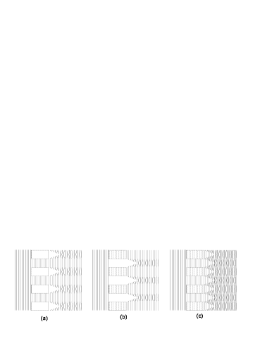
For this effect to be detectable, one has to observe the pattern far enough away that the beams are well separated, that is to say they have been deflected from the straight-through, , direction by more than their width i.e., , where there are slits. Table 3 shows that with possible parameters the deflection can be nearly 10 times . Simulations of the fringe patterns expected are shown in Figure 5.
Making 0.5 micron wide slits in material several hundred microns thick would be difficult, so we are proposing to make parts of the lens from alternating high density/low density materials, with the low density material taking the place of the slits.
Ideally the test would be done with a vacuum beamline, but we are considering the possibility of using a flexible tube filled with Helium or even accepting the high absorption and scattering losses associated with a test in open air. Table 4 illustrates some possibilities.
| Parameter | Example value | ||
|---|---|---|---|
| Energy | 500 | keV | |
| Wavelength | m | ||
| Slit width | 0.5 | m | |
| Slit period | 1.0 | m | |
| Number of slits | 40 | ||
| Observing distance | 500 | m | |
| Source distance | 500 | m | |
| Assumed source size | 100 | m | |
| Minimum distance for mixing | 0.20 | m | |
| Displacement of beam by diffraction | 1.24 | mm | |
| Spread due to finite source size | 0.10 | m | |
| Spread due to diffraction | 0.03 | mm | |
| Spread due to width of beam (slits) | 0.08 | mm | |
| Total spread | 0.13 | mm | |
| FOM = Displacement/Spread | 9.4 | ||
| Energy | Source | Distance | Medium | Transmission |
|---|---|---|---|---|
| (keV) | (m) | (%) | ||
| 100 | X-ray generator | 500 | Vacuum | 100 |
| 500 | Betatron | 1000 | He | 21 |
| 1000 | Betatron | 500 | Air | 2.2 |
6 A CONTINUUM OF POSSIBILITIES
The most studied approach to getting ultra high angular resolution in high energy astronomy is through X-ray interferometry. The ideas presented here represent an alternative but the two lines of approach are not entirely distinct. With multiple mirror assemblies concentrating flux onto a single detector assembly, where they all constructively interfere at a single point, the MAXIM concept is not very different from a focussing optical system with an unfilled aperture. Likewise, a PFL could provide a useful performance with only part of the aperture effective.
Skinner[6] has suggested that a diffractive/refractive component could be used in a beam combiner in an interferometer for X-rays or gamma-rays (Figure 6a). In fact, the region over which flux is collected could be increased by adding more area as in Figure 6b with a different pitch to direct the same wavelength towards the detector. A natural extension would be to have not just two periods, but a graded pitch – and one arrives again at a PFL (Figure 6c).
Alternatively, the pitch could be kept constant, as in a diffraction grating (Figure 6d). This last arrangement is particularly interesting. Of the radiation arriving with a particular off axis radius , there will always be one wavelength for which the deflection angle leads to an interference pattern in the detector plane. The interference pattern formed is independent of wavelength – for two diffractors, it will just a set of parallel fringes of the form , where is the distance from the axis of a point in the detector plane. The pitch is simply equal to one half , independent of wavelength. If the system has axial symmetry, the radial dependence of the wave amplitude will be a zero order Bessel function, , and so the power will be . Again the scale is independent of photon energy. Basically what is happening is that longer wavelengths are diffracted from parts of the diffractor at larger radii, and so the wavefronts arrive at the detector with a larger angle between the two interfering wavefronts. The resulting interference pattern always has the same scale
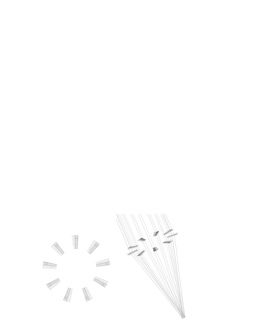
It is easy to imagine a system in which a number of such diffractors are used in a configuration similar to that of the MAXIM baseline (Figure 7). Assuming that the diffractors are much larger than the detector plane, the range in energy will be approximately . So for a 10% bandpass, they need to be in length, where will be dictated by the aperture size corresponding to the required resolution and the longest wavelength. If necessary, the bandpass can be improved by placing diffractors for adjacent bands alongside the original ones. With a sufficiently large number of diffractors, the response will approximate the one for a complete annulus.
Although the optical elements would be large, they would be relatively easy to manufacture, tolerances and alignment requirements would be very easily achieved, and there would be no loss in efficiency associated with reflections at multiple surfaces.
Between a filled aperture system with pattern pitch following the rule for a zone plate scheme as in Figure 1 and a sparse array with constant pitch diffractors (Figure 7), a continuum of possibilities can be imagined. Further studies are certainly needed to identify the most interesting combinations.
References
- [1] J. L. Soret, “Ueber die durch Kreisgitter erzeugten Diffractionsphänomene,” Annalen der Physik und Chemie 156, pp. 99–113, 1875.
- [2] R. W. Wood, “Phase reversal zone-plates and diffraction-telescopes,” Phil. Mag. 45, pp. 511–523, 1898.
- [3] A. Einstein, “Lassen sich Brechungsexponenten der Körper für Röntgenstrahlen experimentell ermitteln,” Verh. Dtsch. Phys. Ges. 20, pp. 86–87, 1918.
- [4] G. K. Skinner, “Prospects for high angular resultion in gamma-ray astronomy,” PASP Proc. IAU 205, 2001.
- [5] G. K. Skinner, “Diffractive/refractive optics for high energy astronomy. I. Gamma-ray phase Fresnel lenses,” Astron. Astrophys. 375, pp. 691–700, Aug. 2001.
- [6] G. K. Skinner, “Diffractive-refractive optics for high energy astronomy. II. Variations on the theme,” Astron. Astrophys. 383, pp. 352–359, Jan. 2002.
- [7] P. Gorenstein, “Concepts: X-ray telescopes with high-angular resolution and high throughput,” in X-Ray and Gamma-Ray Telescopes and Instruments for Astronomy. Edited by Joachim E. Truemper, Harvey D. Tananbaum. Proceedings of the SPIE, Volume 4851, pp. 599-606 (2003)., pp. 599–606, Mar. 2003.
- [8] Y. Wang, W. Yun, and C. Jacobsen, “Achromatic Fresnel optics for wideband extreme-ultraviolet and X-ray imaging,” Nature 424, pp. 50–53, 2003.
- [9] Integrated Mission Design Center, “Mission study : Fresnel lens gamma-ray telescope,” tech. rep., NASA GSFC, Greenbelt, Md, 2002.
- [10] K. C. Gendreau, J. Leitner, L. Markley, W. C. Cash, and A. F. Shipley, “Requirements and options for a stable inertial reference frame for a 100-micro-arcsecond imaging telescope,” in Interferometry in Space. Edited by Shao, Michael. Proceedings of the SPIE, Volume 4852, pp. 685-694 (2003)., pp. 685–694, Feb. 2003.
- [11] Integrated Mission Design Center, “Mission study : Micro-arcsecond x-ray imaging mission pathfinder (maxim-pf),” tech. rep., NASA GSFC, Greenbelt, Md, 2002.
- [12] L. Kissel, B. Zhou, S. C. Roy, S. Sen Gupta, and R. Pratt, “The validity of Form-Factor, Modified Form-Factor and Anomolous-Scattering-Fraction Approximations in Elastic Scattering Calculations,” Acta Cryst. A 51, pp. 271–288, 1995.
- [13] G. Basavaraju, P. P. Kane, L. Kissel, and R. Pratt, “Elastic scattering of 88.03-keV gamma-rays,” Phys. Rev. A 51, pp. 2608–2610, 1995.