Formation of Semi-relativistic Jets from Magnetospheres of Accreting Neutron Stars: Injection of Hot Bubbles into a Magnetic Tower
Abstract
We present the results of 2.5-dimensional resistive magnetohydrodynamic (MHD) simulations of the magnetic interaction between a weakly magnetized neutron star and its accretion disk. General relativistic effects are simulated by using the pseudo-Newtonian potential. We find that well-collimated jets traveling along the rotation axis of the disk are formed by the following mechanism: (1) The magnetic loops connecting the neutron star and the disk are twisted due to the differential rotation between the neutron star and the disk. (2) Twist injection from the disk initiates expansion of the loop. (3) The expanding magnetic loops create a magnetic tower in which accelerated disk material travel as collimated bipolar jets. The propagation speed of the working surface of the jet is the order of 10% of the speed of light (). (4) Magnetic reconnection taking place inside the expanding magnetic loops injects hot bubbles intermittently into the magnetic tower. The ejection speed of the bubble is the order of the local Alfvén speed of the launching point and in our simulations. (5) The hot bubbles moving inside the tower catch up with the working surface of the jet. High energy electrons created by the magnetic reconnection are a plausible source of radio emission. Our model can explain the formation process of a narrow jet from a weakly magnetized ( gauss) neutron star and the correlation between radio flares of the core and of the lobe observed in Sco X-1.
Subject headings:
accretion, accretion disks — relativity — MHD — stars: neutron — ISM: jets and outflows1. INTRODUCTION
The mechanism of jet formation is one of the most important subjects of research in astrophysics. Blandford & Payne (1982) studied magneto-centrifugal acceleration along a magnetic field line threading an accretion disk. Uchida & Shibata (1985) and Shibata & Uchida (1986) showed by time-dependent magnetohydrodynamical (MHD) simulations that bipolar jets are produced from an accretion disk threaded by open magnetic field lines.
Observational evidence indicate the presence of semi-relativistic jets in some galactic X-ray binaries (XRBs) such as SS433 (Hjellming & Johnston 1981), Cygnus X-3 (Martí et al. 2000, Mioduszewski et al. 2001), Sco X-1 (Fomalont et al. 2001a,b), and Circinus X-1 (Fender et al. 1998). The speed of jets in such XRBs indicates that the jets are launched close to the last stable orbit of the accretion disk. Therefore, we should include general relativistic effects around a compact object. In addition, the magnetic field of the compact object may play an essential role in the dynamics of the jets and the accretion flow. Recent observations of XRBs by the Very Large Baseline Interferometer (VLBI) revealed their energetic activities such as radio flares and radio jets. VLBI discovered the motions and variabilities of radio lobes in Sco X-1 (Fomalont et al. 2001a,b). According to their observations, radio lobes are ejected from the core of Sco X-1. After the radio flare of the core, the intensity of the advancing radio lobe increases. The correlation between the core flare and the lobe flare in Sco X-1 indicates that explosive events at the core transports energy to the lobe.
A plausible model of advancing lobes is the working surface of jets ejected from the core. However, the existence of large scale open magnetic fields assumed in the magneto-centrifugal model of jet formation is not evident in XRBs. Instead, we should take into account the magnetic interaction between the neutron star and its accretion disk.
Lynden-Bell & Boily (1994) studied the evolution of force-free magnetic loops anchored to the star and the disk. They obtained self-similar solutions for the evolution of the magnetic loops. They found that the loops are unstable against the twist injection from the rotating disk and that the loops expand along a direction of 60 degrees from the rotation axis of the disk. Lovelace et al. (1995) pointed out that the dipole magnetic field of the star deforms itself into an open magnetic field due to the differential rotation between the star and the disk. Subsequently, Lynden-Bell (1996; hereafter referred to as LB96) showed that a cylindrical magnetic tower is formed when the disk is surrounded by external plasma with finite pressure.
Hayashi, Shibata, and Matsumoto (1996; hereafter referred to as HSM96) carried out the first numerical calculations of magnetic interaction between a protostar and its accretion disk. By assuming Newtonian gravity and neglecting the rotation of the star, they showed that the magnetic interaction can explain the X-ray flares and outflows observed in protostars. Later, Goodson, Böhm, and Winglee; Goodson & Winglee (1999); hereafter referred to as GBW99 and GW99, respectively, showed that the recurring magnetic reconnection creates periodic outflow along the rotation axis of the disk. However, these works have not clearly shown the formation of a magnetic tower.
In this paper, we numerically studied the formation process of magnetic towers around a weakly magnetized neutron star. In §2 we present basic equations and models. Numerical results are shown in §3. §4 is devoted for discussion and conclusion.
2. SIMULATION MODEL
We solved resistive magnetohydrodynamic equations in cylindrical coordinates. For normalization, we use the Schwarzschild radius and the speed of light . General relativistic effects in the innermost region of the accretion disk around the neutron star are taken into account by using the pseudo-Newtonian potential (Paczyńsky & Wiita 1980) where . The basic equations in conservative form are as follows:
| (1) |
| (2) |
| (3) |
| (4) |
where is the total energy of the gas (), and . The other symbols have their usual meanings.
The resistivity is assumed to be uniform in the entire computational domain and parametrized by the magnetic Reynolds number , where we take the characteristic speed and length as and , respectively. The resistivity is taken to be small enough to ensure the coupling between plasma and magnetic fields. The diffusion time scale of magnetic fields ( is the area of the diffusion region) is much longer than the dynamical time scale except in the localized current sheet. In this paper, we assumed a uniform resistivity rather than an anomalous resistivity, which incorporates plasma instabilities due to kinetic effects, adopted in Hayashi et al. (1996). As we show later, essential results of Hayashi et al.’s simulation such as a topological change of magnetic field lines and ejection of plasmoids are reproduced by numerical simulations with small uniform resistivity.
The basic equations are solved by the 2-D axisymmetric MHD code (Matsumoto et al. 1996; Hayashi et al. 1996) based on a modified Lax-Wendroff scheme with artificial viscosity.
The initial rotating torus is obtained by assuming a polytropic equation of state where and the angular momentum distribution is where and . The subscript signifies the values at the density maximum of the torus and the density is normalized at this point. The initial density distribution of the torus is given by:
| (5) |
where , , and are the maximum density of the torus, the effective potential, and the sound speed of the torus, respectively. The thermal energy of the torus is parametrized by .
Outside the torus, we assume a non-rotating, spherical, and isothermal hot corona in hydrostatic equilibrium. The density distribution of the corona is:
| (6) |
The subscript signifies the values at the surface of the neutron star . The thermal energy of the corona is parametrized by .
The initial magnetic field of the neutron star is the dipole magnetic field described by the toroidal component of the vector potential . The strength of the magnetic field is defined by the magnetic dipole moment:
| (7) |
parametrized by the value of the plasma defined as the ratio of gas pressure of the corona to magnetic pressure.
Initial conditions are determined by choosing the non-dimensional parameters , , , and . We use non-uniform meshes. The grid size is uniform () in the region and . Otherwise, it increases with and where or . The size of the entire computational box is and . At the inner boundary , we imposed an absorbing boundary condition. The deviation from the initial values are artificially decreased in the damping layer between and , where . We imposed a symmetric boundary condition at the equatorial plane and a reflecting boundary condition at the rotation axis. The outer boundaries are free boundaries where waves can transmit.
3. SIMULATION RESULTS
Figure 1 shows the time evolution of poloidal magnetic field lines (solid lines) and the distribution of (color contours). The arrows show the velocity vectors. In the upper panels, the time interval between each panel is about one rotation period at . The bottom panels enlarge the innermost region.
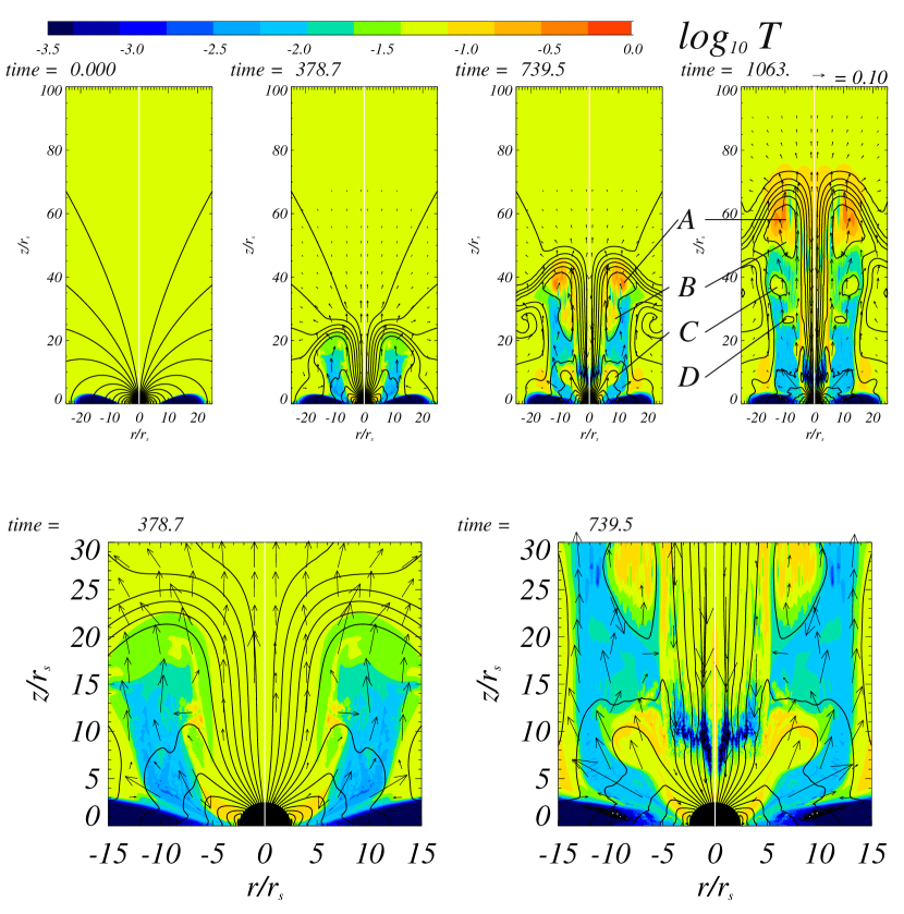
As the magnetic field lines connecting the neutron star and the disk are twisted due to the rotation of the disk, they begin to inflate in the direction 30-60 degrees from the rotation axis. The magnetic fields cease to splay out when the magnetic pressure balances with the ambient gas pressure. Afterwards, the expanding magnetic loops form a cylindrical tower of helical magnetic fields whose height increases with time. In previous MHD simulations of disk-star magnetic interaction (e.g., HSM96; GBW99 and GW99; Ustyugova et al. 2000), the tower structure was not so prominent because the ambient gas pressure was too low to confine the magnetic tower inside the computational box.
Numerical results indicate that the top interface between the tower and the external medium propagates with a speed . This propagation speed is consistent with that of the theory of magnetic towers (LB96). Disk materials are accelerated and launched along the magnetic tower. Inside the magnetic tower, current sheets are formed because magnetic field lines extend upward from the disk and then go downward to the star. Magnetic reconnection taking place in the current sheet injects hot plasmoids intermittently into the magnetic tower. In figure 1a, symbols ’B’, ’C’, and ’D’ denote such plasmoids created by magnetic reconnection. Region ’A’ is the hot region between the top of the magnetic tower and the jet terminal shock. Beside this working surface, the jet flow changes its direction away from the rotation axis and creates backflows. The radial interface between the magnetic tower and the ambient matter is stable for the growth of the Kelvin-Helmholtz instability because magnetic fields stabilize the instability.
Figure 2a shows the time evolution of the distribution of toroidal magnetic fields. Figure 2b visualizes the three-dimensional structure of magnetic field lines at t=739.5. The magnetic field lines are strongly twisted due to the rotation of the disk. Note the similarity between this figure and the analytical model of magnetic towers (figure 2 of LB96.)
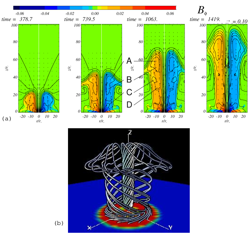
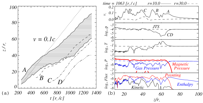
Figure 3a shows the trajectories of the working surface of the magnetic tower ’A’ and the bubbles ’B’, ’C’, and ’D’. The plasmoids are ejected intermittently with interval of the rotation period around . The maximum speed of the plasmoid moving inside the magnetic tower is about . The plasmoid ’B’ catches up with the working surface ’A’ at and merges after .
Figure 3b shows the distribution of velocity, density, temperature, gas pressure, magnetic pressure, and the vertical energy flux [kinetic energy flux , enthalpy flux , the Poynting flux ] at (inside the magnetic tower) and (outside the magnetic tower). The radius of the tower is about 20. The total pressure of the tower slightly exceeds the ambient gas pressure. It is clear that the Poynting flux dominates other fluxes inside the jets.
The density distribution has a minimum in the working surface ’A’. It corresponds to the region between the contact discontinuity (CD) and the jet terminal shock (JTS). We should remark that the bow shock ahead of the working surface is not visible because the sound speed of the ambient plasma () is larger than the propagation speed of the jet.
4. DISCUSSION
In this letter, we have demonstrated that highly collimated magnetic towers are formed along the rotation axis of the accretion disk surrounding a weakly magnetized neutron star. We also found that hot plasmoids created by the intermittent magnetic reconnections are injected into the magnetic tower (Figure 1). The magnetic towers are confined to the radius where the magnetic pressure of the expanding magnetic loops is comparable to the gas pressure of the ambient plasma.
Recently, Poynting jet, in which the energy and angular momentum are carried predominantly by the electromagnetic field, has been studied numerically by Romanova et al. (1998) and Ustyugova et al. (2000). The magnetic tower jet is a Poynting jet, because the Poynting flux dominates the energy flux of the bulk flow inside the jet in our simulation (Figure 3b). The electromagnetic extraction of angular momentum from the disk drives the accretion of the disk material. It is interesting to compare the amount of angular momentum extracted electromagnetically by the jet and the angular momentum transported inside the disk due to the magnetic turbulence driven by the magneto-rotational instability (MRI). We have to carry out three-dimensional MHD simulations to determine the MRI driven angular momentum transport rate self-consistently. We intend to report the results of such simulations in subsequent papers. Our simulation demonstrated the formation mechanism of a semi-relativistic Poynting jet around a neutron star.
We can identify the jet terminal shock (JTS) behind the working surface of the jet. Our numerical results show that a hot, low density region is created between the JTS and the discontinuity (CD) separating the jet material and the ambient plasma. The structure of the working surface of the jet is qualitatively consistent with those in previous MHD simulations of jet propagation assuming force-free magnetic fields initially uniform in the -direction (e.g., Todo et al. 1992), although the detailed structure is different because our numerical simulations started with a dipole magnetic field.
We found that hot plasmoids are injected intermittently into the magnetic tower. The injection speed of the blobs is the order of the local Alfvén speed of the reconnection region (), which is comparable to the rotation speed of the innermost region of the disk. Since this speed is faster than the propagation speed of the working surface of the jet, the blobs catch up with the working surface and release magnetic energy. Magnetic reconnection taking place in the core and in the working surface could generate high energy electrons which emit synchrotron radiation.
Let us discuss the correlation between the radio flare of the core and the lobe observed in Sco X-1. Magnetic reconnection taking place in the core will eject hot plasmoids, which subsequently release magnetic energy again at the working surface of the magnetic tower. This event can be observed as the lobe flares correlated with the core flares. In our simulations, however, the maximum speed of the hot plasmoids () is smaller than the speed estimated from the time lag between the core flare and the lobe flare. This discrepancy may be resolved if the Alfvén speed inside the magnetic tower is faster than that attained in our simulation. This happens when the plasma density inside the magnetic tower is lower than the ambient plasma. Plasma heating due to magnetic reconnection helps increasing the Alfvén speed and ejection speed of hot bubbles.
We should point out the limitation of using non-relativistic MHD. Although we take into account general relativistic effects by using a pseudo-Newtonian potential, we solved Newtonian MHD equations by neglecting special relativistic corrections. By extending our work to fully general relativistic MHD, we will be able to simulate models having Alfvén speed closer to the light speed.
The work presented here is the first numerical simulation which clearly shows the formation process of the axisymmetric magnetic tower and semi-relativistic jets. We expect that semi-relativistic jets observed in some XRBs are driven by the magnetic interaction between the dipole magnetic field of a weakly magnetized neutron star and its accretion disk. 3-D simulations are necessary to study the stability of magnetic towers against non-axisymmetric perturbations. We would like to report the results of such simulations in the near future.
References
- Blandford & Payne (1982) Blandford, R. D. & Payne, D. G. 1982, MNRAS, 199, 883
- Fender et al. (1998) Fender, R., Spencer, R., Tzioumis, T., Wu, K., van der Klis, M., van Paradijs, J., & Johnston, H. 1998, ApJ, 506, L121
- Fomalont, Geldzahler, & Bradshaw (2001) Fomalont, E. B., Geldzahler, B. J., & Bradshaw, C. F. 2001a, ApJ, 553, L27
- Fomalont, Geldzahler, & Bradshaw (2001) Fomalont, E. B., Geldzahler, B. J., & Bradshaw, C. F. 2001b, ApJ, 558, 283
- A. P. Goodson, K. Borhm, and R. M. Winglee (1999) Goodson, A. P., Böhm, K., & Winglee, R. M. 1999, ApJ, 524, 142
- A. P. Goodson and R. M. Winglee (1999) Goodson, A. & Winglee, R. M. 1999, ApJ, 524, 149
- M. R. Hayashi, K. Shibata, and R. Matsumoto (1996) Hayashi, M. R., Shibata, K., & Matsumoto, R. 1996, ApJ, 468, L37
- Hjellming & Johnston (1981) Hjellming, R. M. & Johnston, K. J. 1981, Nature, 290, 100
- Lovelace, Romanova, & Bisnovatyi-Kogan (1995) Lovelace, R. V. E., Romanova, M. M., & Bisnovatyi-Kogan, G. S. 1995, MNRAS, 275, 244
- Lynden-Bell & Boily (1994) Lynden-Bell, D. & Boily, C. 1994, MNRAS, 267, 146
- Lynden-Bell (1996) Lynden-Bell, D. 1996, MNRAS, 279, 389
- Martí, Paredes, & Peracaula (2000) Martí, J., Paredes, J. M., & Peracaula, M. 2000, ApJ, 545, 939
- R. Matsumoto, Y. Uchida, S. Hirose, K. Shibata, M. R. Hayashi, A. Ferrari, G. Bodo, and C. Norman (1996) Matsumoto, R., Uchida, Y., Hirose, S., Shibata, K., Hayashi, M. R., Ferrari, A., Bodo, G., & Norman, C. 1996, ApJ, 461, 115
- Mioduszewski et al. (2001) Mioduszewski, A. J., Rupen, M. P., Hjellming, R. M., Pooley, G. G., & Waltman, E. B. 2001, ApJ, 553, 766
- Romanova et al. (1998) Romanova, M. M., Ustyugova, G. V., Koldoba, A. V., Chechetkin, V. M., & Lovelace, R. V. E. 1998, ApJ, 500, 703
- B. Paczynsky and P. J. Wiita (1980) Paczyńsky, B. & Wiita, P. J. 1980, Astronomy and Astrophysics, 88, 23
- Shibata & Uchida (1986) Shibata, K. & Uchida, Y. 1986, PASJ, 38, 631
- Todo, Uchida, Sato, & Rosner (1992) Todo, Y., Uchida, Y., Sato, T., & Rosner, R. 1992, PASJ, 44, 245
- Uchida & Shibata (1985) Uchida, Y. & Shibata, K. 1985, PASJ, 37, 515
- Ustyugova et al. (2000) Ustyugova, G. V., Lovelace, R. V. E., Romanova, M. M., Li, H., & Colgate, S. A. 2000, ApJ, 541, L21