Retroactive Coherence
Abstract
In gravitational microlensing, interference visibility is established when the spectral resolution of the observation is less than the reciprocal of the time delay difference. Using high resolution spectroscopy fringes will be visible at large path differences, even when the source emission is incoherent. This is possible because coherence can be established after interference has already occurred. Results of a laboratory test are presented which demonstrate this retroactive establishment of coherence.
1 Introduction
Interference can occur when there are two paths for light propagation from a source to an observer. In gravitational microlensing (Alcock, et.al. (2000), Wozniak, et.al. (2001), Derue, et.al. (1999)) wavetrains from a point on the source star travel on two paths, and the wave amplitudes are combined before the light is detected. The lensing geometry has the potential to produce interference, and applications of gravitational lensing interference have been considered for wavelength regimes from radio waves to gamma rays (Mandzhos (1981), Schneider and Schmid-Burgk (1985), Deguchi and Watson (1988), Peterson and Falk (1991), Gould (1992), Stanek, Paczynski and Goodman (1993), Ulmer and Goodman (1995)). As many of these authors note, interference visibility will be diminished if the difference of the length of the two paths exceeds the coherence length of the light.
The light sources in gravitational microlensing are incoherent. In many microlensing examples the light sources are stars and stellar photospheres emit primarily blackbody radiation. The temporal coherence length of this light is , where is the speed of light, is the coherence time and is the half-power bandwidth of the source emission spectrum. Because of the large bandwidth of the blackbody spectrum, the coherence length is about equal to the peak wavelength. Blackbody emission is often labeled “incoherent”.
Blackbody emission can be modeled as a continuous stream of short wavepackets. Figure 1 shows wavepackets of length traveling on two paths from source to observer around a lensing mass. Because the wavepackets do not overlap at arrival, the short coherence length of the light would seem to indicate that gravitational lensing interference is undetectable except in cases where the path length difference amounts to just a few wavelengths. However, this is not correct, as the experiment described below demonstrates.
Coherence can be established retroactively. After incoherent light has passed through the interference apparatus (in the lab or in the Universe), it can be filtered to a narrow bandwidth and that filtered light will have a new, longer coherence length. This allows gravitational microlensing interference to be observed for large path length differences.
In this Letter I present results of a laboratory experiment, carried out using a Michelson interferometer, which demonstrates retroactive coherence.
2 Two Path Coherence
An analysis of partial coherence for two path geometries is presented in Born and Wolfe (1980). I adapt their analysis to the present purpose.
To describe the degree of interference seen in the patterns formed by his interferometers Michelson defined a quantity called the interference visibility . Here the maximum and minimum of the intensity and are taken as the path length difference varies. ranges from 0 to 1, and generally has a maximum at zero path difference.
For two-path gravitational microlensing, or for light that passes through a Michelson interferometer, the detected intensity is
| (1) |
where and are the intensities on the two paths, is a complex function describing the time variation of the arriving field strength on the shorter path, and is the same function shifted in time by the path delay difference. is normalized, i.e. , and assumed to be stationary. is the duration of the observation, the time over which the intensity is averaged, and is taken to be much longer than and .
The total intensity is then
| (2) |
The last term describes the interference is also called the real part of the complex degree of coherence .
For an optical frequency band centered at the magnitude of the degree of coherence is related to the interference visibility by .
The autocorrelation of the wave amplitude is the fourier transform of the power spectral density of the light and the coherence length is the width of the function . This means that decreasing the bandwidth of the observation, i.e. forcing to zero outside a narrow range of frequencies, increases the coherence length and makes interference visible at large path length differences. The experiment described below shows that this is true even when the bandwidth restriction occurs after the light has passed through the interference apparatus.
3 Laboratory Analog of Lensing Interference
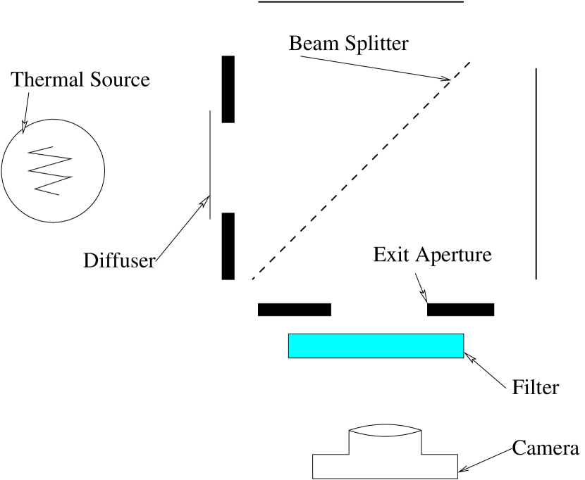
I set up a laboratory analog of gravitational lensing interference using a Michelson interferometer, as shown in figure 2. In the experiment light from a laboratory thermal source arrives at a partially reflecting beam splitter which divides the light among two paths. These paths are the two orthogonal arms of the interferometer. At the ends of the arms mirrors return the light to the beam splitter with a path length difference that can be adjusted. The beam splitter recombines the light before it passes through the exit aperture.
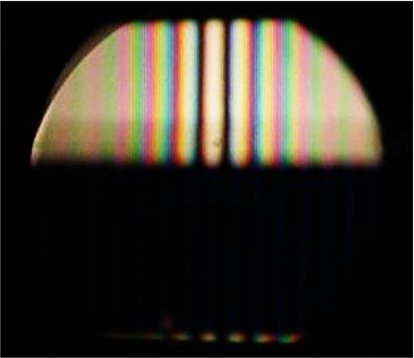
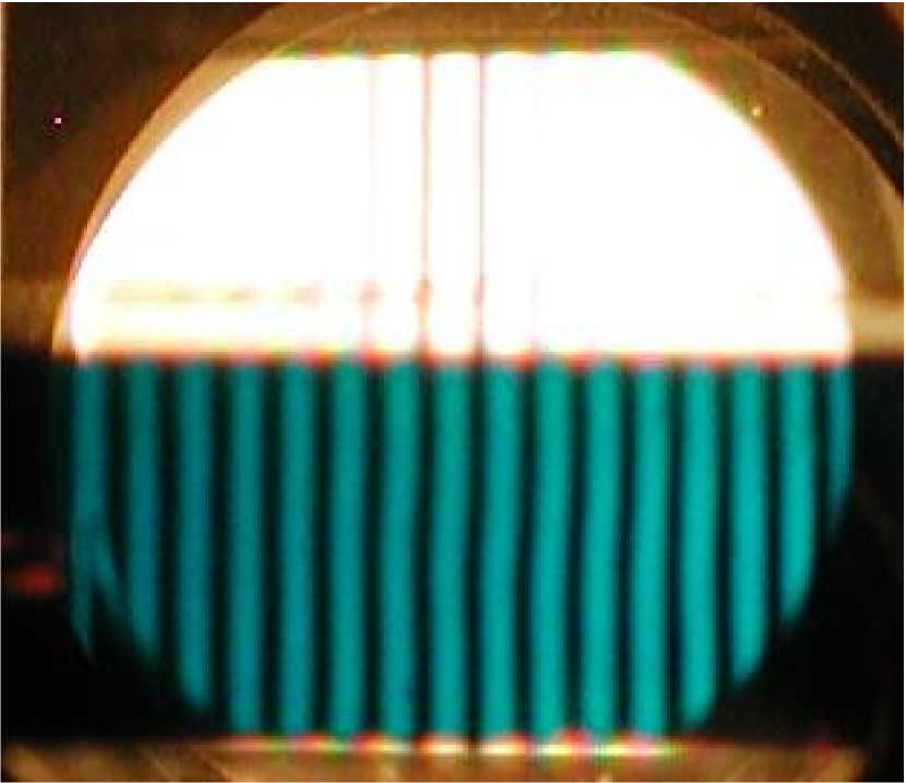
Filtering the light restores interference visibility. In gravitational lensing the path length varies with time because of relative motion among the source, lensing masses, and the observer. In the Michelson interferometer, the path lengths are stable but the interferometer can be adjusted to give various path lengths through various parts of the instrument. I tilted one mirror slightly so zero path length difference occurs only at a line dividing the pattern vertically. The pattern is also divided horizontally. The top half of the exit aperture of the interferometer is unblocked and here the full bandwidth of the thermal source contributes to the interference pattern. The bottom half of the exit aperture is covered by a narrow-band () filter. In figure 3 the results of the experiment are displayed. For white light the visibility falls almost to zero within a few fringes. For filtered light the visibility remains near one for the entire width of the pattern.
Considering the frequency domain it is easy to see how coherence is restored through bandwidth restriction: the white light interference pattern is composed of many narrow-band patterns overlaid. The spacing of the fringes is proportional to wavelength. For all wavelengths, the patterns are aligned in the center of the image, at zero path difference. The central few fringes have high visibility but, away from the center of the image, the pattern develops colored stripes, as red and blue fringe patterns separate in phase. At the edge of the pattern the visibility has fallen nearly to zero because of cancellation, among the various wavelengths, of constructive and destructive interference. By selecting a narrow range of frequencies cancellation is avoided and the interference becomes visible across the entire field. This is shown in the right panel of figure 3.
In the time domain a puzzle remains: how can short coherence length wave packets, which don’t overlap as they exit the interferometer, create visible interference at large path length differences? The answer is that the filter stores multiply delayed copies of the wave train incident upon it. Interference occurs among these copies. Light storage in a filter is illustrated in figure 4.
4 Discussion
In the experiment described here a single narrow filter is used to restrict the passband of the observation. Most of the optical power from the source is blocked by this filter. In a gravitational microlensing observation a spectrophotometer could be used instead of a filter. This would divide the spectrum into many narrow passbands, each acting as a narrow filter. This allows all the optical power to be used in the observation. For a spectrophotometer the coherence time is the reciprocal of the frequency resolution.
Although temporal coherence can be increased by using high spectral resolution, limited lateral spatial coherence remains a factor reducing lensing interference visibility for most geometries studied so far. As described in the references above, the path length difference varies from point to point across the disk of a source star. The total variation is generally many wavelengths, and this substantially reduces interference visibility.
Occasionally, microlensing events include caustic crossings. At the first crossing two new, high magnification paths appear. These paths have the same length at first so the size of the laterally coherent region (Jaroszynski and Paczynski (1995), Gould and Gaudi (1997) ) can cover a much larger part of the source disk than in the more common Schwarzschild case.
A Michelson interferometer is useful, not just as a laboratory analog of gravitational lensing interference, but also as a tool for observation of the effect. Microlensed light, collected with a telescope, can be passed through a Michelson interferometer before detection. Then, if the interferometer path length difference matches the lensing path length difference, the two arriving wavepackets seen in figure 1 can be realigned, and bandwidth reduction of visibility can be avoided. For slight mismatches of the two path length difference the required bandwidth for full visibility is .
Even though a complex representation of the wave amplitude is used in this discussion of interference, and even though the uncertainty principle applies to the coherence time, the effects described here are classical rather than quantum mechanical. No use is made, in this analysis, of photon quanta.
The use of high resolution spectroscopy establishes coherence retroactively, allowing gravitational microlensing interference to be visible for path length differences many times larger than the wavelength of the light.
References
- Alcock, et.al. (2000) Alcock, C., et.al 2000, ApJ, 542, 281
- Born and Wolfe (1980) Born and Wolfe
- Deguchi and Watson (1988) Deguchi, S. and Watson, W. D. 1986, ApJ, 307, 30
- Derue, et.al. (1999) Derue, F., et.al. 1999, A&A, 351, 87
- Gould (1992) Gould, A. 1992, ApJ, 386, 5
- Gould and Gaudi (1997) Gould, A. and Gaudi, B.S. 1997, ApJ, 486, 687
- Jaroszynski and Paczynski (1995) Jaroszynski, M. and Paczynski, B. 1995, ApJ, 455, 443
- Mandzhos (1981) Mandzhos, A. V. 1981, Soviet Astron. Lett., 7, 213
- Peterson and Falk (1991) Peterson, J. B. and Falk, T. 1991, ApJ, 374, 5
- Schneider and Schmid-Burgk (1985) Schneider, P. and Schmid-Burgk, J. 1985, A&A, 148, 369
- Stanek, Paczynski and Goodman (1993) Stanek, K. Z., Paczynski, B. and Goodman, J. 1993 ApJ, 413, 7
- Ulmer and Goodman (1995) Ulmer, A. and Goodman, J. 1995, ApJ, 442, 67
- Wozniak, et.al. (2001) Wozniak, P. R., et.al. 2001, Acta Astron., 51, 175