Simulation studies of a high-repetition-rate electron-driven surface muon beamline at SHINE
Abstract
A high-repetition-rate pulsed muon source operating at approximately 50 kHz holds the potential to improve the sensitivity of various particle physics and material science experiments involving muons. In this article, we propose utilizing the high-repetition-rate pulsed electron beam at the SHINE facility to generate a surface muon beam. Our simulation studies indicate that an 8 GeV, 100 pC charge pulsed electron beam impinging on a copper target can produce up to muons per pulse. Beamline optimization results demonstrate that approximately 60 surface muons per electron bunch can be efficiently transported to the end of the beamline. This translates to a surface muon rate of /s when the pulsed electron beam is operated at 50 kHz, which is comparable to existing muon facilities. This high-repetition-rate pulsed muon beam, with its ideal time structure, represents a unique and pioneering effort once constructed. It serves as a model for building cost-effective muon sources at existing electron machines with GeV electron energies. The main challenge of positron removal is also discussed.
I Introduction
Muons play a pivotal role in various scientific domains, including particle physics, nuclear physics, and condensed matter physics [1, 2], due to their unique properties and interactions. The increasing importance and demand for muons in these fields have led to a growing emphasis on their production and application. Today, muons can be generated in large quantities by bombarding target materials with intense proton beams from advanced accelerator facilities. This process primarily involves the production of pions through strong nuclear interactions, which then decay into muons.
Of particular interest are “surface muons”, which originate from pions decaying near the target surface. These muons exhibit nearly 100% polarization due to the parity-violating weak decay of pions, and their momentum remains almost monochromatic at approximately 29.8 MeV/c. These distinctive properties make surface muons highly valuable for a wide range of experimental studies. Current state-of-the-art muon facilities could deliver up to /s usable surface muon beam to the experimental area of muon spin rotation (SR) experiments.
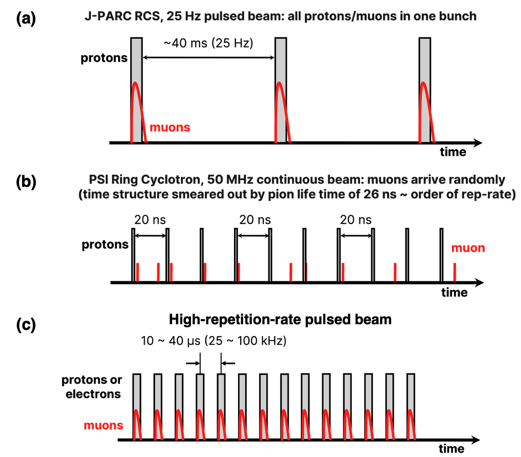
However, the repetition rates of muon beams currently available at these facilities are non-ideal and essentially limited to two modes: pulsed mode (25-50 Hz, e.g., J-PARC) and continuous mode (e.g., PSI). Considering that a typical muon experiment lasts for about ten muon lifetimes, current operation modes are not ideal for those muon experiments [3, 4, 5]. For example, the duty cycle is low in the pulsed mode, and the continuous mode is disadvantageous in terms of statistics. The typical time structure of currently available muon beams is shown in Fig.1. Many authors have mentioned that the most suitable muon source for experiments — such as SR [3], muon electric dipole moment [4], muonium to anti-muonium conversion [5], muon lifetime [6], and muon spin force [7] — operates in a pulsed mode with a repetition rate of several tens of kHz, as shown in Fig. 1(c).
To meet this demand, improvements to the time structure in muon production using existing proton beams are being considered. There are several plans to generate proton beams with a time structure suitable for muon sources with ideal repetition rates. For instance, the development of a non-scaling fixed-field alternating gradient (FFAG) proton accelerator operating at frequencies of a few kHz has been proposed [8, 9]; in the high-energy beam transport of a spallation neutron source (SNS) accelerator, proton pulses with a repetition rate of 50 kHz have been successfully extracted based on laser neutralization of a 1 GeV hydrogen ion (H-) beam [10]; the proton beam for the Mu2e experiment at Fermilab has a proton bunch repetition rate of 0.59 MHz, which is achieved by resonant slow extraction of the proton bunches from the delivery ring [11]. However, these attempts have not yet been realized or are not versatile enough.
On the other hand, muon sources utilizing electron beams have recently emerged as a promising alternative to traditional proton-driven sources. Nagamine notably proposed the use of electron microtrons for a compact SR beamline [12]. Recent advancements have established high-repetition-rate (kHz to MHz) electron beams generated by linear accelerators. When combined with a muon production target, these electron beams can create muon sources with an optimal time structure.
Unlike proton beam-driven sources, electron beam-driven schemes produce muons as tertiary beams through photo-nuclear processes. In this method, Bremsstrahlung generates real photons, which subsequently induce photo-excitation of nuclei, leading to pion production and subsequently decay muon. Additionally, muons can be produced via the Bethe-Heitler pair production process, although this method has a lower production cross-section. Despite this, the Bethe-Heitler process yields higher-energy muons with better directionality, as it bypasses pion production and decay stages.
This concept is particularly attractive because it does not require a dedicated facility and can be implemented at any facility that produces electron beams for various research applications. It is especially compatible with synchrotron radiation and X-ray free electron laser (XFEL) facilities, where GeV electron beams are typically dumped, thus offering a sustainable and innovative approach to muon production.
Furthermore, recent advances in laser wakefield acceleration (LWFA) technology have reduced the size of electron accelerators from kilometers to meters, further driving research into compact muon source concepts. The anticipated availability of high-repetition-rate femtosecond multi-PW lasers has fueled this research momentum. However, most studies utilizing laser technology [13, 14, 15] have focused on generating high-energy muons through the pair production process rather than low-energy muons for SR applications.
In this article, we explore the use of high-repetition-rate electron beams from the ”Shanghai High repetition rate XFEL and Extreme Light facility” (SHINE) [16] as a driver for muon sources. This cutting-edge facility, currently under construction in Zhangjiang, Shanghai, will feature a continuous-wave (CW) superconducting electron linac capable of delivering an 8-GeV bunched electron beam with a bunch charge of 100 pC and a repetition rate of up to 1 MHz, resulting in an average current of 100 A. The beamline will include three undulator lines capable of generating hard X-rays up to 25 keV, and a fast kicker system will distribute electron bunches, supplied at up to 1 MHz, to the respective beamlines and beam dumps. More information about the current layout can be found at [17].
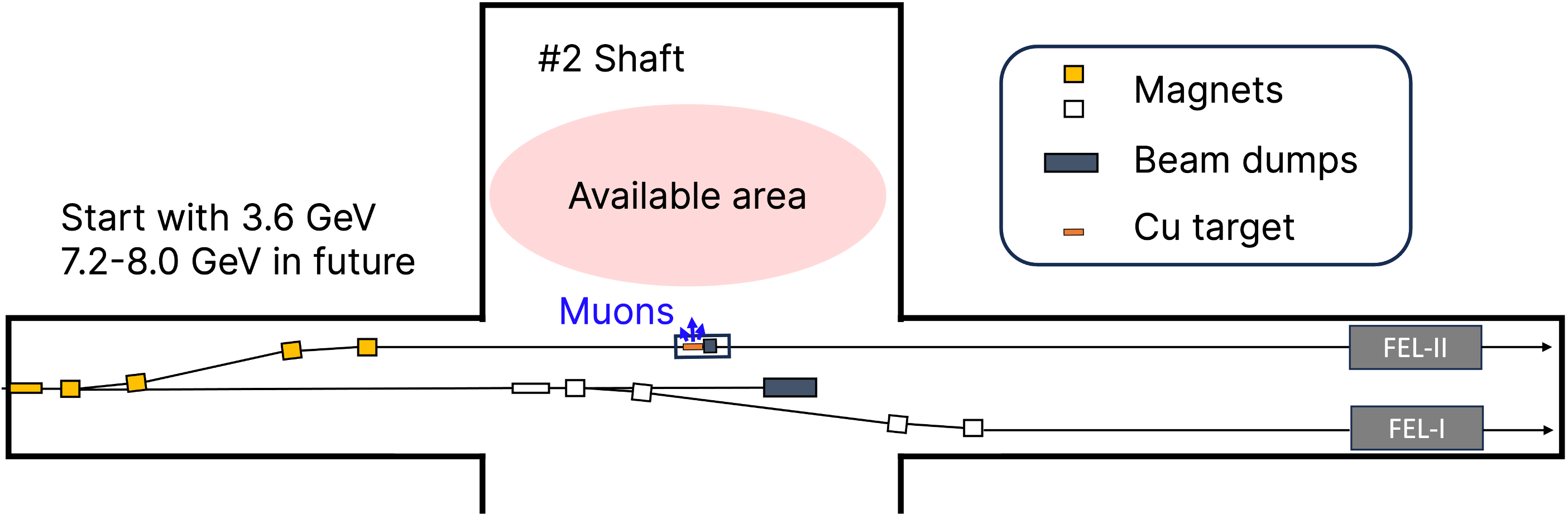
The interaction between the electron beam and either the beam dump or a pre-beam dump thin target holds the potential for producing muons and other secondary particles [18]. Figure 2 illustrates the configuration of the electron beamline at the SHINE facility and provides a conceptual diagram of the muon source using this beam.
This paper outlines the concept of a high-repetition-rate muon source and a transport beamline for the muon beam, utilizing the high-repetition electron beam from the SHINE facility. Additionally, we discuss the expected surface muon beam intensity and its potential applications.
II Muon production target
II.1 Material selection
For the production target material, we compared graphite, widely used in proton-driven muon sources, with copper and tungsten, which have been suggested in previous studies, to evaluate their effectiveness in muon production using an electron beam. Bremsstrahlung and pair production induce electromagnetic showers, which significantly influence muon production by the electron beam. Therefore, understanding the properties of these showers is critical. The characteristics of electromagnetic showers in different target materials, based on SHINE’s design parameters (8 GeV, 100 A), are summarized in Table 1. We evaluated three materials based on key properties: the depth of the shower maximum (), the heat load () at this depth, and the depth at which 99% of the beam energy is absorbed ().
| Materials | Graphite | Cu | W |
|---|---|---|---|
| 6 | 29 | 74 | |
| 12 | 64 | 184 | |
| [g/cm3] | 1.82 | 8.94 | 19.25 |
| [mm] | 839 | 73.9 | 20.7 |
| [kW/cm] | 0.24 | 3.26 | 13.2 |
| [mm] | 3090 | 281 | 79.8 |
Due to its energy absorption characteristics, graphite necessitates an extended length for complete electromagnetic shower development. This increased target dimension is suboptimal for surface muon production, as the initial beam size correlates directly with target dimensions. While tungsten enables electromagnetic shower development over shorter distances, it presents significant thermal management challenges due to concentrated heat loads in thin targets. Copper emerges as the optimal balance, facilitating electromagnetic shower development over moderate lengths while generating approximately 25% less heat load compared to tungsten. Furthermore, copper’s superior thermal conductivity characteristics make it particularly suitable for managing the thermal stress induced by high-repetition, high-energy electron beams. The material’s well-established manufacturing processes and cost-effectiveness, combined with these favorable physical properties, position copper as the prime candidate for high-repetition muon production targets, despite certain remaining technical challenges.
Based on these considerations, we will proceed with copper as the target material for further studies.
II.2 Target geometry
The thin slab targets used at PSI [19] and in the CSNS target design studies [20] are considered standard for proton-based muon sources. These facilities must maintain a material budget in the proton beam and scale the target length accordingly due to downstream spallation neutron sources. Occasionally, targets need to be tilted slightly (approximately 5 degrees) to increase the target size while maintaining the interaction length. Thin targets pose challenges in heat management, sometimes necessitating rotating targets, which can introduce additional mechanical issues.
In contrast, our muon source utilizes an electron beam that is dumped directly, eliminating the need for a thin target to maintain the material budget. To ensure radiation safety beyond the tunnel’s limited shielding thickness, it is essential to provide comprehensive local shielding around the high-power target. This configuration allows the use of a box-shaped thick target and a beam dump without significant disadvantages, facilitating cooling by increasing the target’s heat capacity.
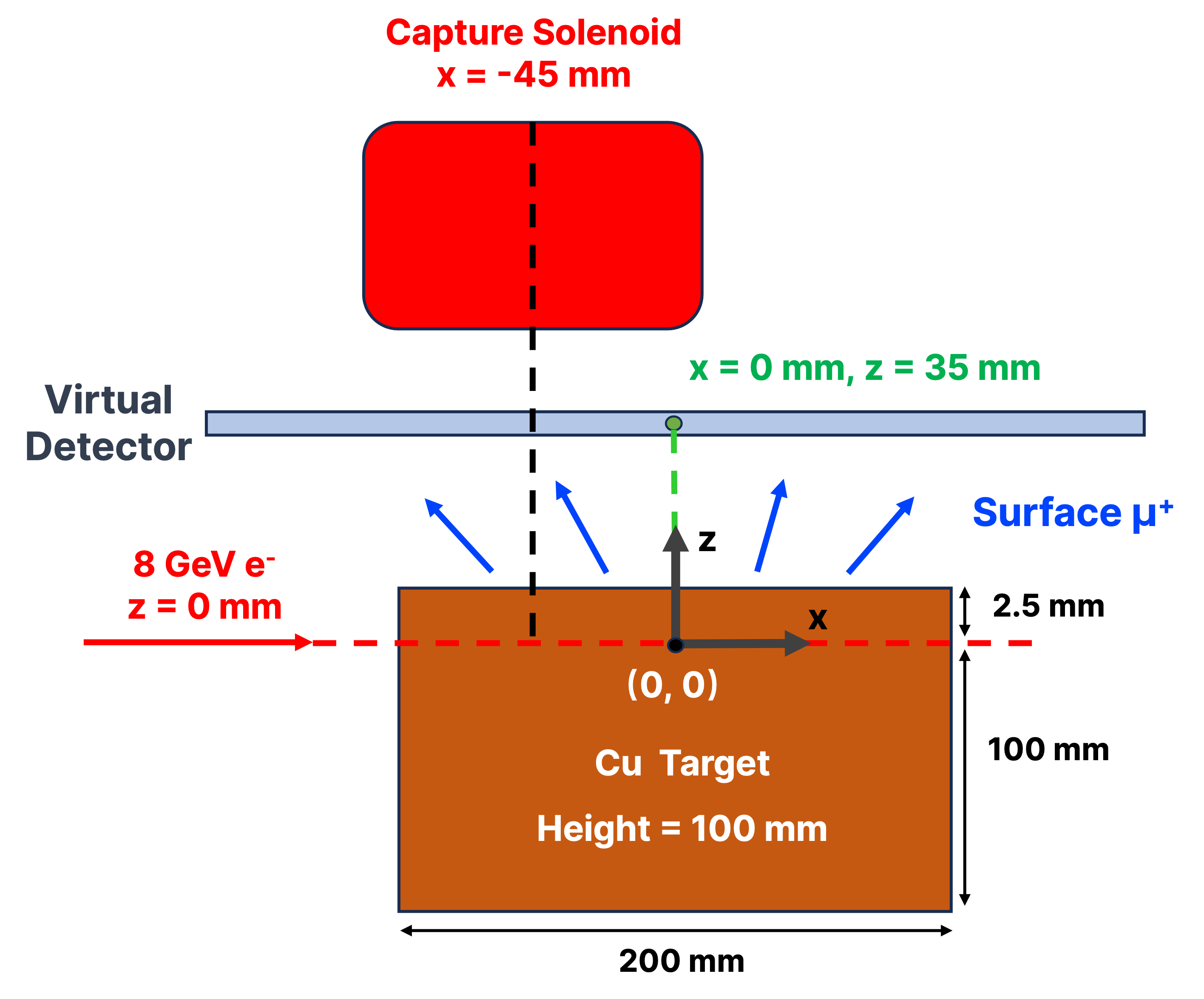
The beam position and target length were optimized to maximize the surface muon yield. Particle interactions and transport processes in the target were simulated using FLUKA code, version 4-4.0 [21] to estimate the yield. The simulation assumed an 8 GeV, 100 pC/bunch electron beam with an RMS beam size of 2 mm impinged on the target 111The the typical electron beam spot from the SHINE superconducting linac is about (10 ). However, at this small beam size, it will produce excessively high power density. At a repetition rate of 50 kHz, the copper target may not endure the thermal load. The 2 mm beam spot assumed here is based on a recent SHINE beam dump study [42], and this number will be optimized with a more focused study based on the target’s thermal engineering design. To achieve a millimeter-sized beam spot, a beam spoiler system can be utilized. Such a spoiler system is commonly employed at the end of the SLAC linac to degrade the beam at the A-line and ESA [43].. A virtual detector, measuring 100 cm 100 cm, was positioned 35 mm perpendicular to the electron beam to record muon counts. The target configurations in the simulation are shown in Fig. 3.
A variance reduction technique, specifically mean-free path biasing (LAM-BIAS), was introduced into the computational model to improve efficiency. An energy threshold of 10 MeV was set to ignore the production and transport of low-energy electrons, positrons, and photons, which do not contribute to muon production, enhancing calculation speed. Each target geometry simulation involved electrons, with the biasing method shortening the photon hadronic interaction length by a factor of 0.02 to improve statistics. Results were scaled to correspond to the number of electrons in one bunch.
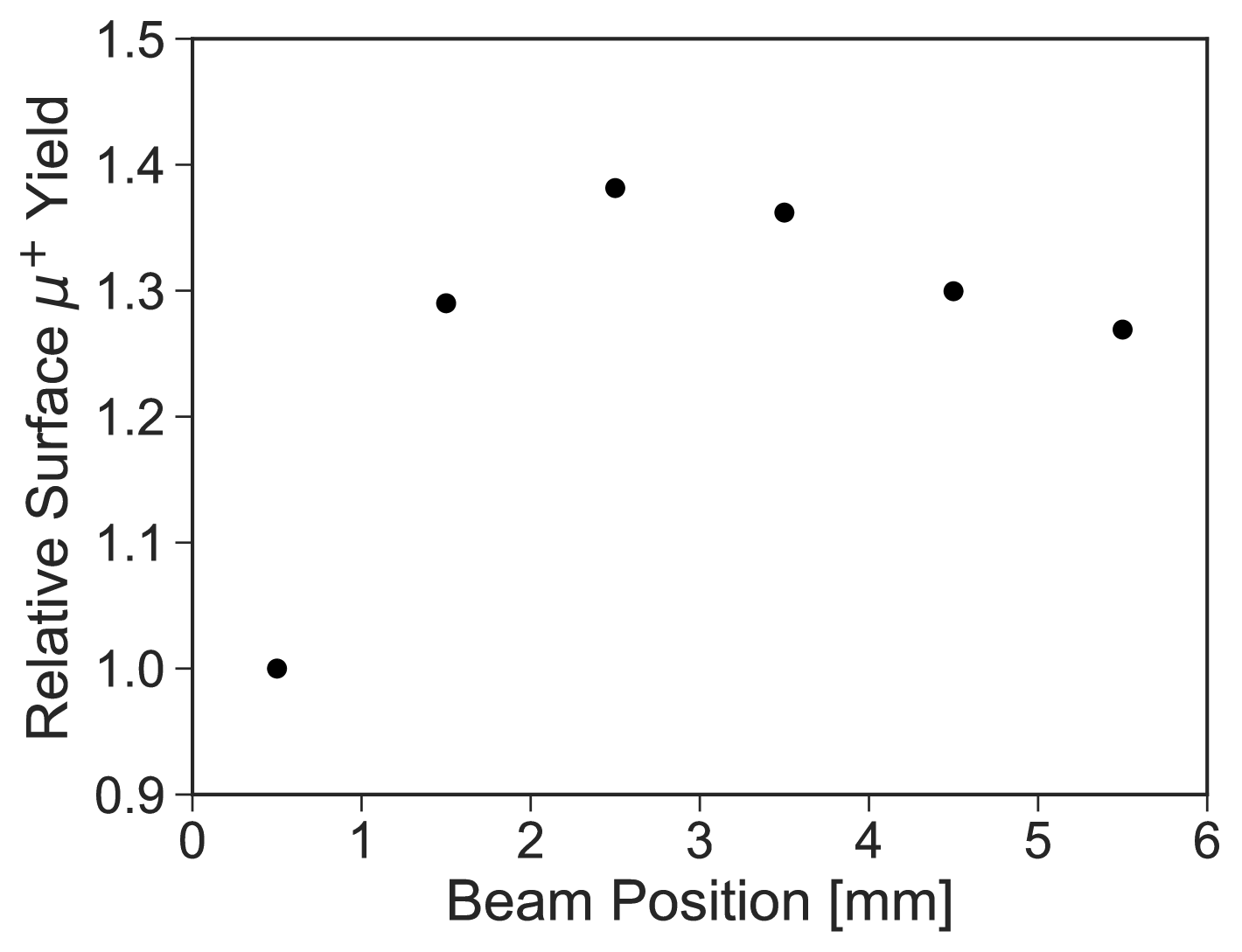
The beam position was varied from 0.5 to 5.5 mm away from the target surface in 1 mm increments. Figure 4 shows the surface muon yield at each point normalized by the yield at 0.5 mm. The yield increased rapidly until the beam position reached 2.5 mm, beyond which it gradually decreased. This suggests that up to 2.5 mm, the increased beam area on the target enhances muon yield, but beyond this thickness, it becomes too thick for muons to exit the surface.
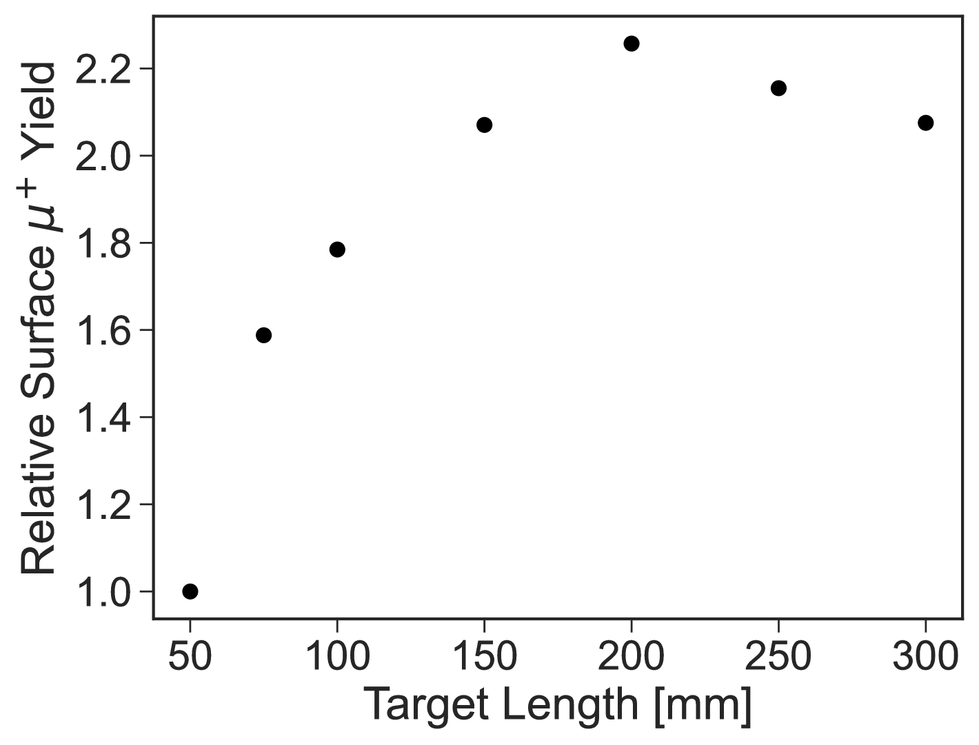
With the beam position fixed at 2.5 mm, the target length along the beam direction was scanned, examining seven points between 50 mm and 300 mm. As shown in Fig. 5, surface muon yield increased up to a target length of 200 mm before decreasing. Notably, the enhancement from 50 to 75 mm was substantial. As shown in Tab. 1, is 73.9 mm, suggesting significant benefits from increasing the target length up to this point. Given that is 281 mm, extending the target length can further increase yield, with a 200 mm target length set as our baseline based on these findings.
III Surface muon beamline
To optimize the muon production target parameters, we employed FLUKA for its high computational efficiency. Since FLUKA isn’t designed for detailed particle tracking simulation, we used g4beamline [23]—a code specializing in particle transport and optics—to generate initial particle distributions for beamline design studies. This approach allowed us to seamlessly transition to subsequent g4beamline studies.
III.1 Surface muon yield
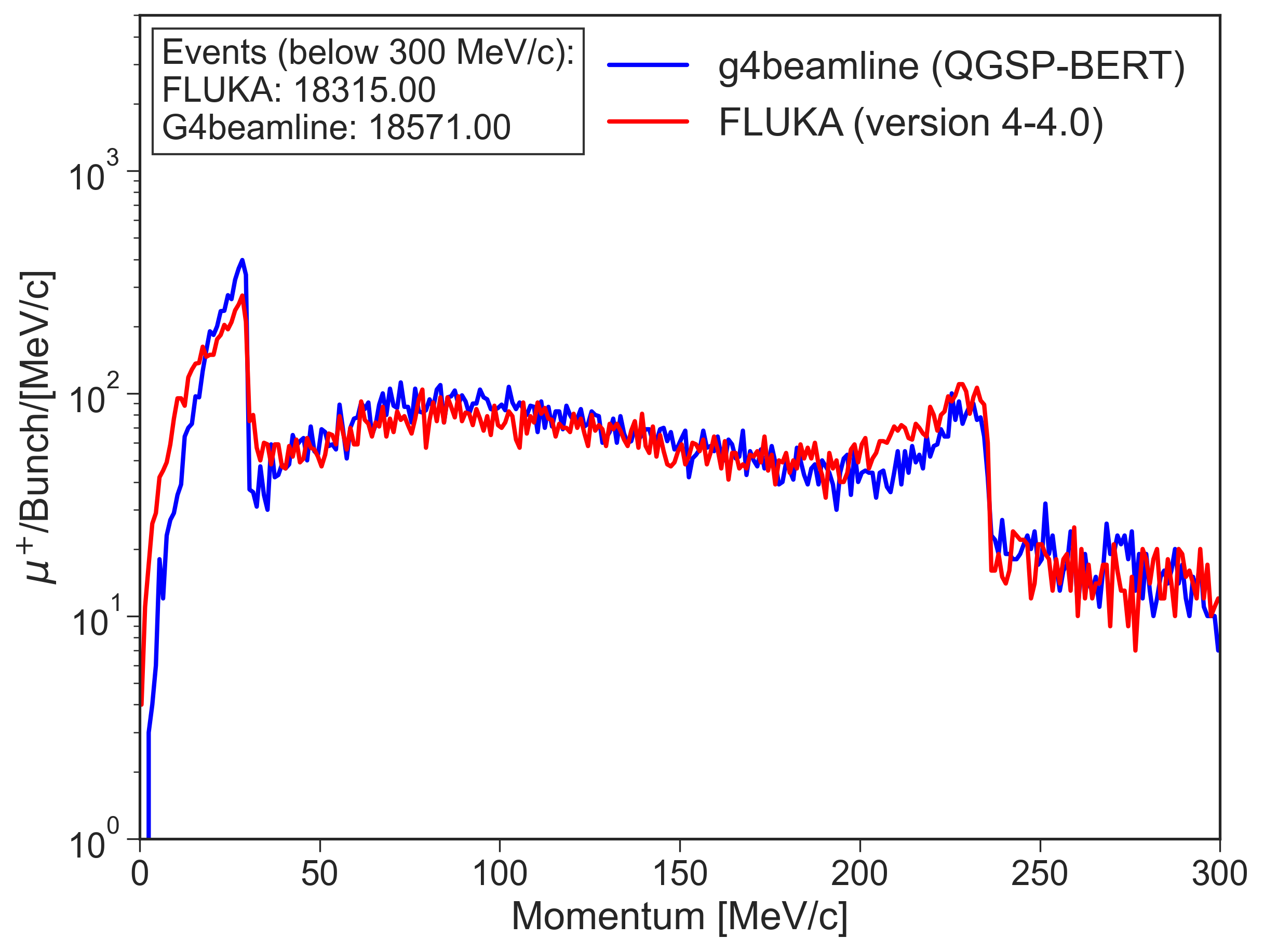
Firstly, we thoroughly investigated the surface muon yield using optimized baseline target designs with g4beamline. The physics model used was QGSP-BERT with a simulation setup akin to the FLUKA setup (a virtual detector is placed near the side of the target). The yield of positive muons (below 300 MeV/c) from photo-nuclear processes was estimated at approximately per bunch. Fig. 6 shows the momentum distribution of these photo-nuclear-generated muons along with other major positively charged particles. Comparing muon yields between the two codes showed agreement within 2% for momenta below 300 MeV/c, and within 30% for the 25-30 MeV/c momentum region (see detail in Appendix).
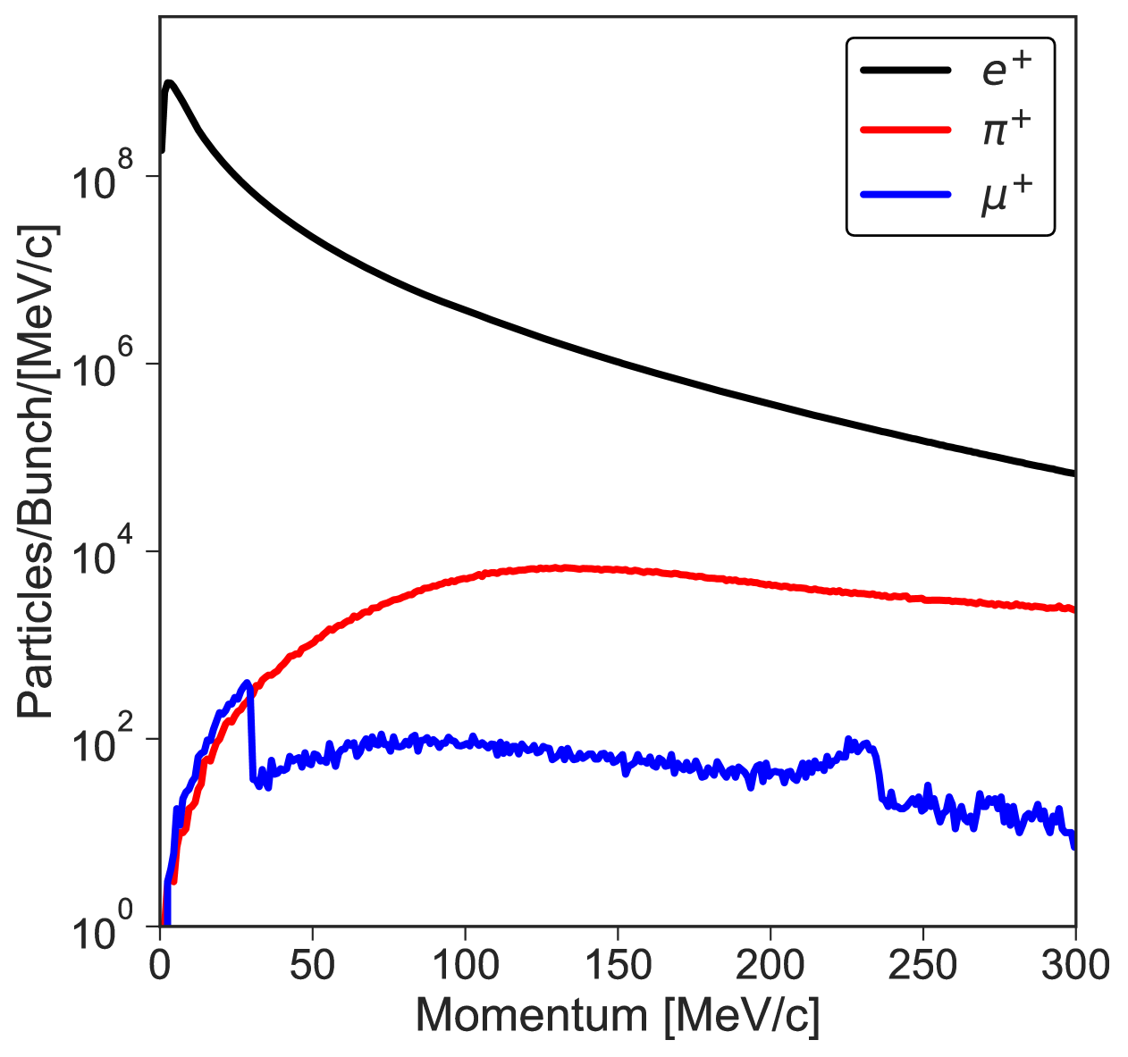
Muons exhibit a broad energy distribution, decreasing from low to high energy regions. Notably, the momentum distribution shows two distinct peaks, corresponding to the production of surface muons from the decay of pions and kaons, with momentum peaks around 30 MeV/c and 230 MeV/c, respectively. The yield of surface muons derived from pion decay in the 25 to 30 MeV/c range is approximately muons per bunch. Operating at a frequency of 50 kHz, this translates to an intensity of /s. Although the muon yield per bunch is relatively low, the high repetition rate compensates for this, resulting in an overall intensity per second comparable to existing proton beam-driven muon sources.
Surface muons produced from kaon decays offer a unique opportunity to investigate extremely dense materials or materials under hydrostatic pressure due to their high penetrating power, allowing for deeper examination of such materials [24].
In addition to muon-related experiments, pulsed positrons can be collected and transported to various dedicated terminals for applications in positron annihilation spectroscopy (PAS), which are associated with microstructural defects in materials [25, 26]. These terminals include positron lifetime measurements, Doppler broadening measurements, age-momentum correlation measurements, and angular correlation measurements. The exceptionally high intensity of the positrons can be effectively utilized to generate slow positron beams with adjustable energy, thereby meeting the significant demands in defect characterization within thin films and surface materials interfaces.
III.2 Characteristics of the Initial Muon Beam
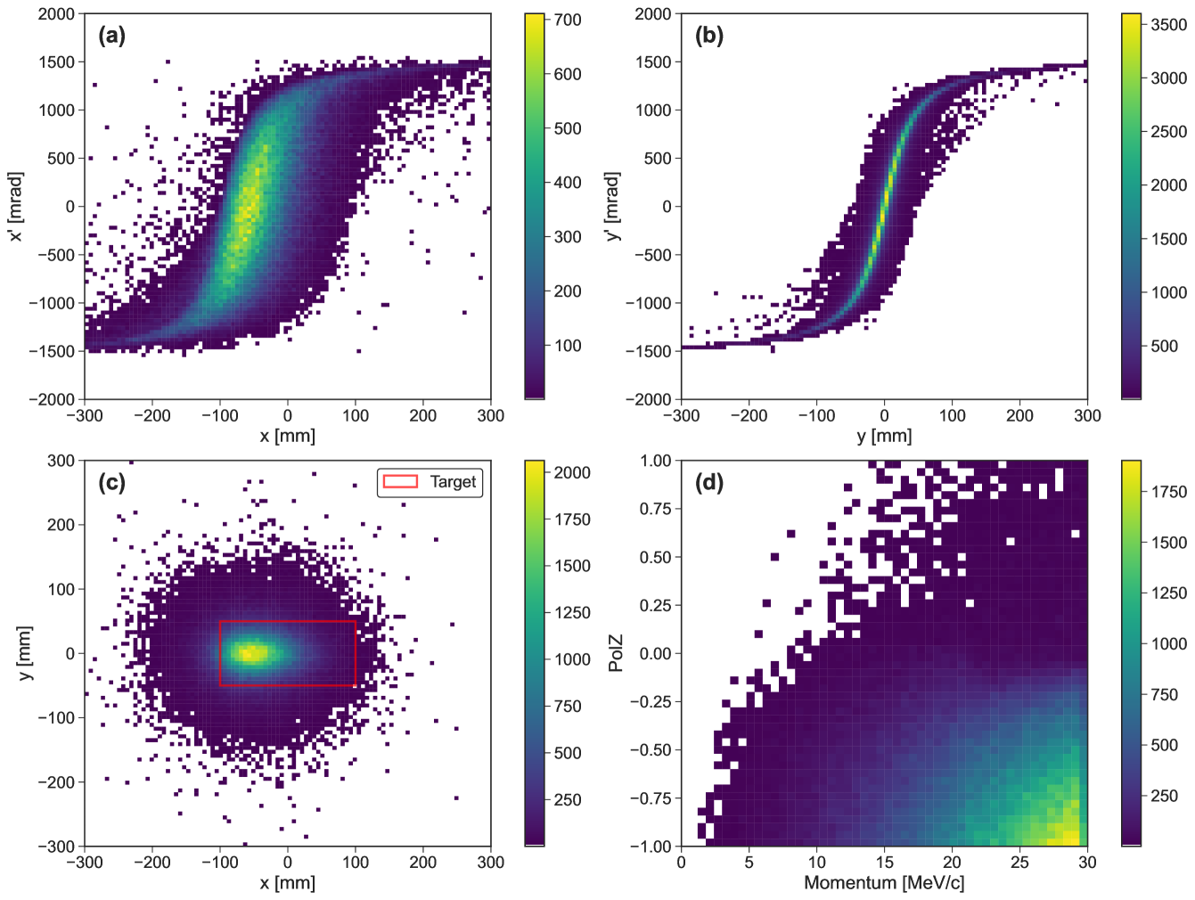
The characteristics of the muon beam emerging from the target were then analyzed using the virtual detector. Figure 7 illustrates the horizontal and vertical phase space (, ), the real space () of the beam, and the polarization dependence on momentum. From Fig. 7 (Bottom right), it is evident that the muons with the highest polarization relative to the centerline-z axis possess the highest momentum, as these high-momentum muons are predominantly forward-going and abundant.
Selected phase space parameters of the muon beam are summarized in Tab. 2. Given that the incident electron beam is aligned along the -axis, the muon beam exhibits asymmetry in the horizontal plane, with a mean horizontal position shift of approximately -45.2 mm from the center of the target. To maximize acceptance, the solenoid’s cross-sectional center is aligned with the centroid of the beam.
| Parameters | Value |
|---|---|
| Mean Momentum / Momentum Spread | 22.9 MeV/c / 5.5 MeV/c |
| Horizontal Position / Width | -45.2 mm / 73.7 mm |
| Horizontal Divergence / Width | -14.6 mrad / 696.7 mrad |
| Horizontal RMS Emittance | 3814 cm mrad |
| Vertical Position / Width | -0.1 mm / 67.5 mm |
| Vertical Divergence / Width | -1.2 mm / 696.9 mrad |
| Vertical RMS Emittance | 3180 cm mrad |
| Mean Polarization | -0.63 |
III.3 Design concept of the beamline
Beamlines are essential for collecting produced muons and selectively transporting muons with specific energies and properties to the experimental area, tailored for various scientific applications. While a straight, short beamline would offer the highest transmission rate, radiation safety concerns render such a layout impractical. Consequently, the beamline must incorporate several bending sections to eliminate direct line-of-sight from the experimental area to the target, also helping to minimize contamination by particles other than muons.
To streamline the optimization process, the beam optics design employs only solenoids and bending magnets, inspired by the beamline designs from PSI [27] and CSNS [20]. Despite the use of multiple bending magnets, contamination by positively charged particles with the same momentum as surface muons remains a possibility. This issue can be effectively mitigated with a Wien filter.
Based on the current layout design of the SHINE facility, the available space for the beamline and experimental area is situated in the north-central region of Shaft 2. The dimensions of this space are 30 m 12 m, which must be considered in the design. Given these constraints, the beamline optics should be optimized to maximize the intensity of surface muons transported to the experimental area, ensuring both safety and efficiency.
III.4 Beamline optics
Based on these design concepts, a 13.6-meter beamline, as shown in Fig. 8, was constructed in the simulation to transmit surface muons from the target to the final experimental area. This beamline includes seven large-aperture solenoids (one capture solenoid and six focusing solenoids) and three dipole magnets with a 40-degree bending angle. Each solenoid is 373 mm long with a 500 mm aperture to ensure high acceptance.
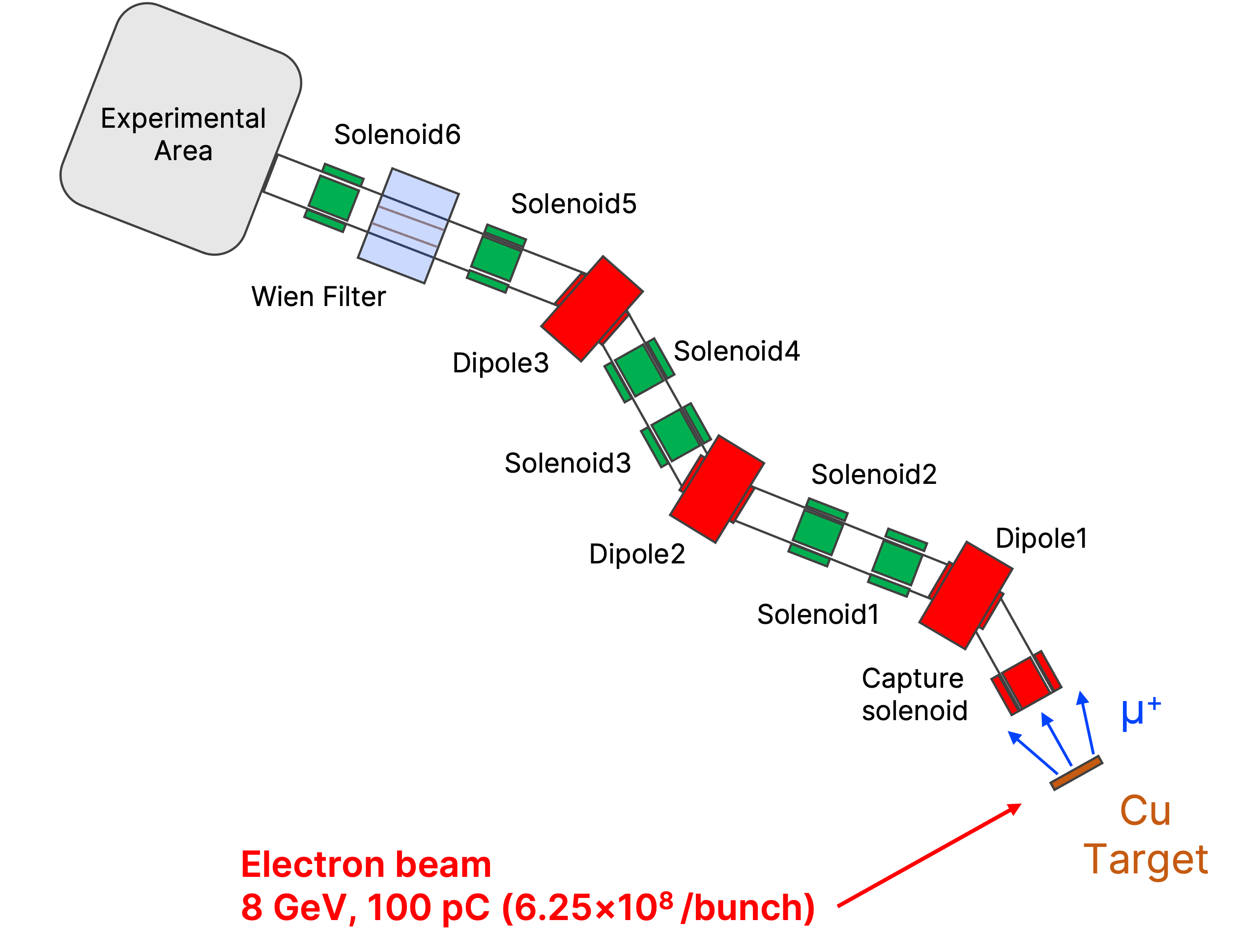
To simplify the design, three 640-mm rectangular bending dipoles of identical geometry were used for momentum selection and the elimination of negatively charged and neutral particles, instead of sector dipoles. This approach allows for adjustments to the bending angle by simply changing the magnetic field inside the dipole, without the need for redesign. A Wien filter is placed between the last two solenoids to filter out positrons further.
The optics parameters applied in the transport beamline to optimize the transmission of the surface muon beam are summarized in Tab. 3.
| Components | Position (m) | Length (mm) | Aperture (mm) | Field (T) |
|---|---|---|---|---|
| Capture solenoid | 0.47 | 373 | 500 | 0.432 |
| Dipole1 | 1.93 | 640 | 400 | -0.100 |
| Solenoid1 | 3.17 | 373 | 500 | 0.241 |
| Solenoid2 | 4.40 | 373 | 500 | 0.173 |
| Dipole2 | 6.05 | 640 | 400 | 0.100 |
| Solenoid3 | 7.17 | 373 | 500 | 0.136 |
| Solenoid4 | 8.00 | 373 | 500 | 0.199 |
| Dipole3 | 9.45 | 640 | 400 | -0.104 |
| Solenoid5 | 10.82 | 373 | 500 | 0.226 |
| Wien Filter | 11.75 | 1500 | 300 | |
| Solenoid6 | 13.18 | 373 | 500 | 0.440 |
| Exit | 13.58 |
III.5 Optimization of the beamline optics
To optimize the beamline optics, an algorithm integrating the pattern search method with the coordinate descent method was employed. The coordinate descent method optimizes a multivariate objective function by solving a series of univariate optimization problems sequentially. To facilitate the implementation, a cyclic approach was adopted, where each univariate problem is solved in turn, and once a complete cycle over all variables is finished, the process restarts with the first variable. Each univariate problem refines the solution estimate by optimizing selected variables while holding the others constant.
A pattern search method was chosen for solving the univariate optimization problems. This method relies solely on function evaluations and does not require the gradient of the function, making it particularly suitable for functions with hard-to-compute or unknown derivatives. Additionally, it is straightforward to implement. However, it is prone to converging to local maxima, and its effectiveness depends heavily on the initial value settings. Details of the implementation can be found in the Appendix.
III.6 Expected surface muon beam properties
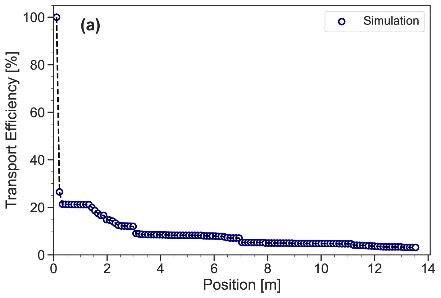
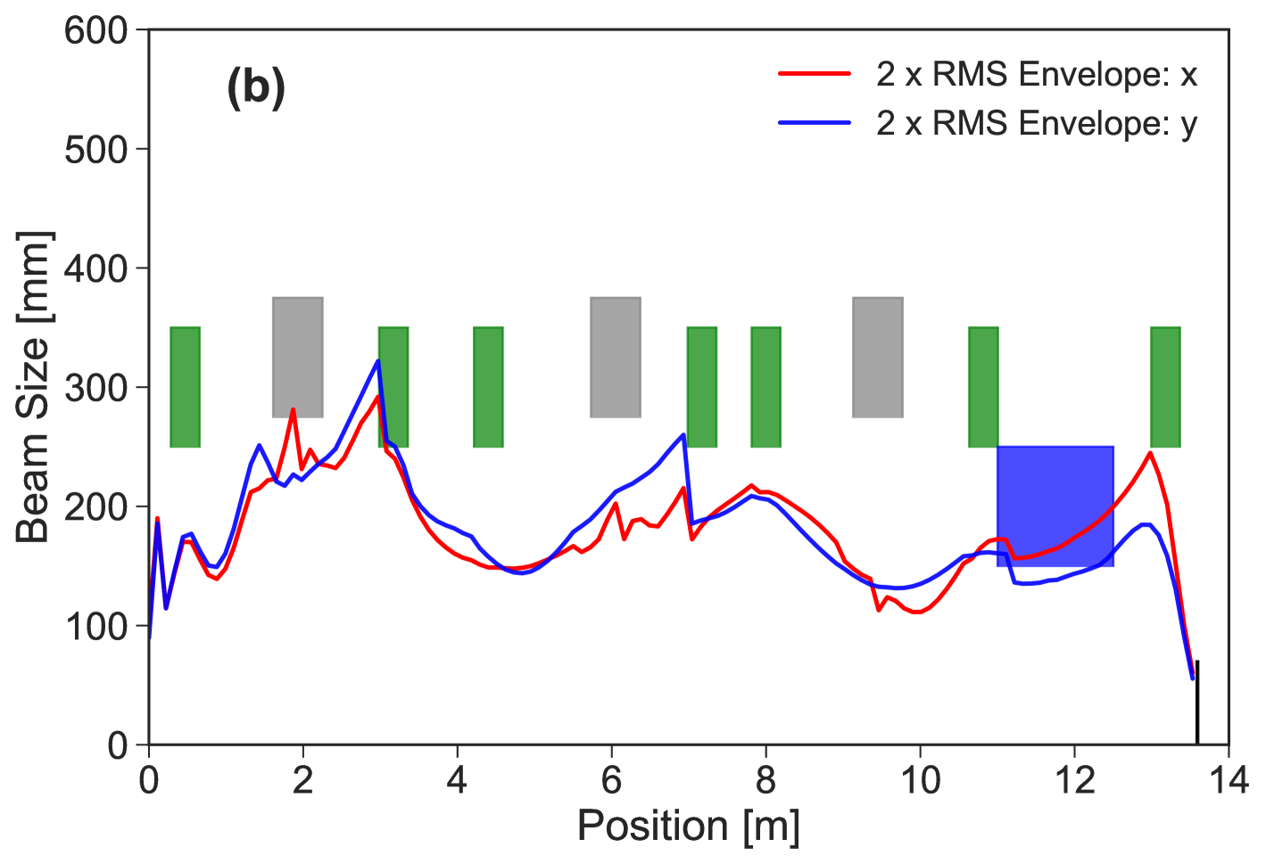
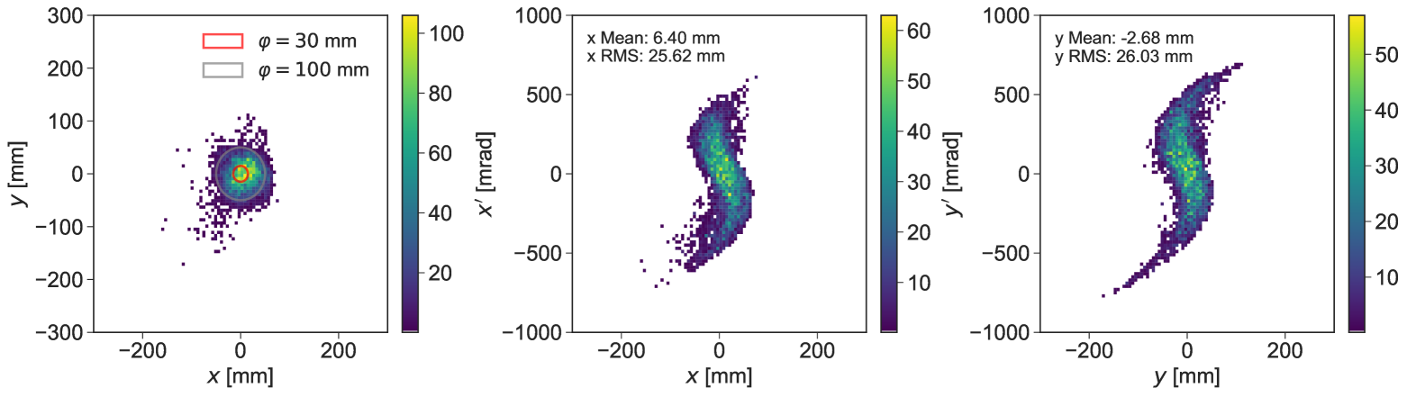
Figure 9 illustrates typical simulated results for the beam envelope and transport efficiency of surface muons along the beamline. The transport efficiency for surface muons from the target to the experimental area, with standard beam optics tuning, is 3.1% ± 0.03%. This efficiency includes a capture efficiency of approximately 21.2% ± 0.1% for surface muons in the capture solenoid and a transmission efficiency of about 14.8% 0.03% along the transport beamline. The anticipated surface muon intensity at the final focus is 60 /bunch or /s (for a repetition rate of 50 kHz), with an RMS beam size of 25.6 mm (horizontal) 26.0 mm (vertical), a momentum bite (p/p) of 3.69% and a polarization of 85%. The beam distribution and phase space at this beam location are illustrated in Fig. 10. Given that the sample size in a typical SR experiment is around 30 mm in diameter [28, 29], the distribution of surface muons within this range is particularly important. The muon intensity in this region is /s. The mean parameters of the surface muon beam spot are summarized in Tab. 4.
| Parameters | Value |
|---|---|
| x/x’ (RMS) | 25.6 mm / 221 mrad |
| y/y’ (RMS) | 26.0 mm / 246 mrad |
| p/p | 3.69% |
| Polarization | 85% |
| rate (All) | /s |
| rate (30 mm) | /s |
III.7 Positron removal schemes
In our target, approximately positrons per bunch are generated. Some of these may contaminate the experimental area. Since positrons serve as the signal in SR experiments, this presents a major background issue. To reduce positron contamination, we implemented a system that combines multiple bending magnets with a Wien filter. Parameters such as voltage and plate gap were chosen to be reasonable values with reference to existing facility [30], and plate length was determined considering the available length. The main parameters of the Wien filter are provided in Table. 5.
| Parameter | Value |
|---|---|
| Electric field () | -2.67 MV/m |
| Magnetic field () | 0.0328 T |
| Length () | 1500 mm |
| Plate Gap () | 300 mm |
Using a simulation with electrons-on-target, we detected 62 positrons at the 30 mm beam spot following their transportation through the beamline that has been optimized for the surface muon. Scaling this result to SHINE’s design electron bunch charge ( electrons), we projected that approximately 3,880 positrons would reach the beam spot per bunch while only around 10 muons can be transported. This calculation assumes linear scaling. Although this positron-to-muon ratio significantly decreases from the initial near the target, it still presents a major challenge for SR experiments, which usually require positron contamination to be below 1%.
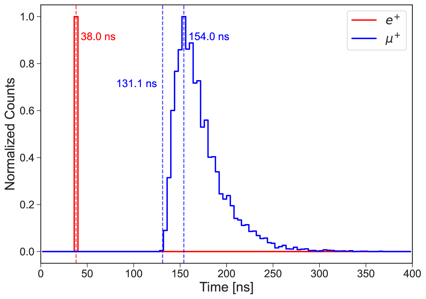
Therefore, in addition to the Wien filter, we are exploring an alternative approach using a fast kicker with strip lines and a septum magnet to eliminate positrons from the beamline. The positron background in the beamline has the same momentum as the muon but experiences a different time of flight due to its varying mass. This difference could be utilized to remove positrons. As shown in Fig. 11, the time-of-flight difference between positrons and muons at 11 m from the target in this beamline is approximately 100 ns.
Advanced XFEL facilities utilize fast kicker systems to distribute high-energy electron beams across multiple beamlines at MHz-level repetition rates. For example, at SHINE, a lumped inductance kicker is currently being developed utilizing a vacuum chamber equipped with a single-turn coil [31]. This kicker is capable of operating at a frequency of 1 MHz, possesses a magnetic pulse width of 600 ns, and achieves a full magnetic strength of 0.005 T; at DESY’s European XFEL, 20 GeV electron beams operate at 4.5 MHz, with excess electrons not used for lasing being dumped by fast kickers that have maximum pulse widths of 30 ns and rise/fall times of 15 ns [32]. By designing a similar fast kicker system specifically for muon beamlines, we believe the positron contamination issue can be effectively resolved. This promising approach, along with design optimization studies and comprehensive performance analysis, should be thoroughly explored in an upcoming publication dedicated to positron removal for muon experiments.
IV Conclusions
This article introduced the concept of a muon source utilizing a high-repetition-rate electron beam and a transport beamline design. A muon beam with a repetition rate of approximately 50 kHz, optimal for typical muon experiments, can be generated. Compared to current proton-driven muon sources, the relatively low muon production rate is compensated by the high repetition rate, resulting in a muon yield comparable to existing sources.
Using a straightforward beamline configuration consisting of solenoids, bending magnets, and a Wien filter, the surface muon intensity delivered to the experimental area was estimated to be approximately /s for a beam spot 30 mm. The realization of this concept requires further detailed design studies, including optimization of target geometry, thermo-mechanical calculations for the target, and proof-of-principle experiments. The removal of positrons is particularly challenging. Once constructed, this high-repetition-rate pulsed muon beamline is well-suited for applications in SR spectrometer [33], muon electric dipole moment (EDM) searches [34, 35], and muonium-to-antimuonium conversion experiments [36, 37, 38]. Additionally, its unique timing structure complements the Chinese Muon Facilities currently under construction at the Chinese Spallation Neutron Source (CSNS) [39] in Dongguan, Guangdong, China, and is being studied with the Initiative Accelerator Driven Subcritical System (CiADS) [40] and the High-Intensity Heavy-Ion Accelerator Facility (HIAF) [41] in Huizhou, Guangdong, China.
Acknowledgements.
We are extremely grateful to Yu Bao, Vadim Grinenko, Hong Ding, Bo Liu, Zhi Liu, Jian Tang, Dao Xiang, and Zhentang Zhao for fruitful discussions regarding the beamline optimization and physics potential of the SHINE muon beam. F. Liu, S. Chen, and L. Wang were supported by the Participation in Research Program (PRP) of Shanghai Jiao Tong University (Program number T426PRP43001). The work of M. Lyu, Y. Takeuchi, J. Wang, and K. S. Khaw was supported by the Shanghai Pilot Program for Basic Research (Grant number 21TQ1400221).Appendix 1: Muon Yield Comparison between g4beamline and FLUKA
Figure 12 shows a comparison of positive muon yield between g4beamline and FLUKA. No significant differences are observed in the yield for momentum regions below 300 MeV/c, showing generally good agreement between the two calculation codes. However, there are some discrepancies in behavior near the two peaks. In the momentum region of 25-30 MeV/c, the yields differ by up to approximately 30%. The accuracy of these simulation models needs to be quantitatively evaluated through future experimental validation.
Appendix 2: Pattern search algorithm for the beamline optimization
This algorithm ensures a balanced search throughout the variables in a multi-dimensional optimization problem. An example of the procedure for the algorithm is described below. In this example, we consider maximizing the value of the multivariate function , where , and is the number of variables.
-
1.
Initialization:
-
•
Set the initial search points and initial step sizes .
-
•
-
2.
Iteration:
-
•
For each variable and step size , proceed with the following steps.
-
•
Evaluate the function at three points , , .
-
•
Select the point with the highest function value and update the search point to this point if it is different from the current search point.
-
•
Then, adjust the step size ; maintain if there was an update of the search point, halves it if not.
-
•
-
3.
Update:
-
•
After completing a cycle of searches across all variables, return to the first variable and repeat the search process from the updated search point .
-
•
-
4.
Termination:
-
•
Terminate the algorithm if the step size falls below a pre-defined threshold.
-
•
Here, the objective function was the number of surface muons transported to the experimental area, the variables were the position and field strength of each optics component. To avoid local maxima as much as possible, simulations were initially performed using several randomly generated beamline configurations, and the configuration with the highest number of surface muon transported was used as the initial search point.
References
- Gorringe and Hertzog [2015] T. P. Gorringe and D. W. Hertzog, Precision Muon Physics, Prog. Part. Nucl. Phys. 84, 73 (2015), arXiv:1506.01465 [hep-ex] .
- Hillier et al. [2022] A. D. Hillier, S. J. Blundell, I. McKenzie, I. Umegaki, L. Shu, J. A. Wright, T. Prokscha, F. Bert, K. Shimomura, A. Berlie, H. Alberto, and I. Watanabe, Muon spin spectroscopy, Nature Reviews Methods Primers 2, 4 (2022).
- Cywinski et al. [2009] R. Cywinski et al., Towards a dedicated high-intensity muon facility, Physica B 404, 1024 (2009).
- Adelmann et al. [2010] A. Adelmann, K. Kirch, C. J. G. Onderwater, and T. Schietinger, Compact storage ring to search for the muon electric dipole moment, J. Phys. G 37, 085001 (2010).
- Willmann and Jungmann [2021] L. Willmann and K. Jungmann, Muonium-Antimuonium Conversion, SciPost Phys. Proc. 5, 009 (2021).
- Kanda [2022] S. Kanda, Toward a high-precision measurement of the muon lifetime with an intense pulsed muon beam at J-PARC, PoS NuFact2021, 215 (2022).
- Ema et al. [2023] Y. Ema, T. Gao, and M. Pospelov, Muon spin force (2023), arXiv:2308.01356 [hep-ph] .
- Kuno [2000] Y. Kuno, Physics opportunities of a very intense low-momentum muon source, Nucl. Instrum. Meth. A 451, 233 (2000).
- Seidel [2021] M. Seidel, Cyclotrons and Fixed Field Alternating Gradient Accelerators (2021) arXiv:2105.04477 [physics.acc-ph] .
- Liu et al. [2020] Y. Liu, A. Rakhman, C. D. Long, Y. Liu, and T. J. Williams, Laser-assisted high-energy proton pulse extraction for feasibility study of co-located muon source at the SNS, Nucl. Instrum. Meth. A 962, 163706 (2020), arXiv:2004.03517 [physics.acc-ph] .
- Bartoszek et al. [2014] L. Bartoszek et al. (Mu2e), Mu2e Technical Design Report (2014), arXiv:1501.05241 [physics.ins-det] .
- Nagamine et al. [2009] K. Nagamine, H. Miyadera, A. Jason, and R. Seki, Compact muon source with electron accelerator for a mobile mu SR facility, Physica B 404, 1020 (2009).
- Titov et al. [2009] A. I. Titov, B. Kampfer, and H. Takabe, Dimuon production by laser-wakefield accelerated electrons, Phys. Rev. ST Accel. Beams 12, 111301 (2009), arXiv:0907.3038 [physics.acc-ph] .
- Dreesen et al. [2014] W. Dreesen, J. A. Green, M. Browder, J. Wood, D. Schwellenbach, T. Ditmire, G. Tiwari, and C. Wagner, Detection of petawatt laser-induced muon source for rapid high-z material detection, in 2014 IEEE Nuclear Science Symposium and Medical Imaging Conference (NSS/MIC) (2014) pp. 1–6.
- Rao et al. [2018] B. S. Rao, J. H. Jeon, H. T. Kim, and C. H. Nam, Bright muon source driven by GeV electron beams from a compact laser wakefield accelerator, Plasma Phys. Control. Fusion 60, 095002 (2018), arXiv:1804.03886 [physics.plasm-ph] .
- Zhao et al. [2018] Z. Zhao, D. Wang, Z.-H. Yang, and L. Yin, SCLF: An 8-GeV CW SCRF Linac-Based X-Ray FEL Facility in Shanghai, in 38th International Free-Electron Laser Conference (2018) p. MOP055.
- Liu et al. [2024] T. Liu, S. Chen, H. Deng, Z. Gao, N. Huang, B. Liu, and Z. Qi, Layout of the Undulator-to-dump line at the SHINE, JACoW FLS2023, WE4P14 (2024).
- Lv et al. [2023] M. Lv, J. Wang, and K. S. Khaw, A pulsed muon source based on a high-repetition-rate electron accelerator, JACoW IPAC2023, TUPA087 (2023).
- Berg et al. [2016] F. Berg et al., Target Studies for Surface Muon Production, Phys. Rev. Accel. Beams 19, 024701 (2016), arXiv:1511.01288 [physics.ins-det] .
- Chen et al. [2023] C. Chen, Y. Bao, and N. Vassilopoulos, Design of the surface muon beamline of MELODY, J. Phys. Conf. Ser. 2462, 012027 (2023).
- Ferrari et al. [2005] A. Ferrari, P. R. Sala, A. Fasso, and J. Ranft, FLUKA: A multi-particle transport code (Program version 2005) (2005).
- Note [1] The the typical electron beam spot from the SHINE superconducting linac is about (10 ). However, at this small beam size, it will produce excessively high power density. At a repetition rate of 50 kHz, the copper target may not endure the thermal load. The 2 mm beam spot assumed here is based on a recent SHINE beam dump study [42], and this number will be optimized with a more focused study based on the target’s thermal engineering design. To achieve a millimeter-sized beam spot, a beam spoiler system can be utilized. Such a spoiler system is commonly employed at the end of the SLAC linac to degrade the beam at the A-line and ESA [43].
- Roberts and Kaplan [2007] T. J. Roberts and D. M. Kaplan, G4Beamline Simulation Program for Matter dominated Beamlines, Conf. Proc. C 070625, 3468 (2007).
- Khasanov [2022] R. Khasanov, Perspective on muon-spin rotation/relaxation under hydrostatic pressure, J. Appl. Phys. 132, 190903 (2022), arXiv:2208.11320 [physics.ins-det] .
- Tuomisto and Makkonen [2013] F. Tuomisto and I. Makkonen, Defect identification in semiconductors with positron annihilation: Experiment and theory, Rev. Mod. Phys. 85, 1583 (2013).
- Selim [2021] F. Selim, Positron annihilation spectroscopy of defects in nuclear and irradiated materials- a review, Materials Characterization 174, 110952 (2021).
- Maso et al. [2023] G. D. Maso et al., Future facilities at PSI, the High-Intensity Muon Beams (HIMB) project, EPJ Web Conf. 282, 01012 (2023).
- Pak et al. [2021] K. Pak, J. Park, J. Y. Jeong, J. C. Kim, K. Kim, Y. H. Kim, J. Son, J. H. Lee, W. Lee, and Y. K. Kim, Beam line design and beam transport calculation for the sr facility at raon, Nuclear Engineering and Technology 53, 3344 (2021).
- Zhou et al. [2022] L.-P. Zhou, X.-J. Ni, Z. Salman, A. Suter, J.-Y. Tang, V. Vrankovic, and T. Prokscha, Simulation studies for upgrading a high-intensity surface muon beamline at paul scherrer institute, Phys. Rev. Accel. Beams 25, 051601 (2022).
- Ikedo et al. [2013] Y. Ikedo, Y. Miyake, K. Shimomura, P. Strasser, N. Kawamura, K. Nishiyama, S. Makimura, H. Fujimori, A. Koda, J. Nakamura, T. Nagatomo, Y. Kobayashi, T. Adachi, A. Pant, T. Ogitsu, T. Nakamoto, K. Sasaki, H. Ohata, R. Okada, A. Yamamoto, Y. Makida, M. Yoshida, T. Okamura, R. Okubo, W. Higemoto, T. Ito, K. Nakahara, and K. Ishida, Positron separators in superomega muon beamline at j-parc, Nuclear Instruments and Methods in Physics Research Section B: Beam Interactions with Materials and Atoms 317, 365 (2013), xVIth International Conference on ElectroMagnetic Isotope Separators and Techniques Related to their Applications, December 2–7, 2012 at Matsue, Japan.
- Liu [2024] Development of a high-repetition-rate lumped-inductance kicker magnet prototype for the beam switchyard of shine, Nuclear Science and Techniques 35, 37 (2024).
- Obier et al. [2019] F. Obier et al., Fast Kicker System for European XFEL Beam Distribution, in 39th International Free-Electron Laser Conference (2019) p. WEP013.
- Li et al. [2023] Q. Li, Z. Pan, Y. Bao, T. Yang, H. Cheng, Y. Li, H. Hu, H. Liang, and B. Ye, Design of the First SR Spectrometer at China Spallation Neutron Source, J. Phys. Conf. Ser. 2462, 012022 (2023).
- Adelmann et al. [2021] A. Adelmann et al., Search for a muon EDM using the frozen-spin technique (2021), arXiv:2102.08838 [hep-ex] .
- Adelmann et al. [2025] A. Adelmann et al., A compact frozen-spin trap for the search for the electric dipole moment of the muon, (2025), arXiv:2501.18979 [hep-ex] .
- Han et al. [2021] C. Han, D. Huang, J. Tang, and Y. Zhang, Probing the doubly charged Higgs boson with a muonium to antimuonium conversion experiment, Phys. Rev. D 103, 055023 (2021), arXiv:2102.00758 [hep-ph] .
- Bai et al. [2022] A.-Y. Bai et al., Snowmass2021 Whitepaper: Muonium to antimuonium conversion, in Snowmass 2021 (2022) arXiv:2203.11406 [hep-ph] .
- Bai et al. [2024] A.-Y. Bai et al., Conceptual Design of the Muonium-to-Antimuonium Conversion Experiment (MACE), (2024), arXiv:2410.18817 [hep-ex] .
- Bao et al. [2023] Y. Bao et al., Progress report on Muon Source Project at CSNS, J. Phys. Conf. Ser. 2462, 012034 (2023).
- Cai et al. [2024] H.-J. Cai et al., Towards a high-intensity muon source, Phys. Rev. Accel. Beams 27, 023403 (2024), arXiv:2309.01520 [physics.acc-ph] .
- Xu et al. [2025] Y. Xu et al., The Feasibility Study of the GeV-Energy Muon Source Based on HIAF, (2025), arXiv:2502.20915 [physics.acc-ph] .
- Yuhai et al. [2020] X. Yuhai, W. Guanghong, L. Zhefu, X. Wenzhen, Z. Bintuan, L. Jiongjun, Y. Fubin, and X. Xiaobin, Design of beam dump for the commissioning at shine facility, Radiation Protection 40, 510 (2020).
- Nosochkov et al. [2019] Y. Nosochkov, C. Hast, T. Markiewicz, L. Nicolas, T. Raubenheimer, and M. Santana-Leitner, Simulations of Beam Shaping for Dark Matter Experiments at LCLS-II, in 10th International Particle Accelerator Conference (2019) p. WEPMP049.