XR-penter: Material-Aware and In Situ Design of Scrap Wood Assemblies
Abstract.
Woodworkers have to navigate multiple considerations when planning a project, including available resources, skill-level, and intended effort. Do it yourself (DIY) woodworkers face these challenges most acutely because of tight material constraints and a desire for custom designs tailored to specific spaces. To address these needs, we present XR-penter, an extended reality (XR) application that supports in situ, material-aware woodworking for casual makers. Our system enables users to design virtual scrap wood assemblies directly in their workspace, encouraging sustainable practices through the use of discarded materials. Users register physical material as virtual twins, manipulate these twins into an assembly in XR, and preview cuts needed for fabrication. We conducted a case study and feedback sessions to demonstrate how XR-penter supports improvisational workflows in practice, the type of woodworker who would benefit most from our system, and insights on integrating similar spatial and material considerations into future work.
(a) – (b) — (c)—
1. Introduction
Carpentry is an ancient craft that has evolved through centuries, integrating various technologies to enhance precision and creativity. Recently, digital fabrication has further expanded this field, enabling complex designs (Zoran et al., 2013), efficient material usage (Zhao et al., 2022; Wu et al., 2019), and automation (Lipton et al., 2018). Despite these advancements, the needs of manual woodworkers, who either work with limited materials and/or want to design a custom assembly that fits into their environment, are not as widely addressed in human–computer interaction (HCI) research. Although several works offer alternatives to handcraft (Larsson et al., 2020; Tian et al., 2018; Saul et al., 2010; Baudisch et al., 2019; Sethapakdi et al., 2021; Bourgault et al., 2023), we aim to contribute to the body of work that complements existing manual workflows (Leen et al., 2019; Toka et al., 2023; Schoop et al., 2016; Tian and Paulos, 2021). For woodworkers, a primary challenge is planning a design that can balance competing considerations such as available material, space, tools and abilities. Do it yourself (DIY) woodworkers, who we define as non-professionals with limited access to materials and/or tools, experience this challenge extensively because of added fabrication constraints (Bezci, 2016).
Therefore, an effective computational support system for manual woodworking should encode wood-specific design methods and material considerations. Nordmoen et al.’s observations in wood workshops highlight a material-first approach (Nordmoen and McPherson, 2022). For example, one shop took extra care to conserve timber, utilizing material that would otherwise be considered flawed for furniture creation and discarded. Physical interactions with the material are important, as they set woodworking apart as a craft, rather than a purely industrial practice (Bunn, 1999; Hoadley, 2000). To avoid using expensive material or inaccessible tools, DIY woodworkers must adopt unique design principles such as employing basic craft techniques and utilizing on-hand materials (Camburn and Wood, 2018). More specifically, DIYers frequently use discarded wood (scrap) (Bonvoisin et al., 2017). They may already have access to a collection of wood off-cuts from past projects, or may gather scraps (often for free) from construction yards, maker-spaces, or online listings.
Although acquiring this material is easy, planning a design around it is challenging. Scraps are random in terms of their size, appearance, and quality. This requires woodworkers to adopt a bricolage approach – adapting their designs to fit materials on hand, as explored in previous HCI fabrication research (Efrat et al., 2016; Beltagui et al., 2021; Stemasov et al., 2022). When successful, this approach is not only affordable, but aligns with sustainable practices, recycling material that would otherwise be wasted (Besserer et al., 2021). Several previous works focus on various types of scrap materials, including leather (Lin and Jo, 2024), plastic bags (Deshpande et al., 2022), e-waste (Lu et al., 2023), 3D-printed filament (Wall et al., 2021; Dew and Rosner, 2019), and household waste (Wall et al., 2023). We aim to contribute to this field with a creative design interface for discarded wood. Screen-based desktop computer-aided design (CAD) interfaces are not optimized for material-informed design because they are abstracted from the real world (Menges, 2012). We see an opportunity for an extended reality (XR) interface to connect physical materials to a virtual design in the same space, bringing material awareness into digital design. XR is also suitable for in situ design, allowing the woodworker to verify that a design is functionally and aesthetically compatible with their surroundings.
Therefore, we present XR-penter, a system designed to support functional woodworking with discarded material (Fig. 1). XR-penter is designed for makers who would rather adapt their project to available scraps rather than purchase new materials for a fixed design. Our system leverages the capabilities of a commercially available headset to create an XR experience that integrates into manual workflows. XR-penter’s backbone is a digital inventory of scrap wood containing a virtual twin of each available scrap. Users interactively cut and join the pieces from this inventory into a virtual assembly. Specialized modeling utilities facilitate physically valid cuts, part placement, simple connections and snapping to the surrounding environment. While the user designs their assembly in XR, the system generates a 2D cut plan for each twin. The system also provides real time feedback on material availability, such as informing the user when they attempt to extend the length of a cut piece beyond the dimensions of their material. This enables creative negotiation between material and design informed by environmental fixtures. Once the user finishes their design, they can view it on a screen-based interface with necessary information for fabrication. We demonstrate the feasibility of our system in collaboration with a DIY woodworker, where we design and build furniture using random scraps. We also share feedback from eight hobbyist woodworkers to determine how XR-penter could integrate into their design process.
Our contributions include:
-
•
A study of the requirements for DIY woodworking through formative interviews with six DIY woodworkers.
-
•
An XR system for in situ visualization and design of functional assemblies built with on-hand materials, including a virtual inventory of 3D scraps, woodwork-specific modeling utilities, and user-controlled cut plan generation.
-
•
A case study and feedback sessions with target users demonstrating how XR-penter supports the improvisational nature of woodworking with scraps.
2. Related Work
2.1. Interactive Design for Woodwork
There are several computational approaches that either augmented or replaced traditional CAD tools to facilitate the design of wood structures, with scopes ranging from joint-specific design (Larsson et al., 2020; Yao et al., 2017; Magrisso et al., 2018) to general wood assemblies (Lau et al., 2011; Schulz et al., 2014; Shao et al., 2016). For example, Carpentry Compiler provides real-time feedback on manufacturability for wood furniture designed with CAD, optimizing the plan after the design is finalized (Wu et al., 2019). MatchSticks supports improvisational fabrication with a CNC machine (Tian et al., 2018). These design interfaces focus on fabrication constraints. Other studies reported woodworking interfaces incorporating validity (Saul et al., 2010; Umetani et al., 2012) and reproducible workflows (Tran O’Leary et al., 2024). We share a common goal with these works in making digital design less abstract through constraints; however, our work specifically addresses design with limited non-standard materials. Further, some design interfaces are aimed at hobbyists who want to avoid complex CAD interfaces, who are also are target users. For example, CraftyAmigo111CraftyAmigo https://www.craftyamigo.com allows users to snap together pre-defined wood parts to design furniture and provides a shopping list of necessary stock material. SketchUp222SketchUp https://www.sketchup.com/en/products/sketchup-for-web is another easy-to-use tool that allows a user to generate a cut list after creating a virtual model. However, the pattern generation is separated from the design process and is assumed to work with perfect stock. As desktop applications, these tools are inherently disjointed from physical material and surroundings. In contrast, our system enables situated design, allowing users to make material-informed design choices in situ.
2.2. Designing with Material Constraints
In CAD workflows, a material is typically treated as “a passive property of form, rather than as an active form-generator,” which means that the material is assigned to the completed design instead of being embedded into the design process (Menges, 2012). There is a growing body of HCI research that addresses this gap between material and digital design. Previous material-first design methods have targeted a variety of materials such as clay (Bourgault et al., 2023), stone (Johns et al., 2023), and organic tree branches (Mollica, Zachary and Self, Martin, 2016). Material constraints may also augment design for rectilinear material, such as laser-cut assemblies (Baudisch et al., 2019; Dogan et al., 2021). Fabricaide, a pattern generation system for laser-cutting, shares our goal of providing real-time feedback on material availability while the user designs their project (Sethapakdi et al., 2021). For manual woodworking, some works packed parts onto user-defined stock by optimizing for material cost and time (Leen et al., 2019; Wu et al., 2019; Zhao et al., 2022). Although auto-packing approaches are efficient, they necessitate perfect materials and limit opportunities for creative design around material properties. Koo et al. took a unique approach by suggesting modifications to the 3D furniture design for minimizing waste as they auto-packed the pattern (Koo et al., 2017). Instead of algorithmic optimization, we generate patterns interactively similarly to PacCAM, which uses 2D rigid bodies and snapping for easy arrangement (Saakes et al., 2013). This user-controlled packing approach material informed design decisions beyond surface conservation. Since we focus on rectilinear wood, we also forgo the need to create 3D scans, which have been utilized in other works (Cousin et al., 2023; Larsson et al., 2019; Sunshine, 2022).
2.3. Designing In Situ
In situ interfaces introduce spatial awareness and context-specific data into the design process, which are otherwise lost in screen-based software. Existing systems have brought situated design to a variety of fields, including plastering (Mitterberger et al., 2022), circuits (Kim et al., 2019) and ergonomic desks (Lee et al., 2018). To assist furniture design, Protopiper enables users to physically prototype large-scale objects through plastic tube extrusion (Agrawal et al., 2015). Lau et al. provided a method to design “complementary” household objects using a photo reference (Lau et al., 2010). Other works turned existing objects into design tools, such as physical “stamps” (Lau et al., 2012), traced shapes (Reipschläger and Dachselt, 2019), or scanned meshes (Weichel et al., 2014). Similarly, we provide design guidance using to-scale objects; however, instead of physical material, users assemble with virtual “twins.” Stemasov et al. utilized XR to preview design alterations to existing artifacts (Stemasov et al., 2020, 2023). Their work, pARam, provides a real-time AR preview of adjustments made to existing parametric design models (Stemasov et al., 2024). Although easy to use, suitable parametric models can be difficult to source, so we enable users to create custom designs directly in XR via woodworking-specific modeling utilities. Finally, we acknowledge that real world measurements are crucial for creating designs that fit in space and accommodate available material (Ramakers et al., 2023). SPATA’s physical tools measure real-world objects and encode the data into CAD software (Weichel et al., 2015). Instead of specialized hardware, we use existing dimensions of uncut material and spatial data obtained using our XR headset to determine the final measurements for assembly.
2.4. XR for Physical Fabrication and Design
There is a growing body of fabrication-focused XR systems that augment interactions with real objects and/or materials (Dogan et al., 2022). ToolDevice, one of the earliest examples of XR handcrafting, enabled users to build virtual wood models using physical tools (Arisandi et al., 2014). Knock on Wood also explored tool-based virtual interactions in XR (Strandholt et al., 2020). Yanpanyon et al. demonstrated that XR improves spatial reasoning for DIY furniture assembly (Yanpanyanon et al., 2020). The architectural startup Fologram333Fologram https://fologram.com/ provided an XR framework for architectural-scale fabrication. Cousin et al. used Fologram to construct structures with nonstandard wood branches (Cousin et al., 2023), while Jahn et. al used the system to fabricate structures with reclaimed timber offcuts (Jahn et al., 2024). Further, Parry et. al utilized Fologram to reuse scrap timber, using a holographic overlay to cut nested parts and assemble them into a structure (Parry and Guy, 2021). These Fologram-based works demonstrate that XR is capable of supporting physical assembly. They focused on XR as a fabrication guide, and designs were generated with computational models in advance. Most adjacent to our work, Kyaw et al. utilized Fologram for parametric exploration of bamboo’s bending properties in situ (Kyaw, 2023). In contrast, our system supports creative scrap wood design for personal assemblies.
3. Formative Interviews
In this section, we detail our findings from a series of formative interviews focused on the needs and challenges of DIY woodworkers. Due to their lack of professional training, we assume they are more likely to underestimate material requirements and not understand how their design will function in a given space. We also assume that DIYers are more likely to use scrap material and basic tools. We interviewed six non-professional woodworkers (P1-P6), between ages 22 to 71, to evaluate these assumptions and enrich our practical understanding of how they execute projects. Participants were unpaid volunteers recruited from the local maker community. P4, P5, and P6 prefer to use scrap material for their DIY projects, while the other participants use scraps on a per-project basis. P3 and P5 rely on CAD to create woodworking plans, while the rest of the participants work with paper. We conducted semi-structured interviews that lasted approximately 1 hour. The first 45 minutes were spent on design approaches, tools and material. The last 15 minutes were dedicated to discussing spatial computing use cases for woodworking, and those unfamiliar with XR were shown examples of 3D objects in a mixed-reality environment. We took a bottom-up approach in our thematic analysis of interview responses to identify three main challenges: managing material needs (Section 3.1), negotiating between material and design (Section 3.2), and spatial visualization (Section 3.3).
3.1. Managing Material Needs
All interviewees reported struggling with either the high cost of quality timber or limitations of available scrap materials. P1, who was the president of her university’s makerspace, noted a reliance on scrap wood due to financial constraints. The makerspace treats scrap wood as a shared resource, typically adequate for low-cost, functional designs. P1 also observed that students working with scraps often use hand and power tools, reserving digital fabrication tools for more precise and expensive projects. P5 mentioned that it takes time to determine the suitability of discarded material, requiring him to touch and closely examine every scrap to ”fully understand” it. Five out of six interviewees reported that they have had to manually adjust a design after starting to cut and assemble it because they inaccurately predicted their material requirements. P2 stated, “I always underestimate how much lumber I need… [wood] is not infinite.” P4 explained that he always has “90% of the material [physically with him] straight away” before designing his assembly to be certain about not falling short.
3.2. Negotiating Between Material and Design
We observe two approaches to mapping a design to available materials from our interviews: 1) a material-first approach that involves creating a design to accommodate material that has been allocated for a project, and 2) a design-first approach that involves searching for material to accommodate an existing plan. In practice, these approaches often overlap. For example, P1 was building a bathroom shelf and initially planned for three shelves. After realizing she had more material than expected, she added two extra shelves. Such improvisational decisions, while successful in P1’s case, are not always feasible mid-assembly. To create a cut list, which details the dimensions and quantities of pieces needed for a project, P2 sketches out necessary pieces and mentally “extrapolates from the sketch,” while P5 manually inputs measurements into CAD and creates a digital model, before disassembling it into a 2D pattern, printing it out, and tracing cuts onto available wood.
Although there are online cut-list optimizers, P6 explained that these tools are incompatible with his typical workflow because it is “rare that [he] has a lot of stock material,” on hand, and that it he is also “unsure if [he] can specify the parts he needs in advance [of the design]”. As woodworkers organize their cut lists, they often dynamically edit their design; P6 likens this process to “sketching.” Conserving surface area is not the only goal throughout this process: the physical logistics of fabricating cuts must also be considered. P1 creates patterns to avoid repeatedly re-calibrating her table saw, while P3 and P6 determine how precise their patterns are based on the tools at their disposal and their self-perceived skill levels. Further, they juggle other material properties as they design: P1 said she would appreciate a tool that allowed her to design around imperfections, thereby creating less waste.
3.3. Spatial Visualization
Spatially visualizing an assembly while it is being designed is a bottleneck voiced by all interviewees. P5 relies on design software but picks up wood scraps and “physically rotates them in mid air” to understand how they occupy space before switching to designing on his computer. All interviewees acknowledged that spatial computing could enhance this process. P2, for instance, designed planters on paper but realized post-assembly that they “visually dominated” his backyard. He suggested that if he owned an XR headset, he could have used it to visualize and adjust his plans. P4, a cafe owner who built a new counter-top with reclaimed wood, found that the final layout made accessing his fridge difficult. Previewing his design in situ would have enabled him to practice moving around different configurations and adjusting the design accordingly, instead of realizing its limitations post-assembly.
3.4. Takeaways
DIY woodworkers must estimate and manage material requirements over the entire life cycle of a project. Even when all materials are already available on-hand, predicting if it is sufficient for their intended project remains difficult. They must also determine if available material meets structural and aesthetic standards. This is complicated by the need to balance multiple material considerations at once, especially when irregular scraps are involved. Translating a design to physical materials requires mental extrapolation, and going back and forth between design creation and material allocation requires intensive context-switching. Further, we observe that it is difficult to explore the material-constrained design space without making irreversible cuts. Woodworkers find it difficult to visualize how a design will occupy space within its environment, whether it be in terms of physical dimensions, layout, or functionality. Woodworkers who use CAD (as opposed to sketching) could achieve a more precise spatial understanding of their design; however, re-contextualizing a digital model for the physical material and space is tedious. In general, a lack of situated spatial visualization leads to post-assembly adjustments, wasted material, or dissatisfaction with the built object. Finally, P1 also shared that her university’s maker-space just opened a new XR division where students can borrow headsets. This is in line with our vision of XR becoming a practical and accessible addition to DIY craft.
4. XR-penter
4.1. Overview
Based on the challenges identified by our formative interviews, we propose an XR system that connects three woodworking design contexts: 1) the physical material (Fig. 2a), 2) in situ spatial model (Fig. 2b), and 3) cut plan (Fig. 2c). Together, these contexts help a woodworker engage in an iterative feedback loop towards a design informed by real constraints. Unlike traditional workflows, XR-penter tracks all three contexts simultaneously, supporting on-the-fly design decisions as new material constraints and spatial considerations emerge.
(a) – (b) — (c)—
The XR-penter workflow is divided into three phases: material registration, design, and fabrication. The design phase, which involves spatial modeling and cut-plan generation, occurs in XR. Material registration and fabrication occur out of the headset, aided by our screen-based interface. The system supports back-and-forth transitions between the material registration and design phases; however it assumes that design intent is finalized before physical fabrication.
4.2. Material Registration
The first step is to register available materials into XR-penter’s virtual inventory using a screen-based interface such as a desktop or laptop computer (Fig. 3). The inventory may persist across design sessions, and scraps can be re-registered on the screen-based interface during any point of the design process; however, we assume that the user will start with some registered material. To register a scrap, the user manually measures its dimensions and types the values into our interface. They may add an optional tag to note intended usage, imperfections, or other relevant features. Further, the user can assign a material type, associated with a predefined set of parameters driving the system’s procedural wood shader. The user may choose to edit grain axis, size, wobble and color to better match the scrap. Once a scrap is registered, its thumbnail appears in the inventory, along with its tag, material type, and dimensions. Each virtual scrap is assigned a number, and the user will mark the same number on the physical scrap to link the two.
(a) – (b) — (c)—
4.3. Spatial Model
Each inventory entry references a virtual twin of the physical scrap, and become accessible once the user wears their headset. The user assembles these twins into a spatial model with the assistance of woodworking-relevant modeling utilities. Certain utilities described below are accessed via canvas menus (Fig. 4f).
Cutting Parts
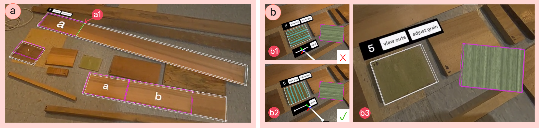
To add a scrap to their design environment, the user opens the virtual inventory menu in XR and selects its thumbnail, causing a 3D to-scale virtual twin to appear in front of them. The user can then subtract material from the twin by directly manipulating faces and edges, thereby cutting a part. Faces are selected with a ray interactor (a pointer that extends out from a controller to a selection surface), and can be pushed or pulled along their normal vector (Fig. 4a). Edges are selected with a poke interactor (a point on the controller that directly touches a selection surface), and can be moved along one of two perpendicular axes (Fig. 4b). If the user attempts to return an edge back to , it will snap into place within a small tolerance of being square.
(a) – (b) — (c)—
The user either duplicates an existing part or selects the twin’s 2D cut plan to cut new parts out of a twin. These parts can be resized, duplicated, and deleted either from the cut plan, or by selecting the part in 3D space. By default, our system restricts resaw cuts (Fig. 4c), which split a piece of wood along its thickness, because they are difficult to execute without advanced tools. Users can disable this constraint if desired.
Positioning Parts
Parts are moved through grab interactions. The user grabs a part by squeezing the controller while touching the part, and the part will move and rotate with the controller until the user releases it. Our system uses physics-based collisions to automatically detect interactions between parts and applies a force to resolve solid intersections in 3D. We also provide a utility that snaps the rotation of a part to increments across three dimensions. provides the range necessary for complex designs while staying easy to control.
Joints and Linked Parts
Our interface supports bare cut joints (Fig. 4d), including butt joints, overlap joints and mitered butt joints. For miters, we provide feedback when an edge is edited to form half of a joint of a user-specified angle. Our system also provides support for repeating parts through linked editing (Fig. 4e). All parts in the same linked group experience the same edits in real time (though their positions are not linked). For example, a miter joint may only require editing one edge to create two compatible parts. Linked parts are indicated by shared highlighting across each part when an edge or face is selected.
Scene Mesh
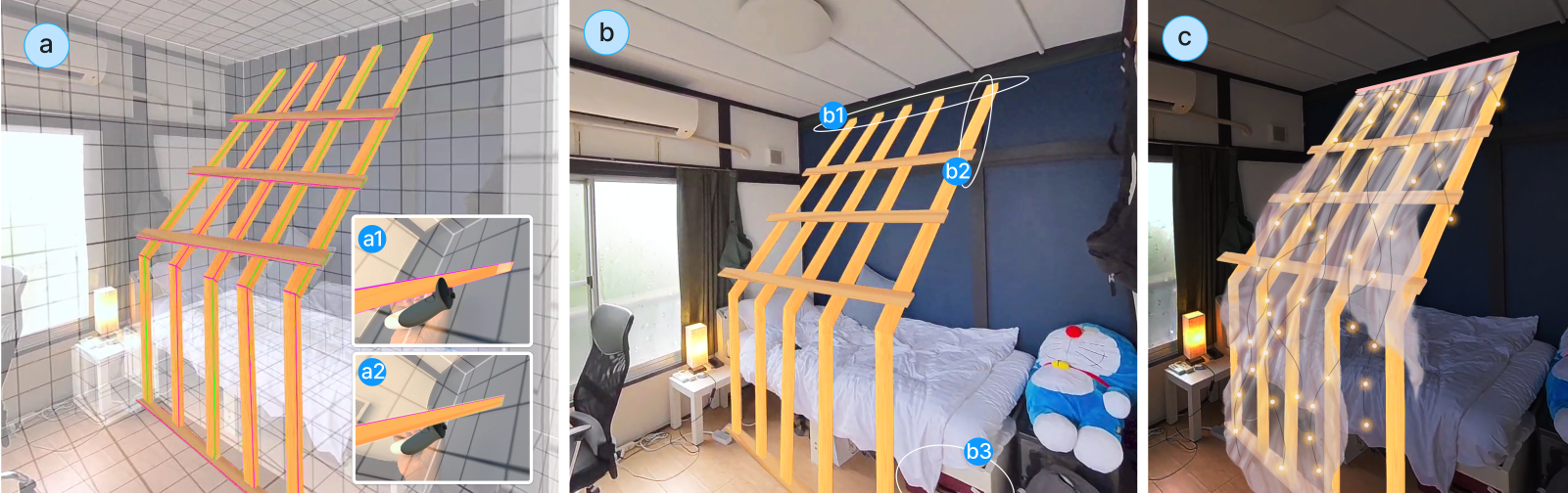
Similar to part-to-part interactions, we use physics-based collisions to prevent overlap between parts and the scene mesh, as seen in SnapToReality (Nuernberger et al., 2016). A scene mesh is a spatial representation of the surfaces of the user’s workspace, including walls, floors, tables, and other furniture. This mesh is created through in the scene-setup application of the headset. The scene mesh is automatically loaded into XR-penter’s spatial design interface, and it provides reference surfaces for part alignment, preventing an assembly from ”floating” in space. Fig. 5a shows the scene mesh bounding a canopy frame design.
(a) – (b) — (c)—
4.4. Cut Plan
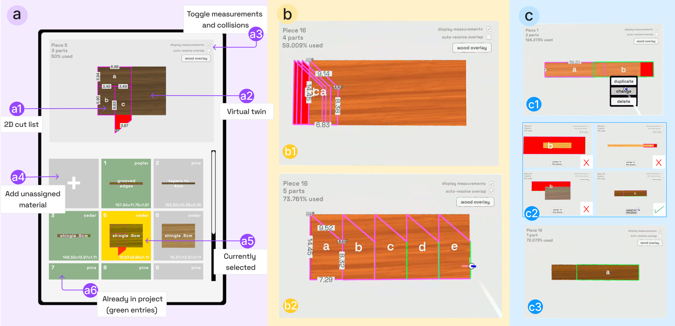
As users cut twins into parts and assemble them into a design, XR-penter generates an interactive cut plan (Fig. 6a). This plan is presented like a map showing the layout of parts on each scrap. The plan is displayed in 2D as default because we expect that users will not typically make resaw cuts. When needed, they can rotate the cut-plan around its y-axis.
User-Guided Packing
To support interactive packing, we use 2D collisions for automatically preventing overlap between parts. We add a small distance (e.g., 3 ) between parts to account for kerf, which is the material removed by the width of the blade when cutting. Users can customize the kerf-value based on their tools. Collider-aided packing can be utilized in either auto-resolve or manual mode.
In auto-resolve mode, cuts automatically resolve their intersections in real time (Fig. 6b2). As users create new 3D parts, each corresponding 2D part will be pushed into free space on the pattern, only overlapping when space is unavailable. We expect users to start making cuts in the auto-resolve mode and then switch to the manual mode as they move towards completing their design.
In manual mode, parts do not resolve their intersections until they are selected and moved around on the pattern (Fig. 6b1). This mode is ideal for the precise placement of individual parts when the rest of the pattern is finalized. Users edit individual part placements on the cut plan by selecting a part on the 2D canvas and moving it around or rotating it in increments. The part will automatically snap to the edges of the twin if close. Direct pattern manipulation can be performed in XR (with a ray interactor) or with a screen-based interface and a mouse for better precision.
Reassigning Parts
During the design process, a user may cut a part out of one scrap, before realizing it makes more sense to take it from a different material. Therefore, the cut plan provides a reassign feature that enables previewing a part to-scale next to other twins, along with any existing cuts on that scrap, allowing the user to assign the part to the best fit (Fig. 6c). The user can also opt to create unassigned parts that are not associated with any twins to estimate material they do not have on hand.
(a) – (b) — (c)—
4.5. Linking the Cut Plan and 3D Assembly
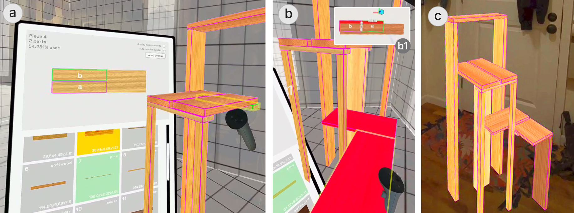
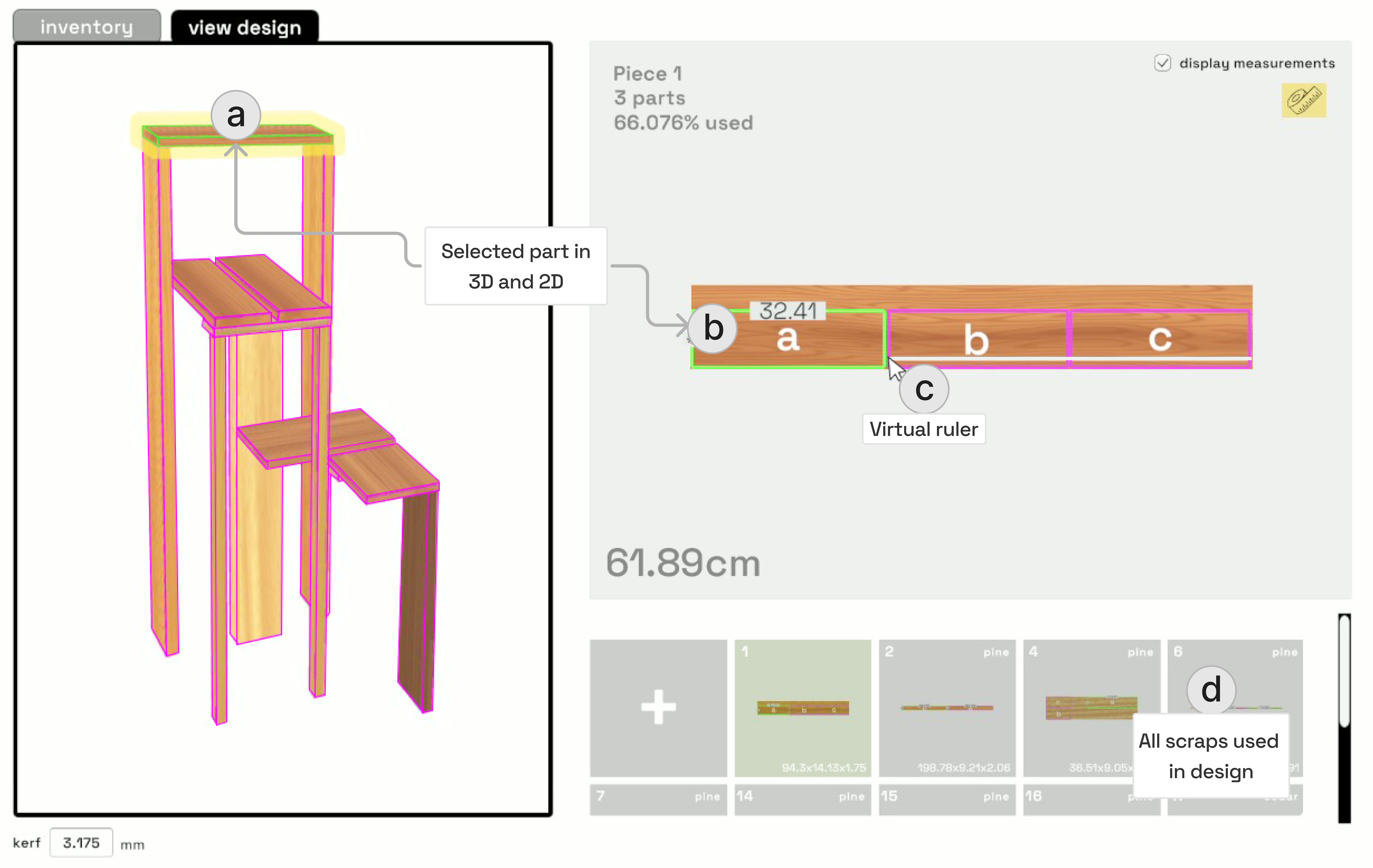
XR-penter provides real time, continuous feedback on material usage by linking the 2D cut plan with the 3D assembly. Each cut and its placement on the material are labeled with unique identifiers displayed in both 2D (on the cut plan) and 3D (within the spatial design interface). The system bridges these two views through a responsive highlight system (Fig. 7a).
Feedback
When a part is selected in XR, the corresponding scrap is selected in the virtual inventory, and the edges around the specific part are highlighted on the cut plan. Similarly, any adjustments made directly on the cut plan are reflected in 3D, with the same highlights. Before an adjustment is made, these highlights indicate what is about to change, helping the user verify that they are editing the correct edge or face.
The system provides feedback on material usage when new cuts are made and existing parts are adjusted. A warning system activates if a cut exceeds the available material boundaries or intersects with another part: the controller vibrates and the part turns bright red. The part will remain red, in both 2D and 3D, until the issue is corrected (Fig. 7b). Although most design edits are performed by manipulating parts in 3D space, certain situations necessitate selecting and resizing a part with a ray interactor on the 2D cut plan. This is useful when working with parts that are difficult to access in space, such as a high shelf.
Adjusting for the Grain Direction
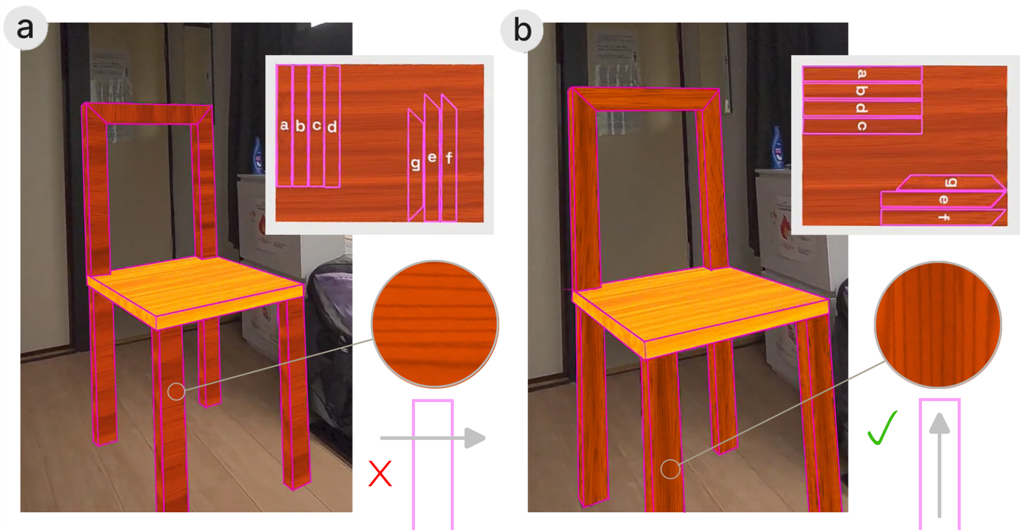
In addition to handling dimensions, the system enables users to adjust cuts based on the grain direction. The correct grain alignment is critical for structural integrity and aesthetic outcomes. The grain texture on each 3D part matches its relative 2D position on the scrap twin. If the grain direction of a part runs perpendicular to its length, the user can easily spot this and rotate the 2D cut accordingly (Fig. 8).
(a) – (b) — (c)—
Aligned Spatial References
The user may opt to manually align a virtual reference to each physical scrap. The reference template can be aligned to a scrap laying flat on the ground with the assistance of the floor plane of the scene mesh. Once the reference is flat, the user may nudge the physical scrap into place. Once aligned, the user can select the physical scrap with a ray interactor to either preview all proposed cuts on its surface (Fig. 9a) or re-draw the grain axis if incorrectly initialized (Fig. 9b). The cut preview can help users verify that planned cuts accommodate any physical surface features.
(a) – (b) — (c)—
4.6. Previewing the Design for Assembly
We provide a laptop/desktop interface that displays the entire 3D assembly and cut plan for users to fabricate their completed design (Fig. 10). When a part is selected in the 3D assembly, its corresponding cut plan entry is highlighted, and vice versa. Users may need to utilize a virtual measuring tape to verify dimensions when parts are not aligned with their scraps’ edges. In the current implementation, a user cannot edit the spatial model from the screen-based design preview, but they can return to XR mid-assembly to revise their design in response to fabrication errors. They may also need to adjust their XR model after re-registering materials due to incorrect measurements or changes from planing or sanding.
(a) – (b) — (c)—
5. Technical Implementation
XR-penter is implemented in Unity 2022.3.31, scripted in C#, and is designed to operate on the Meta Quest 3. We chose the Quest 3 for its widespread availability and full-color Passthrough camera, which enables users to view their surroundings through the headset. Our XR utilities were developed using the Meta XR All-in-One SDK. Geometry is generated at runtime using the ProBuilder Scripting API. Interactive menus were built with Unity’s UI Toolkit, and custom materials were created with the Shader Graph. We deploy XR-penter as a PCVR application to support the dual headset-PC interface. The headset must be connected to a computer to run the software, either through a link cable for reduced latency or via the Quest’s air-link feature for a tether-free experience, depending on the user’s preference.
Collisions
Our system uses Unity’s physics-based collision system for positioning 3D parts in spatial modeling and placing 2D cuts on the cut plan. We changed the default contact offset that controls the precision of 3D collisions, to , which was the minimum value required for parts to stick together without gaps. If a user grabs a 3D part and moves it into existing geometry, the system will temporarily allow the violation until the grab is released, thereby pushing the part out along the saved normal direction of the collision to resolve the intersection. On the 2D cut plan, every time a part is generated, resized, or re-positioned, we check for any existing overlap every frame, activating our warning systems accordingly. These 2D colliders assist users in resolving this overlap using Unity 2D Rigidbodies. We add kerf padding to the cut plan by dilating the colliders by half the blade width.
Spatial Anchors
In situ design creation is supported by Meta’s Mixed Reality Utility Kit’s (MRUK) spatial anchors, locking 3D parts into their user-defined positions in reference to the real world. If a user takes off their headset and walks away, their virtual assembly will remain in the same spot on their return. These anchors are used to position virtual references on top of the physical material. Although there is no object tracking involved, the reference will stay aligned with its scrap unless it is moved. MRUK additionally handles loading in the scene mesh as a collision surface.
Procedural Wood Shader
Our interactive wood shader approximates the wood grain with tri-planar mapped voronoi noise. We introduce natural-looking variation to the grain’s curvature through a smooth-stepped sine wave function that distorts the noise’s linear flow, further stylized with layers of color and simple noise. The grain direction is initialized by rotating the noise around the x-axis.
6. Case Study
We ran a case study with a self-taught woodworker with 10 years of experience designing and building DIY wood assemblies to test XR-penter’s workflow in practice. Previously interviewed in our formative evaluation (P5), he expressed enthusiasm in exploring the resulting system. The woodworker was unpaid, and we agreed that he to keep the resulting furniture.
The woodworker led the design and fabrication, while an author operated the system. The author used the headset to model designs, incorporating feedback from the woodworker, who viewed the XR feed on a laptop. We chose this setup because the full user interface is not optimized for first-time users. As the system’s developer, the author could focus on utilizing all of the features without being distracted by minor technical issues. Acknowledging that this setup deviates from the intended use-case of XR-penter’s, our goal is not to objectively evaluate the system but to demonstrate its capabilities and technical feasibility.
We aimed to build unique and functional furniture for a university dorm with simple tools (measuring tape, handsaw, and drill) and recycled materials. We asked around in the community to retrieve scraps, and quickly found a construction site that gave us a free pile of discarded wood. The case study spanned two and a half days, including the half a day for sourcing wood. We did not plan what to build in advance, so we were free to improvise based on the available material and the layout of the dorm.
6.1. Creating the Virtual Inventory
The first step was to register our material into XR-penter’s virtual inventory. Out of the 25 pieces of scrap wood given to us, we selected 21 pieces (Fig. 11a) for registration. The woodworker used a marker to number each piece, and input its dimensions, material type, and approximate color into our registration interface using a laptop (Fig. 11d). There were eight scraps that had considerable imperfections (mostly warping or tapering). These entries were “tagged” with a note so we could look out for them during the design. The registration took about an hour to complete. Although time-consuming, physically handling each scrap to record its details provided us a full tactile understanding of the material. For example, scrap #16 looked normal, but was wet, whereas scrap #11 looked rotten, but was unexpectedly sturdy. Throughout this process, we imagined specific functions for each scrap. Based on these material interactions, the woodworker suggested we build a chair and a smaller, undetermined design. We proceeded with the chair.
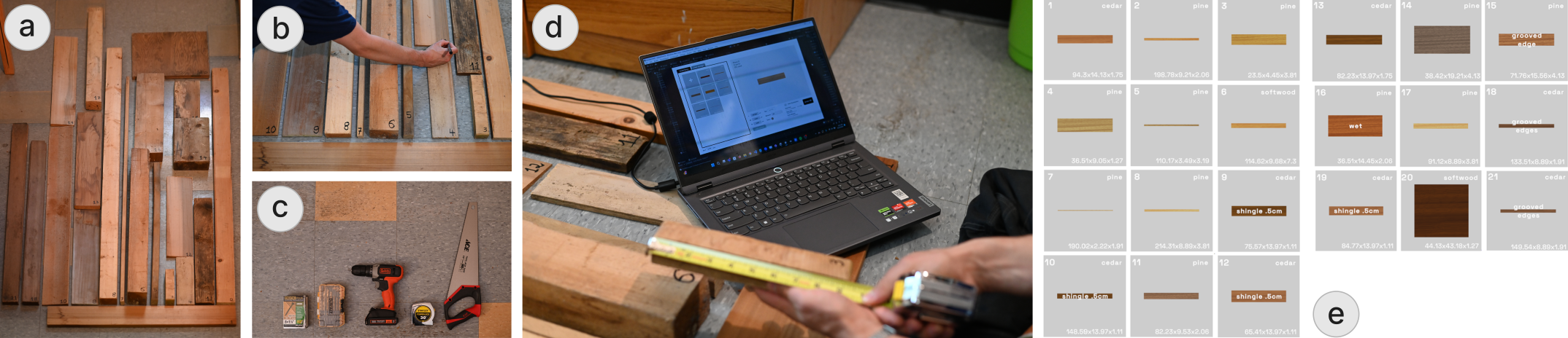
(a) – (b) — (c)—
6.2. Chair
Before starting to design in XR, the author used the Quest 3’s scene setup to scan the dorm room. It took 5 minutes to create and clean the scan. The scan was automatically loaded into XR-penter’s XR environment, along with our saved wood inventory. The woodworker started to sketch a potential design on paper (Fig. 12a) during the registration step, but we were unsure how it would map to our scraps. He recommended we build the frame of the chair using our sturdiest wood: scraps #8 and #17, and the author used XR to confirm that these pieces could be cut to yield enough material. To ensure the frame fit his body, the woodworker sat on two stacked tubs, and the author measured the virtual twins to a comfortable height using linked groups (Fig. 12b2). Our original frame only fit a seat made of two equal-width planks side-by-side, leaving an awkward gap at the front (Fig. 12c1). Instead of cutting a third plank across its length, which is tedious with a handsaw, the author pulled the frame forward, lengthening the seat to fit three full-width planks (Fig. 12d1).
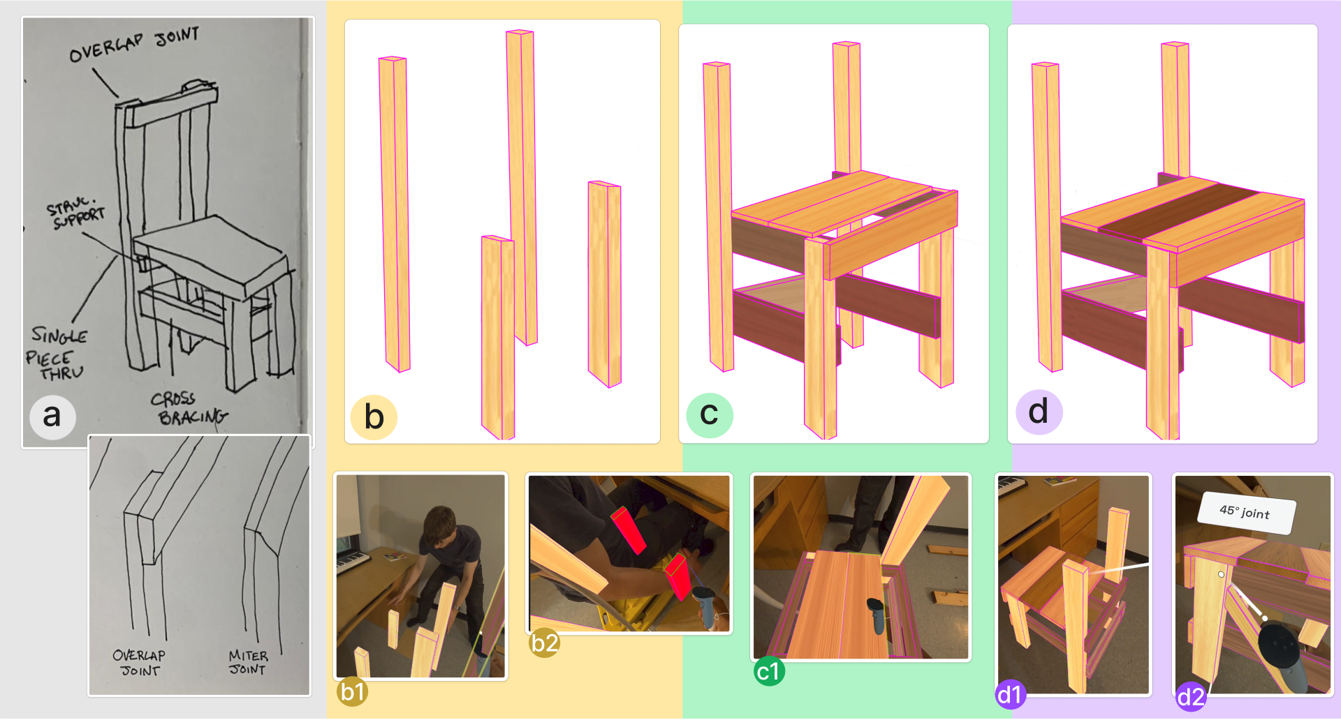
(a) – (b) — (c)—
The woodworker guided the author in adding reinforcements and a backrest to finalize the design. The reinforcements were cut at via snapping provided by the system (Fig. 12d2). The author assigned scraps #12 and #9 to the backrest because they were tagged as “shingled”, and the woodworker wanted lighter planks to balance out the heavy back posts. The author used XR-penter to split their lengths relative to the chair, and we concluded the 50 minutes XR design session. The woodworker referenced the final cut plans generated with the system (Fig. 13a) on XR-penter’s laptop interface. The built chair took 4 hours to fabricate and is appropriately sized for the woodworker’s body (Fig. 13).
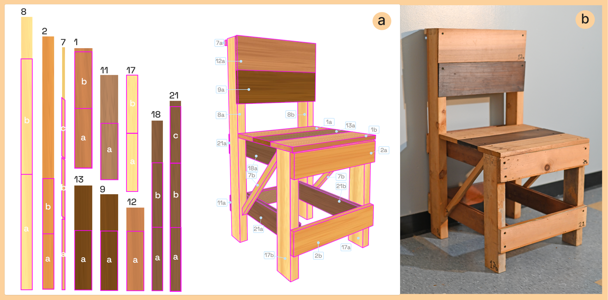
(a) – (b) — (c)—
6.3. Slant Shelf
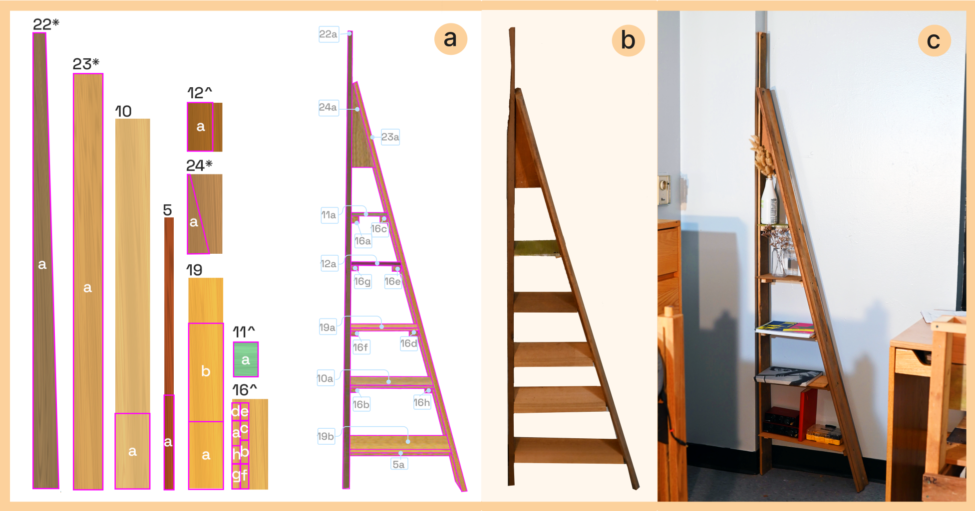
We also wanted to test the ability of XR-penter to assist with a relatively simpler design, so we decided to create a shelving unit. The woodworker wanted the shelf to be light, involving thin pieces of wood that are easy to cut. There were no such pieces among the leftovers from the chair, so he registered three new scraps to the existing inventory that persisted from our last session. The woodworker discarded these scraps earlier because they were tapered and/or grooved, but they provided the length needed for a taller structure. As he handled the new scraps, the woodworker realized #22 fit perfectly into a small, odd corner that jutted out of a wall of the dorm, and leaned scrap #23 against it to create a lean-to structure. This discovery happened outside of XR, but it wasn’t obvious how to develop the rest of the design with the few scraps we had left, so we returned to XR-penter.
Once in XR, the author positioned virtual twins into the same lean-to configuration using the scene mesh and cut out a triangle that fit in the tip for reinforcement. They then brought the remaining cut-offs into the scene as shelf candidates, ordered parts by the tapering widths of the frame, and let the collisions between the two framing scraps push them into a flush position. During this process, the inventory motivated us to feature some of our unique material. For example, the backside of scrap #11 was bright green, likely from algae. The woodworker thought this was appealing, and re-registered its color as green, leading to it being featured as our top shelf. The XR design session lasted 20 minutes and Fig. 14a shows our generated cut plans. The built shelf took 1.5 hours to fabricate, fits into the odd corner and can hold a variety of items (Fig. 14c).
6.4. Material Usage
Our final virtual inventory contained 24 scraps. 31.08% of this wood was used for the chair, and 15.22% for the shelf, totaling 46.03% of our original scraps. We deliberately created cut plans that preserved larger scraps, so six of our left-over scraps had a surface area larger than 0.15 , making them substantial material for future projects. The smaller off-cuts can still be creatively recycled with our system.
We found that XR-penter’s spatial modeling and anchoring systems were precise enough to determine material usage in advance. As the woodworker fabricated the designs, he used the dimensions from the cut plan for the frame of the chair and the shelves of the shelving unit, referencing the partial assemblies to determine the remaining cuts. He found this to be more intuitive, because parts naturally shift slightly during fabrication. As predicted by our system, we had sufficient material to cut all parts. The average deviation between the cut plan and fabricated lengths was 7 mm for the chair and 3 mm for the shelving unit. The deviation for the chair was higher because its framing parts were imperfectly measured.
(a) – (b) — (c)—
6.5. Reflection
A key strength of our system in practice was that it facilitated decision making in situ. Even in a standard sized dorm room, we frequently used the scene mesh for alignment (Fig. 15a,e), and the visual context of the surroundings to inform design decisions (Fig. 15b,c,d). For example, when designing the chair, the author could quickly assemble a frame suited to the woodworker’s body and obtain immediate feedback from him. The woodworker later shared that ”using actual objects and spaces themselves to measure things, as opposed to taking a tape-measure and then manually drawing it… This really suited the way I work.”
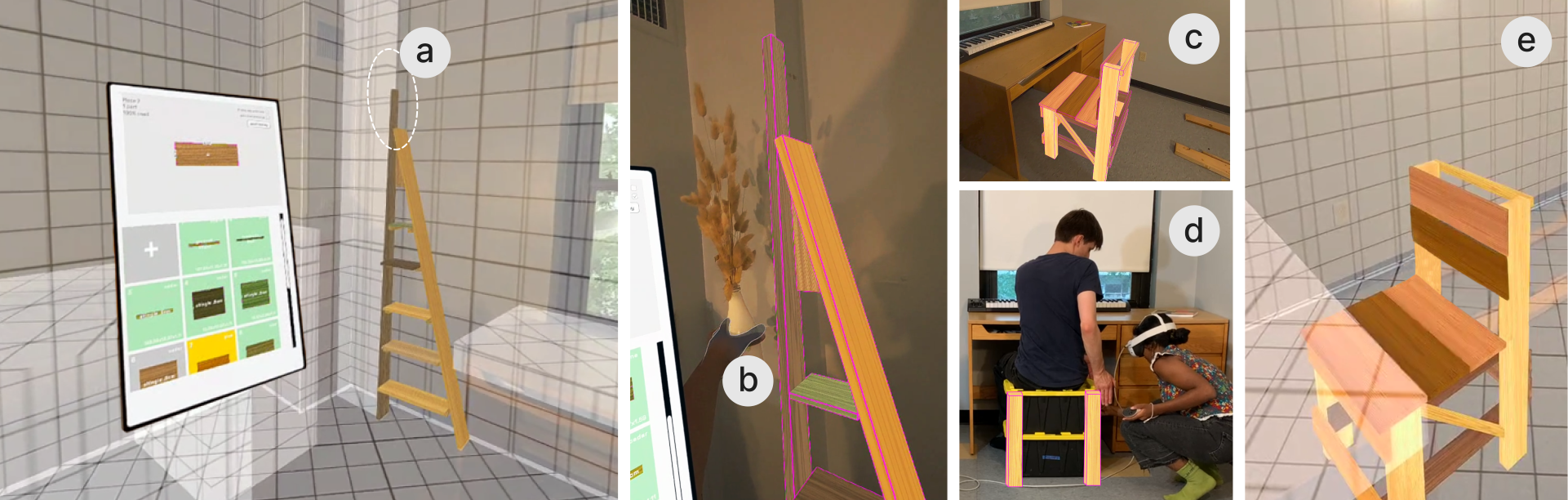
(a) – (b) — (c)—
Coupling the virtual inventory with physical scraps helped us identify specific uses for varied materials that otherwise proved difficult to visualize. Even after the author defined the chair’s rough proportions in situ, they were not sure if they had enough material for its surfaces, so they relied on material usage indicators and linked editing to determine which scraps to cut from. When designing the shelf, finding a practical shelving arrangement that minimized cuts was our biggest challenge because each shelf position depended on its length. XR-penter allowed us to preview all shelves at once and iterate towards a functional layout. The woodworker felt that XR-penter’s inventory complemented the exploratory nature of his practice: “This system is faster than anything I’ve used to visualize what I can make with scraps… It feels like the scraps are this finite resource we can freely allocate…and play with.”
An unexpected affordance of our system was our ability to collaborate within it, as XR-penter was originally designed for a single user with woodworking knowledge. The author did not have prior experience with woodwork design, but prototyping in XR-penter allowed them to express design intent in a way that the woodworker could understand and guide. A major limitation observed by the woodworker was the need to repeatedly travel between the physical material (to check the physical cut overlays) and the 3D assembly. Since the scraps we worked with lacked localized surface features, we generated cut plans in auto-resolve mode and accepted the compact packing configurations. However, if our scraps had specific features to design around, this approach would not have been sufficient.
7. Feedback From Target Users
We held feedback sessions with eight (U1-U8) hobbyist woodworkers, ages 21-40, to learn how they might feel about engaging with XR-penter. All participants had experience building functional items with scrap wood, had used an XR headset at least once, and were recruited as unpaid volunteers from the local community. As indicated by our case study, the design and fabrication of a full piece of furniture is a time and labor-intensive process. Meanwhile, user-testing an isolated feature would not capture the full experience of creating a situated, material-aware design. Therefore, we presented a video including the system’s motivation, walk-through and case study results (refer to the video figure) inspired by the evaluation approach of Hybrid Carpentry (Zoran et al., 2013), which was followed up with a short, open-ended XR design session so participants could try the system themselves.
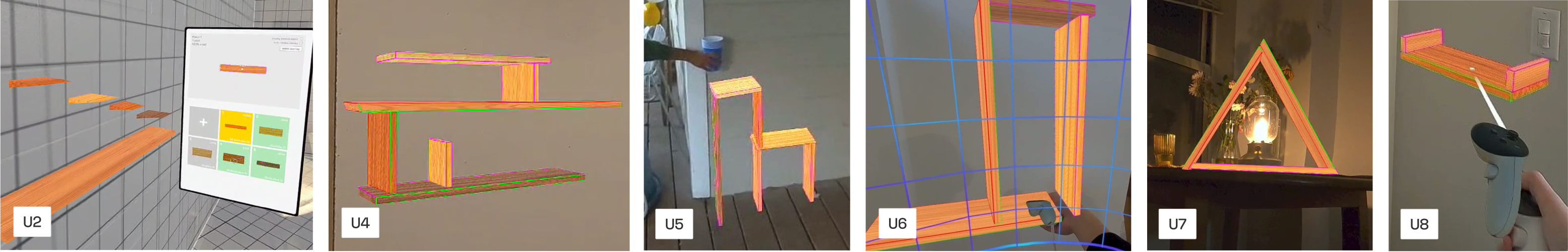
Each session lasted 1 hour, with 45 minutes dedicated to semi-structured discussion, including watching the video, and 15 minutes for hands-on use. The XR portion started with a 10 minute author-guided tutorial covering core XR-penter mechanisms: accessing the inventory, positioning and cutting parts in 3D, duplicating parts for linked edits and re-assigning parts. Participants spent their last 5 minutes with XR-penter freely designing a simple shelving unit (Fig. 16) using five pre-registered scraps, giving us oral feedback both during and after headset use. We share our findings below.
a,b,c
7.1. Usability of the XR Interface
Every participant could grasp the XR-penter’s XR modeling interface during the 10 minute tutorial. U4 said our operations to “cut” wood felt “really straightforward…you just need to select the edges you want to push in or push out”. U2 thought that the cut operations “felt very physical”. U6 shared, ”[I like] that I can actually see the [virtual] wood in real life, it’s like I’m building it! It feels easier than CAD.” U2, U4, U5, and U7 felt that XR-penter’s spatial interface could help them explore their design space in an adaptive way. U2 shared, “I love the creativity and the free flow of placing [virtual] wood wherever I want,” as she usually gets ”stuck” thinking about “L-brackets and stuff.” However, U1 felt that placing each part in space by hand felt “tedious” and said he would strongly prefer to adjust pre-defined designs, rather than creating a design from scratch. We also observed limitations with our current spatial modeling mechanisms: all participants became frustrated by 3D parts unexpectedly ”floating away” because of our 3D collision handling and experienced difficulty aligning them in flush arrangements. U7 also shared that she wouldn’t feel confident designing complex objects in XR (referencing the chair from the case study) without ”some sort of a guide,” such as a sample 3D model to reference.
7.2. Designing In Situ
All participants valued XR-penter’s support for designing in context. U1 thought XR-penter ”is most useful for environment specific projects, [like] a shelf that fits an exact space.” U3 reflected on past experiences designing and fabricating furniture that did not quite “fit” in its intended space, and felt that XR-penter could help him prevent such issues. U1, U2, U4, and U6, with experience using XR to preview furniture/product designs, appreciated the ability to edit their design in context, a feature lacking in the systems they had previously used. During our XR demos, each participant could successfully align their shelves with the scene mesh and felt that it helped them verify fit. However, U5 suggested using a more transparent texture for the scene mesh to improve visibility of the environment behind it. After trying our system, U3 expressed interest in using it to mock-up a wooden stand he was planning to build ”just to see how it would look and fit in the space”. U5, U6, and U8 indicated they would want to use XR-penter for larger, environment-specific projects rather than small builds. U5 felt that “[getting out an XR headset] might not be worth the effort” for a small, standalone object.
7.3. Designing with Scraps
U5, who builds functional structures for her farm, noted that XR-penter’s scrap inventory could ”increase [her] creativity” while motivating her to be ”sustainable”. Participants generally felt that XR-penter’s feedback features, such as red indicators for material limits, could ensure their designs remain feasible. U4 shared, ”I like the blocks turning red because it lets me know how much material I still have left,” as he edited a part in space. U2 felt like she could experiment in XR instead of “wasting a real piece of wood,” by letting the 2D cut plan automatically generate as she worked. However, U3 found it difficult to follow “the relationship between the stock and cut part” because they were “changing both in space and on the [2D] menu”. He explained that he does not think about his 3D designs in terms of 2D parts until it is time to acquire material. Although participants appreciated the display of grain and color on the scraps, nearly everyone expressed interest in using scanned textures instead of initializing this information themselves. The only exception was U4, who preferred the simulated textures for their “simplicity.”
7.4. Reflection
We designed XR-penter to address challenges faced by ”DIY woodworkers,” recognizing that this group encompasses a broad range of approaches. Our feedback sessions helped verify our target audience: U2, U4, U5 and U7, who build quick, functional projects from scraps, liked XR-penter’s material-aware features the most. In contrast, U1 and U3, who work on more sophisticated, time-consuming builds, expressed a preference for purchasing new materials for a predefined design rather than adapting the design to fit available scraps. They were understandably skeptical of our system’s scrap inventory. While U6 and U8 enjoy working with scraps for detailed wood craft, they found XR-penter’s design space too limited for their needs. Therefore, we can conclude that XR-penter is most useful for DIY woodworkers who prioritize material-driven, adaptive workflows over intricate craftsmanship. This group are not necessarily novices; they are simply less outcome-oriented in their approach.
8. Discussion
In this section, we discuss findings from our case study and feedback sessions, and present transferable principles for designing systems that aim to consider material and/or space in a similar way.
Interactive Design vs. Fabrication for Scraps.
Currently, XR-penter supports interactive design, but not fabrication. We assume that users will finalize their design before beginning fabrication, with adjustments only made to address unexpected errors during the build. Furthermore, supporting fabrication in XR would be unwieldy and potentially dangerous with our current headset. However, we acknowledge that working with scraps is an inherently nonlinear process. XR-penter addresses this by encouraging users to explore their full design space before making physical cuts, reducing the likelihood of costly mistakes while supporting the improvisation necessitated by scraps. In general, similar material-aware systems should prioritize iterative exploration during the design phase, providing users with tools to visualize, manipulate, and “test” their designs before moving to physical fabrication. At the same time, integrating some features that accommodate mid-fabrication adjustments—such as material re-assignment or pattern editing—can ensure the system meets the reality of manual workflows.
Digital Design with Non-Standard Materials.
By virtue of being in XR, our system allows users to engage with real wood during their design process. We expect users to naturally reference both the virtual inventory and their physical inventory when selecting suitable scraps for their design, which is in line with the observation that tactile feedback is essential for raw material crafts (Crevels, 2023). We ensured that all spatial design operations outlined can be performed with a single controller, so the other hand is free to interface with physical material (we had previously considered enabling the headset’s built in hand-tracking, but it proved too imprecise in its current state). Based on feedback from formative interviews, we chose user-guided layout creation over automated material optimization, as this approach better accommodates the variability of natural material. During our case study, both the woodworker and author relied on physical interactions with material to assign specific scraps to different parts of our designs. If the system had automatically made all assignments, the resulting designs would not have met our structural or aesthetic vision.
Creative Design in Situ.
From our formative interviews, we identified a need for systems that help woodworkers visualize their designs in context, and this was unanimously reaffirmed in our feedback sessions. Furthermore, these sessions helped us formulate a new insight: participants found value in the ability to create designs directly in situ. U1, for instance, had previously tried an AR CAD plugin to preview his woodwork designs, but disliked having to switch between AR and his computer every time he made an adjustment. He appreciated that XR-penter allows users to “directly adjust things in place.” While in situ design systems naturally embed spatial context into the design process, we observe that they benefit from additional constraints: since XR-penter does not utilize parametric templates, features such as material usage limits and environment snapping are necessary to guide the design process. Our feedback sessions revealed that users would appreciate even more constraints, such as structural validation. We also found that supporting a simple set of design operations (instead of the complexity of commercial CAD) means designs created with our system can be fabricated with basic hand/power tools and are easier to manipulate in XR.
9. Future Work
Multi-User Scenarios.
Two of our participants from our feedback sessions, U2 and U3, are a couple who team up on woodworking projects. After seeing the case study’s two-person setup, they expressed a desire in having two headsets for collaboration, so they could develop their designs in shared spatial context. However, they suggested that only one person operates the system while the other directs, so the non-headset wearer can focus on giving feedback and preparing materials. Future work might explore both multi-headset and asymmetric setups for co-design in XR.
Scanned Inventory.
After challenges visualizing localized imperfections during our case study and feedback from most participants that manual registration seemed tedious, we consider integrating a 3D scanning workflow as a promising next step (Meta plans to provide developer Passthrough camera access in early 2025444Meta 2024 Developer Keynote https://developers.facebook.com/m/meta-connect-developer-sessions/developer-keynote). However, we acknowledge that an important part of woodworking involves the physical inspection and engagement of materials (Crevels, 2023). Therefore, a future iteration of XR-penter can explore a hybrid approach combining the convenience of a scanned inventory with tactile material interactions. For example, a woodworker can optionally ”tag” scanned features with more detail after manually inspecting their material.
Currently, scrap registration in XR-penter occurs on the laptop because it is difficult to read a tape measure at the Quest’s current Passthrough resolution. We acknowledge that switching between the headset and laptop breaks flow, and we anticipate in-headset registration to become viable as camera technologies advance, perhaps aided by marker-based tracking (Lau et al., 2012; Jahn et al., 2024) or gestural localization (Htet Kyaw et al., 2024).
Expanded Modeling Utilities.
Our system only creates 8-cornered rectilinear shapes, but U1, U6 and U8 expressed interest in support for additional joints and cuts, such as dados, rabbets, and grooves. Six of our feedback session participants also expressed a strong interest in having access to ”templates” for standard structures, such as chairs, stairs and tables. This could expand to integrating the situated parametric design features found in pARam (Stemasov et al., 2024) with the material-awareness of XR-penter. For instance, a chair ”template” could allow users to adjust parameters such as seat height or backrest angle, while the system prompts the user to assign scraps to the design.
Structural Design Guidance.
Although our interface is geared towards casual makers, it necessitates some tacit woodworking knowledge. For example, the woodworker we collaborated in the case-study was experienced in constructing stable wood assemblies, and knew how to correctly reinforce our virtual designs. In contrast, completely inexperienced makers may not know how to create a sturdy structure. Five of our feedback session participants shared that they wanted the system to tell them if their designs were structurally sound. Accordingly, we could provide feedback on physical validity, as seen in previous works (Umetani et al., 2012; Saul et al., 2010). Integrating these approaches with our XR system could enable more interactive evaluations, allowing users to ’push’ on a virtual table or ’sit’ on a chair to simulate how their designs might respond.
10. Conclusion
In this paper, we introduced XR-penter, an XR system designed to support material-aware, in situ design for DIY woodworking projects. XR-penter enables users to plan and execute designs that are within their functional reach. Our case study demonstrated the ability of our proposed system to facilitate design with irregular materials, highlighting its potential to bridge the gap between digital planning and manual assembly for casual makers. Our user feedback sessions show that DIY woodworkers appreciated the system’s support of creative, situated design with scrap materials and helped verify the target audience for such tools. By contributing a digital tool that enhances the way woodworkers naturally approach projects, we can enable them to experiment and plan more effectively without losing the tactile, hands-on experience of their craft.
Acknowledgements.
We extend special thanks to woodworker Geoffrey Hazard, whose skill and insight were invaluable in demonstrating our system via case study. We also thank everyone who generously volunteered their time for our interviews and feedback sessions, as well as Bo Zhu and Haoran Xie for their ongoing support. This research was supported by the NSF IRES program (Award: 2433313), JST ACT-X (Award: JPMJAX210P), JST AdCORP (Award: JPMJKB2302), JSPS KAKENHI (Award: JP23K19994) and a collaborative research fund between Mercari Inc. R4D and RIISE, University of Tokyo.References
- (1)
- Agrawal et al. (2015) Harshit Agrawal, Udayan Umapathi, Robert Kovacs, Johannes Frohnhofen, Hsiang-Ting Chen, Stefanie Mueller, and Patrick Baudisch. 2015. Protopiper: Physically Sketching Room-Sized Objects at Actual Scale. In Proceedings of the 28th Annual ACM Symposium on User Interface Software & Technology. ACM, Charlotte NC USA, 427–436. https://doi.org/10.1145/2807442.2807505
- Arisandi et al. (2014) Ryan Arisandi, Mai Otsuki, Asako Kimura, Fumihisa Shibata, and Hideyuki Tamura. 2014. Virtual Handcrafting: Building Virtual Wood Models Using ToolDevice. Proc. IEEE 102, 2 (Feb. 2014), 185–195. https://doi.org/10.1109/JPROC.2013.2294243 Conference Name: Proceedings of the IEEE.
- Baudisch et al. (2019) Patrick Baudisch, Arthur Silber, Yannis Kommana, Milan Gruner, Ludwig Wall, Kevin Reuss, Lukas Heilman, Robert Kovacs, Daniel Rechlitz, and Thijs Roumen. 2019. Kyub: A 3D Editor for Modeling Sturdy Laser-Cut Objects. In Proceedings of the 2019 CHI Conference on Human Factors in Computing Systems. ACM, Glasgow Scotland Uk, 1–12. https://doi.org/10.1145/3290605.3300796
- Beltagui et al. (2021) Ahmad Beltagui, Achilleas Sesis, and Nikolaos Stylos. 2021. A bricolage perspective on democratising innovation: The case of 3D printing in makerspaces. Technological Forecasting and Social Change 163 (Feb. 2021), 120453. https://doi.org/10.1016/j.techfore.2020.120453
- Besserer et al. (2021) Arnaud Besserer, Sarah Troilo, Pierre Girods, Yann Rogaume, and Nicolas Brosse. 2021. Cascading Recycling of Wood Waste: A Review. Polymers 13, 11 (May 2021), 1752. https://doi.org/10.3390/polym13111752
- Bezci (2016) Ismail Bezci. 2016. Do It Yourself: A Methodological Study in Furniture Design. In 3rd International Multidisciplinary Scientific Conference on Social Sciences and Arts, Vol. 16. 313–324. https://doi.org/10.5593/SGEMSOCIAL2016/B43/S15.038
- Bonvoisin et al. (2017) Jérémy Bonvoisin, Jahnavi Krishna Galla, and Sharon Prendeville. 2017. Design Principles for Do-It-Yourself Production. In Sustainable Design and Manufacturing 2017, Giampaolo Campana, Robert J. Howlett, Rossi Setchi, and Barbara Cimatti (Eds.). Springer International Publishing, Cham, 77–86. https://doi.org/10.1007/978-3-319-57078-5_8
- Bourgault et al. (2023) Samuelle Bourgault, Pilar Wiley, Avi Farber, and Jennifer Jacobs. 2023. CoilCAM: Enabling Parametric Design for Clay 3D Printing Through an Action-Oriented Toolpath Programming System. In Proceedings of the 2023 CHI Conference on Human Factors in Computing Systems. ACM, Hamburg Germany, 1–16. https://doi.org/10.1145/3544548.3580745
- Bunn (1999) Stephanie Bunn. 1999. The Importance of Materials. Journal of Museum Ethnography 1, 11 (1999), 15–28. https://www.jstor.org/stable/40793620 Publisher: Museum Ethnographers Group.
- Camburn and Wood (2018) Bradley Camburn and Kristin Wood. 2018. Principles of maker and DIY fabrication: Enabling design prototypes at low cost. Design Studies 58 (Sept. 2018), 63–88. https://doi.org/10.1016/j.destud.2018.04.002
- Cousin et al. (2023) Tim Cousin, Latifa Alkhayat, Natalie Pearl, Christopher B. Dewart, and Caitlin Mueller. 2023. Wild Wood Gridshells: Mixed-Reality Construction of Nonstandard Wood. Technology|Architecture + Design 7, 2 (July 2023), 216–231. https://doi.org/10.1080/24751448.2023.2245725 Publisher: Routledge _eprint: https://doi.org/10.1080/24751448.2023.2245725.
- Crevels (2023) Eric Crevels. 2023. Coarse epistemes: Skill, craftsmanship and tacit knowledge in the grit of the world. Perspectives on Tacit Knowledge in Architecture (2023), 13–29.
- Deshpande et al. (2022) Himani Deshpande, Jin Yu, Akash Talyan, and Noah Posner. 2022. Upcycling discarded HDPE plastic bags for creative exploration in product design. In DRS2022. Bilbao. https://doi.org/10.21606/drs.2022.266
- Dew and Rosner (2019) Kristin N. Dew and Daniela K. Rosner. 2019. Designing with Waste: A Situated Inquiry into the Material Excess of Making. In Proceedings of the 2019 on Designing Interactive Systems Conference (DIS ’19). Association for Computing Machinery, New York, NY, USA, 1307–1319. https://doi.org/10.1145/3322276.3322320
- Dogan et al. (2021) Mustafa Doga Dogan, Steven Vidal Acevedo Colon, Varnika Sinha, Kaan Akşit, and Stefanie Mueller. 2021. SensiCut: Material-Aware Laser Cutting Using Speckle Sensing and Deep Learning. In The 34th Annual ACM Symposium on User Interface Software and Technology (UIST ’21). Association for Computing Machinery, New York, NY, USA, 24–38. https://doi.org/10.1145/3472749.3474733
- Dogan et al. (2022) Mustafa Doga Dogan, Patrick Baudisch, Hrvoje Benko, Michael Nebeling, Huaishu Peng, Valkyrie Savage, and Stefanie Mueller. 2022. Fabricate It or Render It? Digital Fabrication vs. Virtual Reality for Creating Objects Instantly. In Extended Abstracts of the 2022 CHI Conference on Human Factors in Computing Systems. Association for Computing Machinery, 5. https://doi.org/10.1145/3491101.3516510
- Efrat et al. (2016) Tamara Anna Efrat, Moran Mizrahi, and Amit Zoran. 2016. The Hybrid Bricolage: Bridging Parametric Design with Craft through Algorithmic Modularity. In Proceedings of the 2016 CHI Conference on Human Factors in Computing Systems. ACM, San Jose California USA, 5984–5995. https://doi.org/10.1145/2858036.2858441
- Hoadley (2000) R. Bruce Hoadley. 2000. Understanding Wood: A Craftsman’s Guide to Wood Technology. Taunton Press.
- Htet Kyaw et al. (2024) Alexander Htet Kyaw, Lawson Spencer, Sasa Zivkovic, and Leslie Lok. 2024. Gesture Recognition for Feedback Based Mixed Reality and Robotic Fabrication: A Case Study of the UnLog Tower. In Phygital Intelligence, Chao Yan, Hua Chai, Tongyue Sun, and Philip F. Yuan (Eds.). Springer Nature, Singapore, 331–345. https://doi.org/10.1007/978-981-99-8405-3_28
- Jahn et al. (2024) Gwyllim Jahn, Cameron Newnham, and Nick Berg. 2024. Mixed Reality Carpentry. In RobArch 2024. Toronto. https://www.researchgate.net/publication/381189449_Mixed_Reality_Carpentry
- Johns et al. (2023) Ryan Luke Johns, Martin Wermelinger, Ruben Mascaro, Dominic Jud, Ilmar Hurkxkens, Lauren Vasey, Margarita Chli, Fabio Gramazio, Matthias Kohler, and Marco Hutter. 2023. A framework for robotic excavation and dry stone construction using on-site materials. Science Robotics 8, 84 (Nov. 2023), eabp9758. https://doi.org/10.1126/scirobotics.abp9758 Publisher: American Association for the Advancement of Science.
- Kim et al. (2019) Yoonji Kim, Youngkyung Choi, Hyein Lee, Geehyuk Lee, and Andrea Bianchi. 2019. VirtualComponent: A Mixed-Reality Tool for Designing and Tuning Breadboarded Circuits. In Proceedings of the 2019 CHI Conference on Human Factors in Computing Systems. ACM, Glasgow Scotland Uk, 1–13. https://doi.org/10.1145/3290605.3300407
- Koo et al. (2017) Bongjin Koo, Jean Hergel, Sylvain Lefebvre, and Niloy J. Mitra. 2017. Towards Zero-Waste Furniture Design. IEEE Transactions on Visualization and Computer Graphics 23, 12 (Dec. 2017), 2627–2640. https://doi.org/10.1109/TVCG.2016.2633519
- Kyaw (2023) Alexander Htet Kyaw. 2023. Active Bending in Physics-Based Mixed Reality: The design and fabrication of a reconfigurable modular bamboo system. In Dokonal, W, Hirschberg, U and Wurzer, G (eds.), Digital Design Reconsidered - Proceedings of the 41st Conference on Education and Research in Computer Aided Architectural Design in Europe (eCAADe 2023) - Volume 1, Graz, 20-22 September 2023, pp. 169–178. CUMINCAD. https://papers.cumincad.org/cgi-bin/works/paper/ecaade2023_447
- Larsson et al. (2019) Maria Larsson, Hironori Yoshida, and Takeo Igarashi. 2019. Human-in-the-loop fabrication of 3D surfaces with natural tree branches. In Proceedings of the ACM Symposium on Computational Fabrication. ACM, Pittsburgh Pennsylvania, 1–12. https://doi.org/10.1145/3328939.3329000
- Larsson et al. (2020) Maria Larsson, Hironori Yoshida, Nobuyuki Umetani, and Takeo Igarashi. 2020. Tsugite: Interactive Design and Fabrication of Wood Joints. In Proceedings of the 33rd Annual ACM Symposium on User Interface Software and Technology. ACM, Virtual Event USA, 317–327. https://doi.org/10.1145/3379337.3415899
- Lau et al. (2012) Manfred Lau, Masaki Hirose, Akira Ohgawara, Jun Mitani, and Takeo Igarashi. 2012. Situated modeling: a shape-stamping interface with tangible primitives. In Proceedings of the Sixth International Conference on Tangible, Embedded and Embodied Interaction. ACM, Kingston Ontario Canada, 275–282. https://doi.org/10.1145/2148131.2148190
- Lau et al. (2011) Manfred Lau, Akira Ohgawara, Jun Mitani, and Takeo Igarashi. 2011. Converting 3D furniture models to fabricatable parts and connectors. In ACM SIGGRAPH 2011 papers. ACM, Vancouver British Columbia Canada, 1–6. https://doi.org/10.1145/1964921.1964980
- Lau et al. (2010) Manfred Lau, Greg Saul, Jun Mitani, and Takeo Igarashi. 2010. Modeling-in-context: user design of complementary objects with a single photo. In Proceedings of the Seventh Sketch-Based Interfaces and Modeling Symposium. Eurographics Association, Annecy, France, 17–24.
- Lee et al. (2018) Bokyung Lee, Joongi Shin, Hyoshin Bae, and Daniel Saakes. 2018. Interactive and Situated Guidelines to Help Users Design a Personal Desk that Fits Their Bodies. In Proceedings of the 2018 Designing Interactive Systems Conference. ACM, Hong Kong China, 637–650. https://doi.org/10.1145/3196709.3196725
- Leen et al. (2019) Danny Leen, Tom Veuskens, Kris Luyten, and Raf Ramakers. 2019. JigFab: Computational Fabrication of Constraints to Facilitate Woodworking with Power Tools. In Proceedings of the 2019 CHI Conference on Human Factors in Computing Systems (CHI ’19). Association for Computing Machinery, New York, NY, USA, 1–12. https://doi.org/10.1145/3290605.3300386
- Lin and Jo (2024) Yujun Lin and Jeyeon Jo. 2024. LeatherBoard: Sustainable On-body Rapid Prototyping with Leather Scraps and Machine Embroidery. In Extended Abstracts of the CHI Conference on Human Factors in Computing Systems. ACM, Honolulu HI USA, 1–7. https://doi.org/10.1145/3613905.3650894
- Lipton et al. (2018) Jeffrey I Lipton, Adriana Schulz, Andrew Spielberg, Luis Trueba, Wojciech Matusik, and Daniela Rus. 2018. Robot Assisted Carpentry for Mass Customization. In 2018 IEEE International Conference on Robotics and Automation (ICRA). 3540–3547. https://doi.org/10.1109/ICRA.2018.8460736 ISSN: 2577-087X.
- Lu et al. (2023) Jasmine Lu, Beza Desta, K. D. Wu, Romain Nith, Joyce E Passananti, and Pedro Lopes. 2023. ecoEDA: Recycling E-waste During Electronics Design. In Proceedings of the 36th Annual ACM Symposium on User Interface Software and Technology. ACM, San Francisco CA USA, 1–14. https://doi.org/10.1145/3586183.3606745
- Magrisso et al. (2018) Shiran Magrisso, Moran Mizrahi, and Amit Zoran. 2018. Digital Joinery For Hybrid Carpentry. In Proceedings of the 2018 CHI Conference on Human Factors in Computing Systems (CHI ’18). Association for Computing Machinery, New York, NY, USA, 1–11. https://doi.org/10.1145/3173574.3173741
- Menges (2012) Achim Menges. 2012. Material Resourcefulness: Activating Material Information in Computational Design. Architectural Design 82, 2 (2012), 34–43. https://doi.org/10.1002/ad.1377 _eprint: https://onlinelibrary.wiley.com/doi/pdf/10.1002/ad.1377.
- Mitterberger et al. (2022) Daniela Mitterberger, Selen Ercan Jenny, Lauren Vasey, Ena Lloret-Fritschi, Petrus Aejmelaeus-Lindström, Fabio Gramazio, and Matthias Kohler. 2022. Interactive Robotic Plastering: Augmented Interactive Design and Fabrication for On-site Robotic Plastering. In CHI Conference on Human Factors in Computing Systems. ACM, New Orleans LA USA, 1–18. https://doi.org/10.1145/3491102.3501842
- Mollica, Zachary and Self, Martin (2016) Mollica, Zachary and Self, Martin. 2016. Tree Fork Truss: Geometric Strategies for Exploiting Inherent Material Form. Advances in Architectural Geometry. https://doi.org/10.3218/3778-4_11
- Nordmoen and McPherson (2022) Charlotte Nordmoen and Andrew P. McPherson. 2022. Making space for material entanglements: A diffractive analysis of woodwork and the practice of making an interactive system. In Proceedings of the 2022 ACM Designing Interactive Systems Conference (DIS ’22). Association for Computing Machinery, New York, NY, USA, 415–423. https://doi.org/10.1145/3532106.3533572
- Nuernberger et al. (2016) Benjamin Nuernberger, Eyal Ofek, Hrvoje Benko, and Andrew D. Wilson. 2016. SnapToReality: Aligning Augmented Reality to the Real World. In Proceedings of the 2016 CHI Conference on Human Factors in Computing Systems. ACM, San Jose California USA, 1233–1244. https://doi.org/10.1145/2858036.2858250
- Parry and Guy (2021) Caitlyn Parry and Sean Guy. 2021. Recycling Construction Waste Material with the Use of AR. In 2020 DigitalFUTURES. Springer, 57–67. https://doi.org/10.1007/978-981-33-4400-6_6
- Ramakers et al. (2023) Raf Ramakers, Danny Leen, Jeeeun Kim, Kris Luyten, Steven Houben, and Tom Veuskens. 2023. Measurement Patterns: User-Oriented Strategies for Dealing with Measurements and Dimensions in Making Processes. In Proceedings of the 2023 CHI Conference on Human Factors in Computing Systems. ACM, Hamburg Germany, 1–17. https://doi.org/10.1145/3544548.3581157
- Reipschläger and Dachselt (2019) Patrick Reipschläger and Raimund Dachselt. 2019. DesignAR: Immersive 3D-Modeling Combining Augmented Reality with Interactive Displays. In Proceedings of the 2019 ACM International Conference on Interactive Surfaces and Spaces. ACM, Daejeon Republic of Korea, 29–41. https://doi.org/10.1145/3343055.3359718
- Saakes et al. (2013) Daniel Saakes, Thomas Cambazard, Jun Mitani, and Takeo Igarashi. 2013. PacCAM: material capture and interactive 2D packing for efficient material usage on CNC cutting machines. In Proceedings of the 26th Annual ACM Symposium on User Interface Software and Technology (UIST ’13). Association for Computing Machinery, New York, NY, USA, 441–446. https://doi.org/10.1145/2501988.2501990 event-place: St. Andrews, Scotland, United Kingdom.
- Saul et al. (2010) Greg Saul, Manfred Lau, Jun Mitani, and Takeo Igarashi. 2010. SketchChair: an all-in-one chair design system for end users. In Proceedings of the fifth international conference on Tangible, embedded, and embodied interaction. ACM, Funchal Portugal, 73–80. https://doi.org/10.1145/1935701.1935717
- Schoop et al. (2016) Eldon Schoop, Michelle Nguyen, Daniel Lim, Valkyrie Savage, Sean Follmer, and Björn Hartmann. 2016. Drill Sergeant: Supporting Physical Construction Projects through an Ecosystem of Augmented Tools. In Proceedings of the 2016 CHI Conference Extended Abstracts on Human Factors in Computing Systems. ACM, San Jose California USA, 1607–1614. https://doi.org/10.1145/2851581.2892429
- Schulz et al. (2014) Adriana Schulz, Ariel Shamir, David I. W. Levin, Pitchaya Sitthi-amorn, and Wojciech Matusik. 2014. Design and fabrication by example. ACM Transactions on Graphics 33, 4 (July 2014), 1–11. https://doi.org/10.1145/2601097.2601127
- Sethapakdi et al. (2021) Ticha Sethapakdi, Daniel Anderson, Adrian Reginald Chua Sy, and Stefanie Mueller. 2021. Fabricaide: Fabrication-Aware Design for 2D Cutting Machines. In Proceedings of the 2021 CHI Conference on Human Factors in Computing Systems (CHI ’21). Association for Computing Machinery, New York, NY, USA, 1–12. https://doi.org/10.1145/3411764.3445345
- Shao et al. (2016) Tianjia Shao, Dongping Li, Yuliang Rong, Changxi Zheng, and Kun Zhou. 2016. Dynamic furniture modeling through assembly instructions. ACM Transactions on Graphics 35, 6 (Nov. 2016), 1–15. https://doi.org/10.1145/2980179.2982416
- Stemasov et al. (2022) Evgeny Stemasov, Alexander Botner, Enrico Rukzio, and Jan Gugenheimer. 2022. Ephemeral Fabrication: Exploring a Ubiquitous Fabrication Scenario of Low-Effort, In-Situ Creation of Short-Lived Physical Artifacts. In Sixteenth International Conference on Tangible, Embedded, and Embodied Interaction. ACM, Daejeon Republic of Korea, 1–17. https://doi.org/10.1145/3490149.3501331
- Stemasov et al. (2024) Evgeny Stemasov, Simon Demharter, Max Rädler, Jan Gugenheimer, and Enrico Rukzio. 2024. pARam: Leveraging Parametric Design in Extended Reality to Support the Personalization of Artifacts for Personal Fabrication. In Proceedings of the CHI Conference on Human Factors in Computing Systems. ACM, Honolulu HI USA, 1–22. https://doi.org/10.1145/3613904.3642083
- Stemasov et al. (2023) Evgeny Stemasov, Jessica Hohn, Maurice Cordts, Anja Schikorr, Enrico Rukzio, and Jan Gugenheimer. 2023. BrickStARt: Enabling In-situ Design and Tangible Exploration for Personal Fabrication using Mixed Reality. Proceedings of the ACM on Human-Computer Interaction 7, ISS (Oct. 2023), 64–92. https://doi.org/10.1145/3626465
- Stemasov et al. (2020) Evgeny Stemasov, Tobias Wagner, Jan Gugenheimer, and Enrico Rukzio. 2020. Mix&Match: Towards Omitting Modelling Through In-situ Remixing of Model Repository Artifacts in Mixed Reality. In Proceedings of the 2020 CHI Conference on Human Factors in Computing Systems. ACM, Honolulu HI USA, 1–12. https://doi.org/10.1145/3313831.3376839
- Strandholt et al. (2020) Patrick L. Strandholt, Oana A. Dogaru, Niels C. Nilsson, Rolf Nordahl, and Stefania Serafin. 2020. Knock on Wood: Combining Redirected Touching and Physical Props for Tool-Based Interaction in Virtual Reality. In Proceedings of the 2020 CHI Conference on Human Factors in Computing Systems (CHI ’20). Association for Computing Machinery, New York, NY, USA, 1–13. https://doi.org/10.1145/3313831.3376303
- Sunshine (2022) Gil Sunshine. 2022. Inventory: CAD for Medium Resolution Materials. https://gilsunshine.com Master of Architecture Thesis.
- Tian and Paulos (2021) Rundong Tian and Eric Paulos. 2021. Adroid: Augmenting Hands-on Making with a Collaborative Robot. In The 34th Annual ACM Symposium on User Interface Software and Technology. ACM, Virtual Event USA, 270–281. https://doi.org/10.1145/3472749.3474749
- Tian et al. (2018) Rundong Tian, Sarah Sterman, Ethan Chiou, Jeremy Warner, and Eric Paulos. 2018. MatchSticks: Woodworking through Improvisational Digital Fabrication. In Proceedings of the 2018 CHI Conference on Human Factors in Computing Systems (CHI ’18). Association for Computing Machinery, New York, NY, USA, 1–12. https://doi.org/10.1145/3173574.3173723
- Toka et al. (2023) Mert Toka, Samuelle Bourgault, Camila Friedman-Gerlicz, and Jennifer Jacobs. 2023. An Adaptable Workflow for Manual-Computational Ceramic Surface Ornamentation. In Proceedings of the 36th Annual ACM Symposium on User Interface Software and Technology (UIST ’23). Association for Computing Machinery, New York, NY, USA, 1–15. https://doi.org/10.1145/3586183.3606726
- Tran O’Leary et al. (2024) Jasper Tran O’Leary, Thrisha Ramesh, Octi Zhang, and Nadya Peek. 2024. Tandem: Reproducible Digital Fabrication Workflows as Multimodal Programs. In Proceedings of the CHI Conference on Human Factors in Computing Systems. ACM, Honolulu HI USA, 1–16. https://doi.org/10.1145/3613904.3642751
- Umetani et al. (2012) Nobuyuki Umetani, Takeo Igarashi, and Niloy J. Mitra. 2012. Guided exploration of physically valid shapes for furniture design. ACM Transactions on Graphics 31, 4 (Aug. 2012), 1–11. https://doi.org/10.1145/2185520.2185582
- Wall et al. (2021) Ludwig Wilhelm Wall, Alec Jacobson, Daniel Vogel, and Oliver Schneider. 2021. Scrappy: Using Scrap Material as Infill to Make Fabrication More Sustainable. In Proceedings of the 2021 CHI Conference on Human Factors in Computing Systems. ACM, Yokohama Japan, 1–12. https://doi.org/10.1145/3411764.3445187
- Wall et al. (2023) Ludwig Wilhelm Wall, Oliver Schneider, and Daniel Vogel. 2023. Substiports: User-Inserted Ad Hoc Objects as Reusable Structural Support for Unmodified FDM 3D Printers. In Proceedings of the 36th Annual ACM Symposium on User Interface Software and Technology. ACM, San Francisco CA USA, 1–20. https://doi.org/10.1145/3586183.3606718
- Weichel et al. (2015) Christian Weichel, Jason Alexander, Abhijit Karnik, and Hans Gellersen. 2015. SPATA: Spatio-Tangible Tools for Fabrication-Aware Design. In Proceedings of the Ninth International Conference on Tangible, Embedded, and Embodied Interaction. ACM, Stanford California USA, 189–196. https://doi.org/10.1145/2677199.2680576
- Weichel et al. (2014) Christian Weichel, Manfred Lau, David Kim, Nicolas Villar, and Hans W. Gellersen. 2014. MixFab: a mixed-reality environment for personal fabrication. In Proceedings of the SIGCHI Conference on Human Factors in Computing Systems. ACM, Toronto Ontario Canada, 3855–3864. https://doi.org/10.1145/2556288.2557090
- Wu et al. (2019) Chenming Wu, Haisen Zhao, Chandrakana Nandi, Jeffrey I. Lipton, Zachary Tatlock, and Adriana Schulz. 2019. Carpentry compiler. ACM Trans. Graph. 38, 6 (Nov. 2019), Article No. 195. https://doi.org/10.1145/3355089.3356518 Place: New York, NY, USA Publisher: Association for Computing Machinery.
- Yanpanyanon et al. (2020) Sakeson Yanpanyanon, Peng Jiang, and Takamitsu Tanaka. 2020. SPATIAL REASONING ENHANCEMENT FOR DIY FURNITURE ASSEMBLY USING THE AUGMENTED REALITY APPLICATION. Journal of the Science of Design 4, 2 (2020), 103–112.
- Yao et al. (2017) Jiaxian Yao, Danny M. Kaufman, Yotam Gingold, and Maneesh Agrawala. 2017. Interactive Design and Stability Analysis of Decorative Joinery for Furniture. ACM Transactions on Graphics 36, 2 (April 2017), 1–16. https://doi.org/10.1145/3054740
- Zhao et al. (2022) Haisen Zhao, Max Willsey, Amy Zhu, Chandrakana Nandi, Zachary Tatlock, Justin Solomon, and Adriana Schulz. 2022. Co-Optimization of Design and Fabrication Plans for Carpentry. ACM Transactions on Graphics 41, 3 (March 2022), 32:1–32:13. https://doi.org/10.1145/3508499
- Zoran et al. (2013) Amit Zoran, Roy Shilkrot, and Joseph Paradiso. 2013. Human-computer interaction for hybrid carving. In Proceedings of the 26th annual ACM symposium on User interface software and technology. ACM, St. Andrews Scotland, United Kingdom, 433–440. https://doi.org/10.1145/2501988.2502023