Rate-Splitting Sparse Code Multiple Access
Abstract
This paper presents a novel rate-splitting sparse code multiple access (RS-SCMA) framework, where common messages are transmitted using quadrature phase-shift keying (QPSK) modulation, while private messages are sent using SCMA encoding. A key feature of RS-SCMA is its ability to achieve a tunable overloading factor by adjusting the splitting factor. This flexibility enables an optimal trade-off, ensuring the system maintains superior performance across varying levels of overloading factor. We present a detailed transceiver design and analyze the influence of rate-splitting on the overloading factor. Extensive simulation results, both with and without low-density parity-check (LDPC) codes, highlight RS-SCMA’s potential as a strong candidate for next-generation multiple access technologies.
Index Terms:
Rate-splitting, RSMA, SCMA, Code-Domain NOMA, Power-Domain NOMA, SIC, LDPC.I Introduction
I-A Background and Related Works
Emerging wireless technologies are being developed to meet the increasing demand for ultra-high data rates, massive device connectivity, exceptional reliability, and minimal latency, driving the evolution of sixth-generation (6G) and beyond communication systems [1, 2, 3, 4]. Among the various candidates, rate-splitting multiple access (RSMA) has gained prominence as a promising 6G multiple access solution. RSMA provides a unified framework to enhance spectral efficiency, reliability, and user fairness by effectively managing interference through rate splitting and successive interference cancellation (SIC). Recent studies [5, 6] demonstrate that RSMA offers a flexible and efficient approach to interference management, consistently outperforming traditional multiple access techniques in diverse communication scenarios.
The concept of rate-splitting was first introduced in [7] for Gaussian multiple access channels. In an -user Gaussian channel, up to independent virtual channels are created for “virtual sources” enabling the partitioning of each user’s rate and giving rise to RSMA. An extension of RSMA was presented in [8], where users’ data are divided into multiple streams, termed “virtual users”, in the context of discrete memoryless channels (DMC). This work demonstrated that rate-splitting enables the achievement of any rate within the capacity region of a DMC, thus laying the foundation for enhancing multi-user communication systems. It addresses challenges such as maximizing spectral efficiency and managing interference effectively. Further advancements in RSMA have been explored in various studies. The authors of [9] optimized RSMA by focusing on physical layer design, modulation and coding schemes, precoder design, and efficient message splitting, highlighting its adaptability to diverse modern communication network requirements. Similarly, [10] conducted a link-level performance evaluation of multi-user RSMA systems, with a particular emphasis on error performance analysis. Additionally, [11] proposed different receiver designs for RSMA, both with and without SIC, and introduced a low-complexity precoder using finite constellations.
The authors in [12] evaluated the error rate performance of RSMA in an overloaded multigroup-multicast system, demonstrating that rate-splitting effectively mitigates multigroup interference and improves the max-min fairness rate across the entire group. In [6], the design and implementation of low-density parity-check (LDPC) codes were investigated for precoder design in an overloaded multicarrier downlink RSMA system. The study focused on maximizing the fairness rate and included a comprehensive error rate analysis. Additionally, [13] proposed a low-complexity precoder design leveraging finite constellations (e.g., quadrature phase-shift keying (QPSK), 16-quadrature amplitude modulation (QAM)) to enhance the sum rate without relying on SIC. The study formulated a multi-objective weighted sum rate (WSR) optimization problem by optimizing modulation orders and splitting ratios under practical constraints, revealing that RSMA achieves a higher sum rate compared to non-orthogonal multiple access (NOMA) and space division multiple access (SDMA). In [14], RSMA was integrated with orthogonal frequency division multiplexing (OFDM) to address inter-carrier interference (ICI) and inter-symbol interference (ISI). The study carried out optimal power and subcarrier allocation through sum-rate maximization, further underscoring RSMA’s potential in advanced wireless systems.
In parallel to RSMA research, significant attention has been directed toward a promising code-domain NOMA (CD-NOMA) paradigm known as sparse code multiple access (SCMA) [15], which has gained traction over the past decade [16, 17]. The core principle of SCMA lies in leveraging codebook sparsity combined with the message passing algorithm (MPA). This enables SCMA to achieve error rate performance close to that of a maximum-likelihood receiver. Compared to other CD-NOMA schemes, SCMA offers a notable advantage in constellation shaping gain. A common approach to designing effective SCMA codebooks involves creating a multi-dimensional mother constellation and applying various transformations—such as phase rotation, permutation, and interleaving—to generate sub-optimal yet efficient codebooks for multiple users [17, 18, 19, 20, 21, 22]. Recently, [23] investigated the near-far effect in the power domain, optimizing SCMA codebooks by enhancing the minimum Euclidean distance and minimum product distance. Furthermore, a comprehensive tutorial on diverse decoding techniques for SCMA is presented in [24], offering valuable insights for both research and practical applications.
I-B Motivations and Contributions
While RSMA has been extensively studied in the context of power-domain non-orthogonal multiple access (PD-NOMA) [25, 26], its integration with CD-NOMA remains largely unexplored in the literature. This is appealing because CD-NOMA may offer improved robustness and adaptability in heterogeneous and dynamic environments [27]. It can also help alleviate the stringent need for judicious power control in conventional PD-NOMA.
In particular, it is shown in [28] that SCMA, as a representative CD-NOMA scheme, demonstrates superior bit-error rate (BER) performance compared to PD-NOMA, where the latter may however suffer from significant error propagation caused by SIC. From the downlink transmission perspective, SCMA can also be designed to support ultra-low-complexity decoding [22] in, for example, future satellite internet-of-things (IoT) networks.
Motivated by the above observations, this work aims to synergistically integrate rate-splitting with SCMA, whereby the resultant system is called rate-splitting sparse code multiple access (RS-SCMA). Our main contributions are twofold:
-
•
For the first time in the literature, we present a novel RS-SCMA architecture for downlink communication systems. The key idea of RS-SCMA is to send the common messages through QPSK modulation and the private messages through SCMA encoding. We examine the system overloading factor, defined as the ratio of the total number of transmitted symbols to the number of available resources, which serves as a critical performance metric on spectrum efficiency. The impact of rate-splitting on the overloading factor (under equal spliting and unequal splitting) is analyzed and compared with conventional SCMA and RSMA systems. The tunability of the overloading factor is demonstrated by varying the allocation of message bits into common and private data streams. Additionally, we evaluate the implementation complexity of the proposed systems.
-
•
For uncoded RS-SCMA, we propose a transceiver structure where the receiver, termed Rx-1, performs soft-SIC by utilizing soft bits from the QPSK demodulator. Additionally, we design an LDPC-coded RS-SCMA system to evaluate the impact of channel coding and rate splitting. By leveraging soft bits extracted from the LDPC decoder for soft-SIC, we develop a new receiver, denoted as Rx-2, which achieves superior error performance compared to Rx-1. Extensive simulation results demonstrate that RS-SCMA provides a flexible framework for splitting common and private messages while delivering excellent BER performance compared to SCMA and RSMA.
I-C Organization
The paper is organized as follows. Section II introduces the basic concepts of RSMA and SCMA. Section III presents the proposed RS-SCMA system and is divided into four subsections. Section III-A details the uncoded RS-SCMA architecture. Section III-B covers the LDPC-coded RS-SCMA architecture. Section III-C discusses the calculation of the overloading factor for the proposed RS-SCMA systems. Section III-D provides an insight into the complexity analysis of the RS-SCMA architecture. Section IV presents the simulation results and their discussion, while Section V concludes the paper.
I-D Notation
In this paper, regular, bold lowercase, bold uppercase, and script fonts denote scalars, vectors, matrices, and sets, respectively. represents a complex vector of dimension . denotes a complex Gaussian distribution with mean and variance . and represent conjugate transpose and transpose operations, respectively. denotes the diagonal matrix formed by arranging the elements of the vector along the main diagonal.
II Preliminaries
In this section, the fundamentals of SCMA and RSMA systems are discussed as follows.
II-A SCMA
SCMA is a code-domain NOMA technique that enables multiple users to communicate over shared resources. Users’ data are mapped to multiple resources111Such as time slots, frequency bands, or code sequences. using predefined codebooks [16]. The performance of an SCMA system largely depends on the codebooks, making codebook design a critical aspect. The SCMA system is specified by a sparse indicator matrix denoted by , where the rows of the codebook represent resource nodes, and the columns represent the user nodes. In the indicator matrix , the s in a column indicate the non-zero complex elements of the th user’s codebook. In the SCMA system, the placement of non-zero elements in the codebooks is carefully designed so that each user’s codeword has a unique sparse pattern.
The degree of a user node is denoted as . It indicates the number of resource nodes occupied by each user. The degree of a resource node represents the number of users sharing each resource. A possible indicator matrix for an SCMA system with the number of users , the number of resources , , and is shown below in (1):
| (1) |
Fig. 1 illustrates the corresponding factor graph.
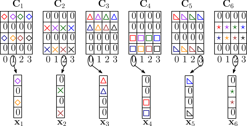
Fig. 2 represents a SCMA system with and , resulting in an overloading factor . For each th user, a dimensional codebook is defined as . Each codeword, , contains non-zero complex elements (). From the assigned codebook , data bits are directly mapped to a -dimensional codeword. The -dimensional codeword is defined as . Data from all users are SCMA encoded, which means that each symbol is mapped to the respective codeword (codebook columns).
The th () user’s received signal for a downlink system is represented as
| (2) |
where, diagonal channel matrix , is generated by placing the elements of the vector along the main diagonal of the matrix, , and is a complex additive white Gaussian noise (AWGN) vector.
II-B RSMA
Fig. 3 illustrates a multiple-input single-output (MISO) RSMA downlink system for users, showing the transmitter and SIC-based receiver for a downlink communication system. RSMA works by splitting the data of each user into a common message shared by multiple users and a private message intended for a specific user. The common message stream is formed by combining all or some users’ messages by the message combiner. The common message stream is intended to be decoded by all users, while private messages are individually decoded by the specific users they are intended for. The encoded common and private symbols are superimposed at the transmitter and are then transmitted through a wireless channel. The base station (BS) splits the stream of binary data stream into common and private messages. The common message is decoded by all users, but a specific user decodes the private message only after the common message has been decoded. Although the common message contains information relevant to all or some users, the data is not compromised because RSMA operates at the physical layer of communication, while data encryption and sharing occur at higher levels of the communication system.
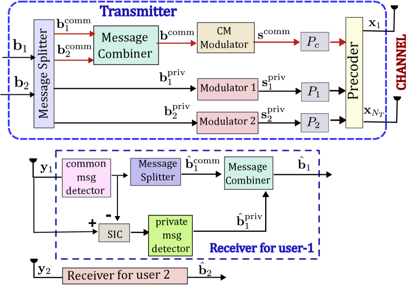
The two users’ messages are denoted by . These messages are split into common message streams and private message streams , respectively. For each channel use, the common message symbols from the individual users, and , are concatenated into a single common message vector . The common message is modulated and is denoted as . Similarly, private messages are individually modulated as . In RSMA, for each channel use, and the two modulated private streams are superimposed and transmitted through antennas. The transmitted signal of the RSMA system is given by [5]
| (3) |
where, . In (3), , , and represent the unit-norm precoder vectors, while , , and denote the power allocated to the common and private messages, respectively. If an SIC-based receiver is used, higher power is allocated to the common message because it is decoded first, followed by SIC to decode the private messages for each user [5]. The signal received at the th receiver () is given by
where channel vector, and represents the AWGN component. After receiving the signal, the th user decodes the common message. The message splitter then collects the common message specific to the th user, denoted as . SIC is then applied by subtracting the decoded common message of all users from the received signal, while accounting for the channel effects and the power allocated to the common message. Subsequently the private message for the th user is detected. Finally, the estimated common and private messages are combined to form the final estimated message for the user.
III Proposed RS-SCMA System Model
Our proposed RS-SCMA system model combines rate-splitting and SCMA techniques to enhance system performance. We first commence with the description of the RS-SCMA system with an uncoded architecture. Afterwards, the LDPC-coded RS-SCMA is explored. Throughout this work, we have considered a downlink communication scenario.
III-A Uncoded RS-SCMA
The proposed uncoded RS-SCMA system, illustrated in Fig. 4, details the transmitter and receiver architecture that integrates RSMA with SCMA. In this framework, the transmitter employs rate splitting to divide each user’s message into a common part and a private part, which are then superimposed for transmission. The common message stream, designed to be decoded by all users, is created by concatenating the common message components of all or selected users’ messages, while the private parts remain specific to each user.
To enable efficient resource utilization, SCMA encoding and detection are seamlessly integrated with RSMA, resulting in a hybrid RS-SCMA system. This system supports users over shared resources, where enables non-orthogonal transmission. Each user’s message is split into a common part and a private part, which are processed as follows:
-
•
The common message stream is modulated using QPSK
-
•
The private message streams are encoded using SCMA.
In the proposed RS-SCMA downlink communication system, the BS generates symbols for each user. The symbol stream for the th user is represented as . To ensure dimensional compatibility, the messages for the first users are split as common and private streams, and the remaining users’ are transmitted as private messages. The common messages are modulated by QPSK, while the private messages are SCMA encoded over the same resources. The common message streams are concatenated vertically and represented as . The private message streams are given by where the first private messages result from the splitting of message streams of users, while the remaining private messages are obtained fully from the remaining users’ whole messages. The system applies QPSK modulation to to obtain the modulated signal . On the other hand, SCMA maps the users’ data over resources to generate , each a complex vector of dimension.
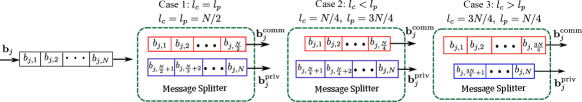
The message split operation is shown in Fig. 5. It illustrates the message splitting for the th user to common and private message streams with equal splitting and unequal splitting of the message stream. The allocation of symbols into common and private message streams can be generalized by introducing a splitting parameter , which represents the portion of symbols assigned as the common message stream and private message stream of the total number of generated symbols. Let and be the lengths of the private and common message stream, respectively. Using a splitting parameter , and can be better understood. We have taken and such that and are never fractions but only give whole numbers in . and can be expressed in terms of and as:
| (4) |
where .
Special Cases
-
•
Equal Splitting: For , the symbols are equally split:
-
•
Unequal Splitting: For unequal split, determines the relative proportions:
-
–
If , then , indicating that more symbols are allocated to the private stream.
-
–
If , then , indicating that more symbols are allocated to the common stream.
-
–
The above two cases are shown in Fig. 5 with different values of . This formulation offers flexibility in symbol allocation, adapting to system requirements. It accommodates scenarios where private streams predominate or common streams take precedence . The splitting parameter acts as a tunable design variable, balancing the distribution of common and private messages to meet specific communication objectives. The QPSK-modulated common messages are then superimposed with SCMA-encoded private messages over the same resources. The superimposed transmitted signal can be expressed as
| (5) |
where and represent the power allocation factors for the common and private message parts, respectively. The value of is greater than because the common message part is decoded first at the receiver.
The received signal for the th user is represented as
| (6) |
where , represents the channel vector from the transmitter to user , and represents the AWGN for the th user. The receiver starts the detection of the messages, and the details of the receiver shown in Fig. 4 are discussed next.
III-A1 Receiver 1 (Rx-1): Soft SIC-Based Architecture
-
(a)
QPSK demodulation: The received vector is equalized using zero-forcing (ZF) equalization that is denoted as . The log-likelihood ratios (LLRs) of the received bits are computed to form a LLR matrix. The Gray-coded constellation points are denoted as . Let denote the th element of the equalized signal . For simplicity, the subscript will be dropped from and denoted as , assuming that all calculations are performed for the th user. The squared Euclidean distance between and each constellation point is expressed as:
(7) The hard values are calculated from the Euclidean distance, which detects the common symbol as and is later fed to the message combiner. In addition to this, is used for the further calculation of the LLRs [29]. The LLR for the most significant bit (MSB) and the least significant bit (LSB) for th received symbols are given as:
(8) (9) In QPSK demodulation, (7) is used to obtain hard values for detecting the common message, while (8) and (9) are employed to calculate the LLRs. These LLRs provide the soft bit values utilized in soft SIC.
-
(b)
Soft symbols generation: The probabilities for each bit being 0 or 1 are derived from the LLR values of the received symbol as follows:
The probabilities of each QPSK constellation point are computed as:
The th soft symbol for the th user denoted by is computed as a weighted sum of the QPSK constellation points , based on the probabilities as
Then we form the vector .
-
(c)
Soft SIC: The soft symbol is multiplied with the power factor and the channel. The resulting signal is subtracted from the received signal as part of the soft SIC process to mitigate interference as
(10) -
(d)
SCMA detection: The residual signal is passed through an MPA-based SCMA detector to obtain the estimate of the private messages for the th user.
-
(e)
Message combiner: Finally, the estimated common message bits and private message bits are combined to reconstruct the complete message for the th user.
III-B LDPC-coded RS-SCMA
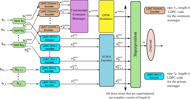
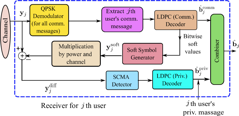
Fig. 6 shows the transmitter for LDPC-coded RS-SCMA with users and resources. The first users’ messages are split into common and private message streams as ( ; ) , , ( ; ). The rest of the users’ messages are transmitted as private messages. These bit streams are considered as row vectors. The message splitting in this case will not be similar to that in the uncoded RS-SCMA case. Each private and common message is LDPC coded, and the LDPC block length and code rate determine the number of information bits. Let the parameters be defined as follows:
-
•
: LDPC block length (total number of coded bits),
-
•
: Rate of LDPC coding for private messages,
-
•
: Rate of LDPC coding for common messages,
-
•
: Number of information bits per private message, and
-
•
: Number of information bits per common message.
The number of information bits for a single private message and a single common message can be expressed as:
For private messages and common messages, the total number of information bits is given by:
| Total private information bits | |||
| Total common information bits |
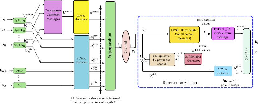
represents the common message bits for users as a whole. Similarly, represent the private message bits of users, each of length . After splitting, the common and private message blocks of each user are passed through the respective LDPC encoders, resulting in and . For each channel use, 2 bits from are collected for all users resulting in matrix of bits. Each LDPC-coded private message stream aggregates 2 bits from each of the users, resulting in a matrix. is QPSK modulated, resulting in which a complex vector. The private bits are SCMA encoded over resources, resulting in number of complex vectors: . For each channel use, the QPSK modulated common message vector is superimposed with number of SCMA encoded complex codewords. The transmitted signal is given by (5) and the signal received is given by (6).
In this section, a novel receiver architecture is analyzed, different from the receiver architecture utilized in uncoded RS-SCMA systems. This subsection introduces the receiver architecture as an integral component of the LDPC decoding process. Note that the Rx-1 architecture, proposed in Section III-A, is compatible with LDPC-coded RS-SCMA. In Rx-1, soft bits are obtained by tapping the signal after the QPSK demodulator, enabling the soft SIC to extract private messages. An alternative architecture, Rx-2, is proposed and illustrated in Fig. 7 to improve message detection for coded RS-SCMA systems. The primary distinction between Rx-1 and Rx-2 lies in the source from which the soft bits are taken for the soft SIC. In Rx-1, for the coded LDPC scenario, the LLRs of the bits are derived from the QPSK demodulator and subsequently passed to the soft symbol creator block. These LLRs are converted into soft symbols and utilized for soft SIC, facilitating the extraction of private message bits. Following this, both common and private message blocks are decoded using respective LDPC decoders. In contrast, in Rx-2, the input to the soft symbol creator block is sourced from the LLRs obtained through the LDPC common message decoder. These LLRs are then transformed into soft symbols for soft SIC, followed by SCMA detection and private message LDPC decoding to recover private messages. The proposed architecture leverages the LDPC decoder to enhance the accuracy of message reconstruction, even in the presence of noise and interference. In this design, the tapping for soft SIC is performed after the LDPC decoder, in contrast to Rx-1, where the tapping occurs after the QPSK demodulator. In both receiver architectures, the detection process begins once all transmitted messages, comprising parity and information bits, are received. The signal processing steps for the receiver of the LDPC-coded RS-SCMA (i.e., Rx-2) system is explained in detail below.
III-B1 Receiver 2 (Rx-2) Soft SIC with soft bits taken from the LDPC decoder output (Refer to Fig. 7)
-
(a)
QPSK demodulation and LLR calculation: The LLRs of the bits are calculated as part of the QPSK demodulation from the received signal after ZF equalization. It obtains the common message (information plus parity bits’ LLRs) for the th user. The LLRs are calculated similarly to that discussed for Rx-1. Note that the QPSK demodulator sends only the soft values (i.e., LLRs) to the LDPC decoder; no hard decisions are made by the QPSK demodulator.
-
(b)
LDPC decoding for common messages: The LLRs from the QPSK demodulator are given as input to the LDPC (Comm.) decoder. The LDPC (Comm.) decoder gives the LLRs of both message bits and parity bits for the common message block. These soft bits (LLRs) are given as input to the soft symbol generator block.
-
(c)
Soft symbol generator: The soft symbol generator converts the soft bits to soft symbols (the details of the conversion are given in Rx-1 discussion). Soft symbols are represented as . Moreover, the hard-decoded common message bits are fed to the message combiner block.
-
(d)
Soft-SIC: The output of the soft symbol generator block is multiplied by the power factor and the channel coefficient, resulting in . It is subtracted from the received signal as given by
(11) -
(e)
SCMA detection: The SCMA detector takes as input and performs MPA-based detection to compute the private message LLRs for all users.
-
(f)
LDPC Decoding: After completing soft SIC, the recovered message and parity bits are processed by the LDPC (Priv.) decoder to extract the private message bits, denoted as .
-
(g)
Combining common and private message bits: Finally, the decoded common message bits and private message bits are combined to reconstruct the complete message of the th user.
Remark 1: A trial was conducted in which both common and private messages are encoded and detected by SCMA. However, this approach increases system complexity. Since each symbol is represented by a codeword, separating the common message and performing SIC to retrieve the private message becomes challenging, especially when codewords from the same or different codebooks are superimposed and transmitted.
Remark 2: Another approach explored involved using SCMA mapping for the common messages while applying QPSK modulation to the private messages. However, this method significantly increased system complexity. Specifically, the MPA detection had to be performed twice for each user: first, to decode the common message, and then again during SIC for remodulation. This double detection process further compounded the overall complexity.
III-C Overloading factor analysis
In RS-SCMA, common and private messages are superimposed and transmitted over the same resources. Therefore, the overloading factor is expressed as:
The overloading factor in the proposed RS-SCMA system is tunable depending on the lengths and , which represent the number of symbols allocated to the common and private message streams, respectively. As the lengths of the common and private message streams vary, the system adjusts the overloading factor accordingly.
Consider an RS-SCMA system with users and resources. Let and denote the number of private and common symbols transmitted by all the users per channel use or transmission. If , the system operates in two phases, otherwise only the first phase is sufficient. These two phases are explained in the following.
III-C1 Phase 1: Overloaded Transmission of Common and Private Symbols
In the first phase, the system transmits common symbols and private symbols over resources for transmissions. The overloading factor for this phase is given by:
| (12) |
III-C2 Phase 2: Overloaded Transmission of Dominant Symbol Type
In the second phase, the system transmits only the dominant symbol type for transmissions:
-
•
If , private symbols are transmitted over resources, resulting in:
(13) -
•
If , common symbols are transmitted over resources, resulting in:
(14)
| (18) |
In particular, is equal to if (i.e., ), and equal to if (i.e., ).
The expressions for the overall overloading factor for the RS-SCMA can be derived from the above-discussed two phases as given below:
| (15) |
In (15):
-
•
is the overloading factor for Phase 1, where common symbols and private symbols are transmitted.
-
•
is the overloading factor for Phase 2, where either private symbols (when ) or common symbols (when ) are transmitted.
-
•
The total number of symbols transmitted in each phase is determined by the lengths of the corresponding message streams: for Phase 1 and for Phase 2.
The expression for the effective overloading factor can be derived by considering the two cases as given below:
Case-1: When , (i.e., )
| (16) | ||||
Case-2: When , (i.e., ):
| (17) | ||||
Consequently, the overall overloading factor can be calculated. From (16) and (17), the overloading factor can generally be expressed as given in (18) at the bottom of this page.
Example 1.
Overloading Factor Calculation: Let us take an example for Case-2, where (that is, and ). Here, represents the total number of symbols generated for each user. Consider a baseline SCMA system with and . Of six users, for the first four users, the messages are divided into streams of common message symbols of length and streams of private message symbols of length . For the remaining two users, the messages are transmitted only as private message symbols, with the same length as . Initially, the system transmits common message symbols and private message symbols over resources. This results in a total of transmitted symbols, yielding an overloading factor of during Phase 1. During Phase 2, the system behaves as an SCMA system, where only private symbols are transmitted over resources, resulting in an overloading factor of .
To summarize, the transmission is divided into two phases:
-
•
Phase 1: For channel uses, the system transmits common symbols and private symbols over resources. This results in an overloading factor of:
-
•
Phase 2: For channel uses, the system behaves like an SCMA system. During this phase, private symbols are transmitted over resources, resulting in an overloading factor of:
Overall Overloading Factor: The overall overloading factor for , is calculated using (17):
∎
III-D Complexity Analysis
The complexity of an SCMA receiver is per resource node, where denotes the number of codewords of each codebook, and represents the degree of the resource node. Consequently, the total complexity over resource nodes is .
In the proposed RS-SCMA system, the receiver complexity involves decoding both the common and private messages. The steps are as follows:
-
•
For QPSK-demodulation of common messages over resources, the complexity is .
-
•
The complexity of SIC is linear with the number of users, given as , since it involves subtracting the decoded common signal for each user.
Thus, the total receiver complexity of the RS-SCMA system is . This is slightly higher than the complexity of the standalone SCMA system. The ratio of the complexities is given by:
| (19) |
For , this ratio simplifies to
| (20) |
assuming a typical SCMA system with . This indicates the complexity increase of approximately compared to a standalone SCMA system. But this slight increase in complexity is offset by the improved overloading factor. While a standalone SCMA system with users and resources has an overloading factor of , the RS-SCMA system with the same configuration achieves an overloading factor of . For a standalone SCMA system with as given in (21), the value of , for with , so that the ratio in (20) becomes . It shows that the RS-SCMA system surpasses the SCMA system with the same overloading factor in terms of complexity.
The Rx-1 and Rx-2 receivers for LDPC-coded RS-SCMA differ in architecture based on where the LLRs of bits are collected for the soft-SIC. For QPSK demdulation, the complexity for resources and symbols is . For users, the soft symbol creator and SIC have a complexity of . LDPC decoding uses iterative algorithms, such as the belief propagation (BP) algorithm. The complexity is expressed as for common message decoder and for private message decoder, where is the number of decoding iterations, , represents the block length of private and common message, respectively and is the number of non-zero elements per column in the parity-check matrix. The complexity of the LDPC-coded Rx-1 and Rx-2 receivers are the same, however, Rx-2 offers lower BER, hence improved error performance, as detailed in Section IV. The complexity analysis for the coded RS-SCMA receivers is summarized in TABLE I.
| Component | Rx-1/Rx-2 () |
|---|---|
| QPSK Demodulation | |
| Soft Bits Computation | |
| Soft Symbols Generation | |
| SIC | |
| SCMA Detection | |
| LDPC Decoding (Common Messages) | |
| LDPC Decoding (Private Messages) | |
| Total |
IV Simulation Results
In this section, the average error-rate performance of the proposed RS-SCMA system for the downlink is evaluated and compared to the conventional SCMA and RSMA systems. All simulations are carried out using MATLAB-2023b and later versions. The error rate analysis considers users and resources for the RS-SCMA configuration, with 5G-NR-based LDPC codes [30]. Power allocation for common and private messages is based on the max-min fairness (MMF) power allocation scheme [31], which allocates power according to the user’s common and private message requirements, depending on the varying SNR. Using MMF, the power allocation factor at 0 dB , at 5 dB , at 15 dB , at 10 dB , at 20 dB , at 25 dB , and at 30 dB are taken. The maximum overloading factor for the proposed architecture with users and resources is . For a fair comparison, a overloaded SCMA system with users and resources is designed using differential evolution [32]. The overloaded SCMA codebook is designed with the following indicator matrix:
| (21) |
The simulation results are divided into two subsections: one presents the BER plots for an uncoded RS-SCMA system, and the other compares block-error error rate (BLER) for different overloading factors, using LDPC-coded RS-SCMA, for the proposed architecture alongside existing SCMA and RSMA systems. As calculated in (18), the overloading factor for the proposed RS-SCMA with is under the condition of equal split or . Additional analysis is also provided for an RS-SCMA system with an overloading factor of , where the number of users is and the resources are with the SCMA codebook taken from [23]. The simulation results for the MISO-RSMA system are presented for a scenario involving users transmitting over antennas. In this 2-user MISO-RSMA configuration, each user transmits two bit streams. By equally splitting these streams, a common message of 2 bits is formed, along with two private streams, each carrying 1 bit. For modulation, 4-PAM is applied to the common message, while BPSK is used to modulate the private messages for both users. The precoders are designed according to the method outlined in [33]. The superimposed signal is subsequently transmitted over the two antennas. Unless otherwise specified, all simulations are conducted in a Rayleigh fading channel environment.
IV-A BER performance analysis of uncoded RS-SCMA
Fig. 8 presents a comparison of BER and symbol error rate (SER) plot for hard SIC and soft SIC under RS-SCMA simulations with an equal splitting of common and private symbols (). It is evident that soft SIC provides a lower error rate as compared to hard SIC. Consequently, the remaining simulations for uncoded RS-SCMA use soft SIC.
Next, the error performance in terms of SER and BER for our proposed RS-SCMA with two different overloading factors is shown in Fig. 9. The overloading factors for RS-SCMA are () and , (). For configuration, 5 users split their messages into 5 common messages and 5 private messages, while the other 5 users send messages as only private messages. As shown in Fig. 9, RS-SCMA with performs better than that with . At BER , there is a gain of 4.4354 dB of the RS-SCMA with over that with . To maintain a consistency, rest of the results are given in terms of BER.
Fig. 10 and Fig. 11 demonstrate the BER performance of the proposed RS-SCMA system for varying lengths of and . In Fig. 10, the split factor satisfies , indicating that more symbols are allocated as private symbols (). In contrast, Fig. 11 corresponds to , where more symbols are allocated as common message streams (). The performance is evaluated in terms of overloading factor and BER by varying the lengths and . Fig. 10 and Fig. 11 show that as the overloading factor increases, more users share the same transmission resources, leading to increased interference among signals and therefore a higher BER. When the split factor decreases, increases, and the system behaves more like an SCMA system. As the overloading factor increases, the BER tends to rise, highlighting a trade-off between the overloading factor and performance.
As increases, the interference from common messages decreases, and the MPA detector, being robust, detects private symbols more efficiently. For cases with , such as (), where , the interference from common messages is relatively low, resulting in lower BER value. This improvement occurs because the system increasingly resembles an SCMA system as grows. Systems with exhibit higher overloading factors compared to , leading to relatively higher BER.
Similarly, for Fig. 11, as increases, more common symbols are allocated. For example, the system with has and consequently a higher BER. In contrast, systems with have reduced overloading factors (183% and 135%, respectively), leading to improved BER performance. It can be seen that as , the overloading factor decreases and the BER performance improves. For , observe that the BER performance improves as increases. This occurs because a higher reduces the need for SIC, minimizes error propagation, and allows more reliable detection of both common and private messages. Furthermore, systems with lower experience less interference from private symbols, further enhancing overall performance. Therefore, while a higher overloading factor allows for more efficient resource utilization, it also increases the risk of interference, impacting BER.
The explanation for the relationship between BER and the overloading factor can be better understood through Fig. 12. It shows the plot of BER against . The value of is fixed at 30 dB, and is varied. At , the system behaves as an SCMA system as all symbols are allocated as private symbols. At , the system reduces to an OMA system. This figure demonstrates that the overloading factor is tunable in the range of to . It can be observed that as the overloading factor increases, interference among the common and private symbols becomes more prominent, leading to a rise in BER. When is varied between 0 and 0.5, the overloading factor increases from, the overloading factor increases from to its highest value of , resulting in a corresponding increase in BER. However, when the value of is increased above 0.5 till 1, the overloading factor decreases from to , thus the system acts as an OMA system. The highest overloading factor is obtained at the equal split .The BER is the lowest for the , () i.e. for the SCMA system, but the overloading factor reduces to . For , then and all symbols are allocated as common symbols, meaning the system behaves as an OMA system. The BER performance is expected to be lowest at but it gives a higher BER value. It happens as the system is an OMA system where the symbols are represented as scalar values unlike SCMA or RS-SCMA system, where the multidimensional SCMA codewords and robust message detection through MPA helps in improved BER.
The average BER performance of the RS-SCMA system is compared with the conventional QPSK, RSMA, and SCMA systems in Fig. 13. In scenarios where all users transmit only common messages, the system exhibits behavior analogous to a standard QPSK system, representing an OMA configuration. Conversely, when all messages are private, the system operates similarly to an SCMA scheme with an overloading factor of . Both RS-SCMA and SCMA systems utilize multidimensional codebooks, whereas the OMA system employs a scalar QPSK constellation. The multidimensional structure of RS-SCMA and SCMA, combined with the efficient detection provided by the MPA, enhances error resilience and signal detection, outperforming the OMA system. The RS-SCMA system achieves its maximum overloading factor of when the message is equally split between common and private components. Adjusting the splitting parameter directly influences the overall system overloading factor and subsequently impacts the error-rate performance, as illustrated in Fig. 13 and this observation is consistent with earlier results.
IV-B BLER performance analysis of LDPC-coded RS-SCMA system
In this section, simulation results are presented for the LDPC-coded RS-SCMA system, whereby the common and private messages are equally split. For all simulations, the block length for common and private messages is . The code-rates for common and private messages are denoted as and , respectively.
Fig. 14 illustrates the BLER performance of the LDPC-coded receivers, Rx-1 and Rx-2. Rx-2 demonstrates a more accurate estimation of the common message stream compared to Rx-1. In Rx-2, soft bits are derived from the LDPC decoder output, offering enhanced protection for common message bits and effectively reducing error propagation in the soft-SIC process. This improvement significantly enhances the detection accuracy of private message bits. We consider for both AWGN and Rayleigh fading channels. For an AWGN channel at BLER= , there is a gain of 0.541 dB for Rx-1 over Rx-2. For a fading channel, Rx-2 has a coding gain of 0.839 dB over Rx-1 at BLER= .
Fig. 15 presents the BLER performance for LDPC-coded SCMA, RSMA, and the proposed RS-SCMA architectures. The coding rates for SCMA and RSMA are taken , and for RS-SCMA (). Despite RSMA having a lower overloading factor, the SCMA system demonstrates better performance, attributed to its multi-dimensional vector codebook and MPA decoding. The RS-SCMA system with Rx-2 gives the lowest BLER that shows improved error performance among the four systems.
The BLER performance of the LDPC coded RS-SCMA system for Rx-2, with different LDPC code rates for common and private message blocks, is presented in Fig. 16. Observe that the system with for the common message and for the private message achieves a lower BLER performance than the other configurations. Lower code rate LDPC codes generally provide enhanced error correction capabilities compared to the ones wiht higher code rates. In the case of SCMA, each symbol corresponds to a vector codeword, whereas in QPSK, it is represented as a scalar. SCMA detection utilizes the robust MPA, ensuring reliable error performance even at higher data rates. Therefore, the configuration with () shows slightly better performance compared to (). The plot for () gives the highest BLER compared to the rest for the aforementioned reasons. Since QPSK requires greater error protection compared to SCMA, it is advisable to allocate a lower code rate to QPSK (that is, the common message part).
V Conclusion
This paper presents the first novel hybrid architecture called RS-SCMA that integrates RSMA with SCMA. The transceiver for RS-SCMA employs QPSK modulation for common messages and SCMA mapping for private messages. Two receiver architectures, designated as Rx-1 and Rx-2, are proposed. The Rx-2 receiver achieves improved signal quality by mitigating error propagation in the soft-SIC process, resulting in a lower BER compared to Rx-1. Performance evaluation reveals that the RS-SCMA system surpasses the SCMA system with the same overloading factor, delivering superior BER performance with a minimal increase in complexity. In addition, the system offers a tunable overloading factor by adjusting the message-splitting factor. The comparative analysis, conducted with and without the incorporation of LDPC error-correcting codes, underscores the robustness of the proposed approach. In particular, the RS-SCMA system demonstrates substantial improvements in error rate performance for equivalent overloading factors, outperforming conventional SCMA and RSMA systems.
References
- [1] C. X. Wang, X. You, X. Gao, X. Zhu, Z. Li, C. Zhang, H. Wang, Y. Huang, Y. Chen, H. Haas, J. S. Thompson, E. G. Larsson, M. D. Renzo, W. Tong, P. Zhu, X. Shen, H. V. Poor, and L. Hanzo, “On the Road to 6G: Visions, Requirements, Key Technologies, and Testbeds,” IEEE Commun. Surv. & Tut., vol. 25, no. 2, pp. 905–974, 2023.
- [2] Z. Zhang, Y. Xiao, Z. Ma, M. Xiao, Z. Ding, X. Lei, G. K. Karagiannidis, and P. Fan, “6G Wireless Networks: Vision, Requirements, Architecture, and Key Technology,” IEEE Veh. Technol. Mag., vol. 14, no. 3, pp. 28–41, 2019.
- [3] E. K. Hong, I. Lee, B. Shim, Y. C. Ko, S. H. Kim, S. Pack, K. Lee, S. Kim, J. H. Kim, Y. Shin, Y. Kim, and H. Jung, “6G R&D vision: Requirements and Candidate Technologies,” J. of Commun. and Netw., vol. 24, no. 2, pp. 232–245, 2022.
- [4] Y. Liu, X. Yuan, Z. Xiong, J. Kang, X. Wang, and D. Niyato, “Federated Learning for 6G Communication: Challenges, Methods, and Future Directions,” China Commun., vol. 17, no. 9, pp. 105–118, 2020.
- [5] Y. Mao, O. Dizdar, B. Clerckx, R. Schober, P. Popovski, and H. V. Poor, “Rate-Splitting Multiple Access: Fundamentals, Survey, and Future Research Trends,” IEEE Commun. Surv. & Tut., vol. 24, no. 4, pp. 2073–2126, 2022.
- [6] H. Chen, D. Mi, T. Wang, Z. Chu, Y. Xu, D. He, and P. Xiao, “Rate-Splitting for Multicarrier Multigroup Multicast: Precoder Design and Error Performance,” IEEE Trans. on Broadcast., vol. 67, no. 3, pp. 619–630, 2021.
- [7] B. Rimoldi and R. Urbanke, “A Rate-Splitting Approach to the Gaussian Multiple-Access Channel,” IEEE Trans. on Inf. Theory, vol. 42, no. 2, pp. 364–375, 1996.
- [8] A. Grant, B. Rimoldi, R. Urbanke, and P. Whiting, “Rate-Splitting Multiple Access for Discrete Memoryless Channels,” IEEE Trans. on Inf. Theory, vol. 47, no. 3, pp. 873–890, 2001.
- [9] O. Dizdar, Y. Mao, W. Han, and B. Clerckx, “Rate-Splitting Multiple Access for Downlink Multi-Antenna Communications: Physical Layer Design and Link-level Simulations,” in 2020 IEEE 31st Annu. Int. Symp. on Pers., Indoor and Mobile Radio Commun., 2020, pp. 1–6.
- [10] H. Chen, D. Mi, Z. Chu, P. Xiao, Y. Xu, and D. He, “Link-Level Performance of Rate-Splitting based Downlink Multiuser MISO Systems,” in 2020 IEEE 31st Annu. Int. Symp. on Pers., Indoor and Mobile Radio Commun., Aug 2020, pp. 1–5.
- [11] S. Zhang, B. Clerckx, D. Vargas, O. Haffenden, and A. Murphy, “Rate-splitting multiple access: Finite constellations, receiver design, and SIC-free implementation,” IEEE Trans. on Commun., vol. 72, no. 9, pp. 5319–5333, 2024.
- [12] H. Chen, D. Mi, Z. Liu, P. Xiao, and R. Tafazolli, “Rate-Splitting for Overloaded Multigroup Multicast: Error Performance Evaluation,” in 2020 IEEE Int. Conf. on Commun. Workshops (ICC Workshops), 2020, pp. 1–6.
- [13] D. Mi, H. Chen, Z. Chu, P. Xiao, Y. Wu, and C. L. Wang, “Rate-Splitting Multiple Access With Finite-Alphabet Constellations: Precoder Optimization and Achievable Rate Performances,” IEEE Trans. on Green Commun. and Netw., vol. 8, no. 4, pp. 1293–1307, 2024.
- [14] M. M. Sahin, O. Dizdar, B. Clerckx, and H. Arslan, “OFDM-RSMA: Robust Transmission under Inter-Carrier Interference,” IEEE Trans. on Commun., vol. PP, no. PP, pp. 1–13, 2024.
- [15] Z. Liu and L.-L. Yang, “Sparse or Dense: A Comparative Study of Code-Domain NOMA Systems,” IEEE Trans. Commun., no. 8, pp. 4768–4780, Aug 2021.
- [16] H. Nikopour and H. Baligh, “Sparse Code Multiple Access,” in 2013 IEEE 24th Annu. Int. Symp. on Pers., Indoor, and Mobile Radio Commun. (PIMRC), 2013, pp. 332–336.
- [17] M. Taherzadeh, H. Nikopour, A. Bayesteh, and H. Baligh, “SCMA Codebook Design,” in 2014 IEEE 80th Veh. Technol. Conf. (VTC2014-Fall), 2014, pp. 1–5.
- [18] S. Zhang, K. Xiao, B. Xiao, Z. Chen, B. Xia, D. Chen, and S. Ma, “A Capacity-based Codebook Design Method for Sparse Code Multiple Access Systems,” in 2016 8th Int. Conf. on Wireless Commun. & Signal Process. (WCSP), Oct 2016, pp. 1–5.
- [19] L. Yu, P. Fan, D. Cai, and Z. Ma, “Design and Analysis of SCMA Codebook based on Star-QAM Signaling Constellations,” IEEE Trans. Veh. Technol., no. 11, p. 10543–10553, Nov. 2018.
- [20] Z. Mheich, L. Wen, P. Xiao, and M. Amin, “Design of SCMA Codebooks based on Golden Angle Modulation,” IEEE Trans. Veh. Technol., no. 2, p. 1501–1509, Feb. 2018.
- [21] Y. Chen and J. Chen, “On the Design of Near-Optimal Sparse Code Multiple Access Codebooks,” IEEE Trans. Commun., no. 5, p. 2950–2962, May 2020.
- [22] Q. Luo, Z. Liu, G. Chen, P. Xiao, Y. Ma, and A. Maaref, “A Design of Low-Projection SCMA Codebooks for Ultra-Low Decoding Complexity in Downlink IoT Networks,” IEEE Trans. on Wireless Commun., vol. 22, no. 10, pp. 6608–6623, 2023.
- [23] X. Li, Z. Gao, Y. Gui, Z. Liu, P. Xiao, and L. Yu, “Design of Power-Imbalanced SCMA Codebook,” IEEE Trans. on Veh. Technol., vol. 71, no. 2, pp. 2140–2145, Feb 2022.
- [24] S. Chaturvedi, Z. Liu, V. A. Bohara, A. Srivastava, and P. Xiao, “A Tutorial on Decoding Techniques of Sparse Code Multiple Access,” IEEE Access, vol. 10, pp. 58 503–58 524, 2022.
- [25] L. Dai, B. Wang, Y. Yuan, S. Han, I. Chih lin, and Z. Wang, “Non-orthogonal Multiple Access for 5G: Solutions, Challenges, Opportunities, and Future Research Trends,” IEEE Commun. Mag., vol. 53, no. 9, pp. 74–81, 2015.
- [26] Z. Ding, X. Lei, G. K. Karagiannidis, R. Schober, J. Yuan, and V. K. Bhargava, “A Survey on Non-Orthogonal Multiple Access for 5G Networks: Research Challenges and Future Trends,” IEEE J. on Selected Areas in Commun., vol. 35, no. 10, pp. 2181–2195, 2017.
- [27] ——, “A Survey on Non-Orthogonal Multiple Access for 5G Networks: Research Challenges and Future Trends,” IEEE J. on Selected Areas in Commun., vol. 35, no. 10, pp. 2181–2195, 2017.
- [28] Q. Luo, P. Gao, Z. Liu, L. Xiao, Z. Mheich, P. Xiao, and A. Maaref, “An Error Rate Comparison of Power Domain Non-Orthogonal Multiple Access and Sparse Code Multiple Access,” IEEE Open J. of the Commun. Soc., vol. 2, pp. 500–511, 2021.
- [29] W.-J. Choi, K.-W. Cheong, and J. Cioffi, “Iterative Soft Interference Cancellation for Multiple Antenna Systems,” in 2000 IEEE Wireless Commun. and Netw. Conf. Conf. Rec. (Cat. No.00TH8540), vol. 1, 2000, pp. 304–309 vol.1.
- [30] T. Richardson and S. Kudekar, “Design of Low-Density Parity Check Codes for 5G New Radio,” IEEE Commun. Mag., vol. 56, no. 3, pp. 28–34, 2018.
- [31] A. Z. Yalcin, M. K. Cetin, and M. Yuksel, “Max-Min Fair Precoder Design and Power Allocation for MU-MIMO NOMA,” IEEE Trans. on Veh. Technol., vol. 70, no. 6, pp. 6217–6221, 2021.
- [32] K. Deka, M. Priyadarsini, S. Sharma, and B. Beferull-Lozano, “Design of SCMA codebooks using differential evolution,” in 2020 IEEE Int. Conf. on Commun. Workshops (ICC Workshops), June 2020, pp. 1–7.
- [33] Y. Mao, B. Clerckx, and V. O. Li, “Rate-Splitting Multiple Access for Downlink Communication Systems: Bridging, Generalizing, and Outperforming SDMA and NOMA,” J. of Wireless Commun. and Netw., vol. 2018, no. 133, 2018.