Back to the Figure-8 Stellarator
Abstract
The first stellarator design was a simple tube of plasma twisted and closed on itself in the form of a figure-8. The line of such devices, however, was quickly ended over concerns related to plasma stability. We revisit the figure-8 concept, re-imagined as a modern optimized stellarator, and find the potential for a high degree of stability, as well as exceptionally simple construction. In particular, the design that we find admits planar coils, and is the first quasi-isodynamic stellarator design to have this property. Our work is made possible by recent theoretical progress in the near-axis theory of quasi-isodynamic stellarators, combined with fundamental progress in the numerical solution of three-dimensional magnetohydrodynamic equilibria that cannot be well represented using traditional cylindrical coordinates.
1 Introduction
In 1951, on a ski trip to Aspen, Colorado, Lyman Spitzer had an idea for a device to achieve controlled thermonuclear fusion. The form he envisioned had the shape of a figure-8, an endless tube of plasma, bent around and closed onto itself. Although this idea was realized in a number of experiments during the following years [1, 2], it was decided that the figure-8 stellarator was unstable and that it would be better to switch over to stellarators that achieve rotation of magnetic field lines via helically wound coils [3], e.g. so-called classical stellarators. These, it was predicted, would be stabilized by magnetic shear, and were also expected to be easier to construct than the figure-8 because the plasma volume would have a simpler, more toroidal shape [4, 5].
Times have changed. The modern stellarator, which can be thought of as a descendant of the classical stellarator, is carefully sculpted using computational optimization techniques, resulting in shapes that are impressive to behold but hard to build. Furthermore, although stellarators can exhibit a high degree of stability, examples that are sufficiently well-optimized for plasma confinement tend to have fairly low magnetic shear, and owe their stability more to other properties such as the so-called “magnetic well”. Thus, the justifications for turning away from the figure-8 do not seem to apply anymore.
It might seem improbable that a design discarded long ago could possibly stand up against modern stellarators. Indeed, if the figure-8 were really a credible design, meeting the various requirements of a fusion device, why wouldn’t it naturally arise from stellarator optimization? A possible answer is that the figure-8, despite its relative simplicity, presents a technical challenge to investigate because its particular shape is not easily represented by the coordinates (cylindrical) that are at the heart of the equilibrium codes used for optimization. It seems reasonable to assume that such codes use these coordinates because they suited the kind of stellarators that were of interest at the time when the codes were being developed, and the resounding success of stellarator optimization left no compelling reason to doubt this choice.
However, methods developed in recent years to construct new stellarator designs, mostly based on near-axis theory, have attracted the attention of researchers to a broader range of stellarator shapes. Additionally, developers of recent stellarator equilibrium solvers [6, 7], aware of the potential fundamental limitations of arbitrarily fixed coordinates, built in capabilities to explore alternative choices. The time is right, we think, to revisit the figure-8.
In this paper, we make a first investigation of Spitzer’s figure-8, re-imagined as a modern quasi-isodynamic (QI) stellarator [8, 9, 10]. This is enabled by recent theoretical progress in the near-axis theory of QI stellarators [11, 12, 13, 14], as well as the extension of the three dimensional magnetohydrodynamic equilibrium solver GVEC to use flexible user-specified coordinates to handle virtually any shape around a closed space curve [15]. The present work therefore serves as a first demonstration of the potential for optimization of ‘exotic’ stellarator configurations, for which progress has so far been difficult or impossible. More extensive work will become possible as GVEC is integrated with stellarator optimization tools [16] and as other numerical tools are adapted to interface with it.
The paper is organized as follows. In section 2 we describe the near-axis method for constructing approximately QI configurations of the figure-8 type. This includes the shape of the magnetic axis, and the elliptical shaping of the magnetic surfaces. In section 3, we describe what makes the figure-8 special, key geometric measures and how they affect the properties of the first-order near-axis solutions. Section 4 describes the numerical optimization of a set of configurations for a vacuum magnetic well, to demonstrate the tendencies of the figure-8 to support magnetohydrodynamic stability. This section includes a discussion of the underlying geometric reasons for these tendencies, from the perspective of near-axis theory. In section 5, we turn attention to a single configuration to demonstrate compatibility with a simple planar coil set, after which we conclude with a general discussion.
2 Near-axis construction of a QI Figure-8 stellarator
Low-field-period () configurations, including those and examples with a figure-8 appearance, have arisen using the theory of the near-axis expansion (NAE) [11, 12, 17]. Such solutions can be “directly constructed” [18, 11] by evaluating the asymptotic description near the magnetic axis, at a specified distance (average minor radius). The resulting plasma boundary shape can be provided as input to a magnetohydrodynamic (MHD) equilibrium code like GVEC for further investigation.
Based on the methods described in [11, 13], we will perform this construction initially at first order in the expansion; to understand the issue of stability we will later make an analysis at second order (see Section 4.1).
2.1 Magnetic axis shape
The NAE for QI stellarators differs significantly from that for quasi-symmetric (QS) stellarators [19, 20, 21]. For QI, controlling the geometry of the magnetic axis curve to produce flattening points (points of zero curvature) is a significant first hurdle. We choose to obtain the magnetic axis curve by solving the Frenet-Serret equations [22, 23] providing the curvature, , and torsion, , as functions of the arc length along the curve,
| (1) |
where is the axis curve, and is its tangent. Not all functions and yield a closed curve, so optimization is required [24]. The method used here has been described elsewhere [25] and further technical details will be provided in a separate publication [13].
Because of the points of zero curvature that lie along the axis curves, the frame is not actually the conventionally defined Frenet frame, but the signed Frenet frame [11, 14, 26], defined to be continuous within a field period, i.e. , where is an integer. By our convention, field periods begin and end at locations of maximum field strength, which are also points of stellarator symmetry [27]. The signed Frenet frame is the same as the standard Frenet frame except that the normal and binormal vectors, and , are ‘corrected’ by a sign to ensure continuity at locations of minimum field strength where the axis curve can be said to undergo inflection; see details in Appendix A of [14] and a more general discussion of such frames in [26]. The magnetic axis curves considered here can be described by the following expressions for signed curvature and torsion
| (2) | |||
| (3) |
where , and are constants. The form of is chosen to fix the order of its zeros at the magnetic field extrema: at maxima and at minima. The signed Frenet frame is then obtained by integrating Eq. 1, substituting the above forms of and . Two of the three free constants are determined by iteratively solving the equations to satisfy the closure conditions.
The number of times the signed normal rotates about the axis is referred to as the axis helicity [28, 29, 14] (also self-linking number [30, 31, 32]) and we define the per-field-period helicity as . Fixing the length of the axis to be equal to , the helicity to be , and the field period number , we obtain a family of curves, which we parameterize by ; the other constants and are determined by the closure condition.
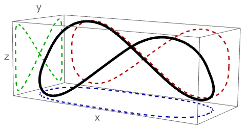
A special case is obtained in the limit , where the mean torsion is found to also be zero, ; note also in this case. This zero-torsion case is the planar figure-8 (a lemniscate [33]), in particular the following shape: ![[Uncaptioned image]](/html/2411.16411/assets/x1.png) . Because the axis is chosen to begin () along the positive axis, this curve lies entirely in the - plane and self-intersects at the origin.
. Because the axis is chosen to begin () along the positive axis, this curve lies entirely in the - plane and self-intersects at the origin.
The planar figure-8 curve is obviously not suitable for the magnetic axis of a stellarator due to its self intersection. The curve must be brought somewhat out of the - plane to open up space for the plasma volume to form around the magnetic axis (also coils, etc.), which can be achieved by varying the free parameter . To complete our solution to zeroth order in the NAE, the magnetic field strength dependence along the magnetic axis is chosen as
| (4) |
defined such that the mirror ratio is , and at field strength minima, e.g. , the latter to promote the formation of a magnetic well; see Section 4.1. With this defined, the conversion between axis length and Boozer toroidal angle may be made [18, 11]:
| (5) |
where is the zeroth-order poloidal current function.
2.2 Configuration shaping to first order
To complete the construction of the configuration to first order, in particular to determine the elliptical shape of the surfaces that form around the magnetic axis, we must solve the so-called ‘sigma equation’ [24], depending on several given inputs,
| (6) |
where and are functions of [11, 12], and is the rotational transform on axis; note we have assumed zero toroidal current. The solution to this equation determines the surface shape via the components of the first order coordinate mapping,
| (7) | |||||
| (8) |
which enters the coordinate mapping as follows
| (9) |
where .111This pseudo-radial coordinate differs by a factor of compared to some others [18, 14].
Because elongation (of the elliptical cross sections) is a particularly sensitive feature of QI configurations that are derived from NAE theory, we choose to solve the equation in a non-standard fashion [13], using elongation as input, instead of the function , which is used conventionally [34, 11]. The elongation of the elliptical cross section is
| (10) |
The “elongation profile” is set by the function , which for the class of configurations considered here is chosen to have the following form
| (11) |
where and are constants. Note that , where is defined in [35] as the angle subtended by a right angle triangle with the axes of the ellipse as catheti. Thus, a larger represents a larger elongation of cross sections, and the sign of gives growing (positive) or decreasing (negative) elongation away from the point of minimum field strength. A smooth version of is used for proper behavior at higher order NAE, as described in [14].
3 Defining features of a figure-8 QI stellarator
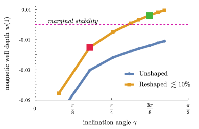
The overall geometry of a figure-8 stellarator can be thought intuitively of as a racetrack shape, bent out of the horizontal plane by inclining each end in opposite senses by an amount that we will call the “inclination angle”, , following Spitzer [4]. This angle is zero in the racetrack-limit, and must always be somewhat less than (the planar curve limit), to allow for sufficient space in the region where the node of the “8” appears. We will use the inclination angle as a simple way to quantify the degree to which a configuration approaches the ideal figure-8 shape, and use instead of to parameterize the class of axis curves introduced in the previous section.

Varying the inclination angle, we produce eight configurations, all with identical elongation and on-axis field strength . The elongation (versus ) varies from at to at (in particular and in Eqn. 11). A number of other characteristics of these configurations are provided in Table 1. One of those is a proxy for QI error [12], , which is observed to monotonically decrease with inclination angle, as observed previously [25]. This quantity is defined as the root-mean-square deviation of , as obtained from the equilibrium code, from the theoretical value predicted by first order near-axis theory ; see Sec. 4.
| 0.0786 | 0.1794 | 0.2538 | 0.3127 | 0.3385 | 0.3740 | 0.4012 | 0.4223 | |
| 0.3603 | 0.4905 | 0.5804 | 0.6585 | 0.6962 | 0.7529 | 0.8005 | 0.8398 | |
| 0.9066 | 0.8170 | 0.7144 | 0.6020 | 0.5420 | 0.4468 | 0.3637 | 0.2935 | |
| 0.0934 | 0.1830 | 0.2856 | 0.3980 | 0.4580 | 0.5532 | 0.6363 | 0.7065 | |
| 0.0304 | 0.0152 | 0.0122 | 0.0115 | 0.0115 | 0.0115 | 0.0113 | 0.0113 | |
| Axis | ||||||||
The inclination angle is a somewhat arbitrary measure, and unsatisfying from a theoretical perspective. To dig deeper we note a remarkable feature of the class of curves, defined to have total axis helicity . In the limit as approaches , the torsion tends to zero point-wise, implying that the axis normal manages to undergo a complete rotation without torsion. In the language of the mathematics of closed space curves (or more precisely ‘ribbons’), it can be said that such a curve generates its self-linking via writhe (mostly) instead of twist, the latter being the integrated torsion [30, 31, 32]. The contribution to self-linking from these two sources is expressed by the Călugăreanu-White-Fuller formula [32, 30],
| (12) |
whereby the writhe is formally defined. In this case we have defined the ribbon as the magnetic axis curve along with the signed normal vector; see Table 1 for values of and average torsion for the sequence of axis inclinations. Intuitively, curves with high writhe are naturally formed by elastic objects like rods or belts, to relieve internal twisting stresses while respecting self-linking, which is topologically constrained.
This suggests another way to identify a figure-8 stellarator (alternative to using the inclination angle), namely by the feature that the helicity (self-linking) of its magnetic axis largely achieved without torsion, i.e. it is a curve of large writhe. This property of the figure-8 has significant consequences for how the stellarator generates rotational transform [36, 37, 28], and for a number of other attractive properties of the configurations, as we will show in what follows.
According to near-axis formalism, the on-axis rotational transform can be related to helicity and torsion as a solubility condition of Eqn. 6,
| (13) |
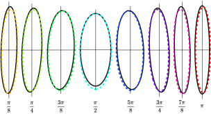
There is both explicit and implicit dependence on in this equation, as the function depends on . Indeed omnigenity (assuming stellarator symmetry) implies , which however cannot generally be satisfied for all because of the periodicity constraint [11, 12].222This reflects a more general conflict, beyond NAE, between omnigenity and periodicity at field maxima under the assumption of irrational [38]. In near-axis theory of QI the conflict is addressed by defining to control the violation of omnigenity [11, 12, 14]. However, in the limit as , noting the second factor of the integrand on the left-hand-side of Eq. 13 is positive-definite, we do find , and therefore by periodicity; the trend toward this solution can be observed in Table 1. Practically speaking, this means that as the figure-8 limit is approached, it becomes possible to satisfy the omnigenity condition more uniformly. Furthermore, low torsion favors low amplitude of the function obtained from Eq. 6, as has been noted before [12], which controls the tilt of the ellipses [35]. Therefore, in the figure-8, the ellipses stay closely aligned with the Frenet frame (see Fig. 4), which itself performs very little twist about the axis.
To summarize, the figure-8 is special in that it generates a relatively large rotational transform with little axis torsion. Using near-axis theory, a QI figure-8 can be constructed that, as a consequence of low torsion, has exceptionally weak shaping at first order. As we will find in the following sections, weak shaping also extends, in a particular sense, to higher order.
4 Susceptibility of the Figure-8 to the formation of a magnetic well
A first issue to investigate for the figure-8 is the question of stability, which was historically one of the main criticisms motivating the switch to classical stellarators. Stellarator optimization commonly uses proxies for linear stability [39]. Here we focus on the most basic one, the so-called magnetic well, [40, 41] with the plasma volume, which enters prominently in Mercier’s stability criterion for ideal-MHD interchange stability [42].
To explore the question of stability, we conduct a series of optimizations, based on the set of initial stellarator configurations, constructed with different levels of inclination as defined in the previous section. Optimization of the boundary shape is performed using new capabilities of the 3D equilibrium solver GVEC, employing coordinates based on a generalized Frenet frame [15]. The shape of the boundary is specified as an input by the components of a coordinate mapping, here initially calculated to first order. We are then able to provide a boundary shape as input to GVEC by modifying the boundary obtained from the NAE, i.e. with . Radial deformation of the first-order shape is thereby achieved by the function whose effect is to move the surface shape along the ‘radial’ direction defined by , as depicted in Fig. 2. The choice corresponds to the unshaped (elliptical) first-order solution; it is the choice that is used to compute the values of given in Table 1. To parameterize , a number of uniformly distributed but independent control points are defined in the - plane, taking stellarator symmetry and field-periodicity into account ( ranges from to and from to ).

The optimization space consists of the value of at the control points, and these values are bounded between and so as to limit the deformation to a maximum of . The number of control points is chosen ( in the direction and in the direction) to control ‘triangularity’ at several values of the toroidal angle, i.e. the shape freedom that arises at second order in the NAE, which is known to control the magnetic well [43, 35].
A total of eight optimizations are performed, corresponding to the cases presented in Table 1. By limiting the deformation size, global optimization (we use the Bayesian method in Mathematica) can be used to find the maximum of the target function, which is chosen to be the magnetic well depth (note that positive values indicate stability, opposite to the case for )
| (14) |
where is a normalized surface label related to the toroidal flux function, .
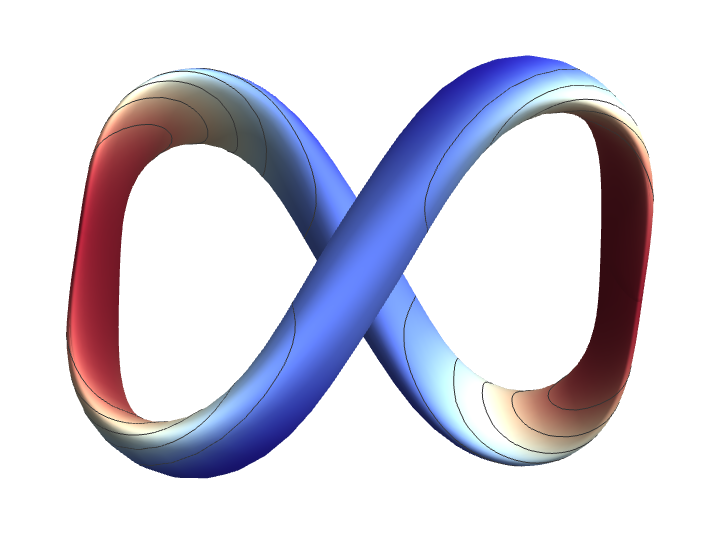
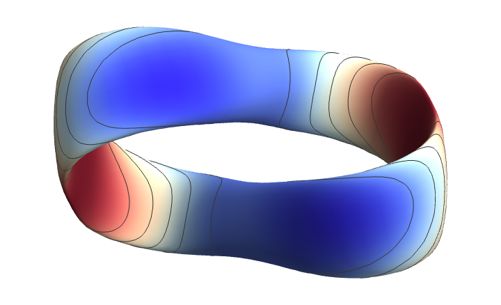
The result of these optimization runs is shown in Fig. 3. It is shown that the maximum achievable well depth is a monotonically increasing function of the inclination angle. Simultaneously the proxy for QI error is observed to monotonically decrease, as shown in Table 1. Note that the final boundary shapes resulting from the optimization are nearly indistinguishable visually from the initial elliptical shapes, as demonstrated for two extreme values of in Fig. 4.


4.1 Discussion of MHD stability
Practically speaking, the above results show by example that the figure-8 is compatible with a magnetic well, even especially so in some sense. While these results are encouraging, we would like to probe deeper to understand the reason for the observed tendency, and determine what can be said more generally about the stability of this type of stellarator.
We therefore turn back to near-axis theory, which provides information about the vacuum magnetic well at second order [43, 35], here expressed, assuming vacuum, as , recalling that indicates stability, i.e. outwardly growing magnetic pressure [40, 41].
Instead of explicitly constructing QI configurations at second order [14], which, depending on shaping choices, only provides similar anecdotal evidence as already shown above, we turn to more basic considerations. To see how the properties of the first-order construction (i.e. the “unshaped” configuration) can affect stability, we can examine the locations of zero curvature along the axis, where the field geometry resembles a straight mirror [14, 44]. Here the radial variation of , being constrained by the vacuum expression , with , is completely determined by first-order properties, and can be expressed to leading order near the magnetic axis as
| (15) |
where primes denote derivatives with respect to , the angled brackets an average over , and the other symbols have been defined in Sec. 2. This expression comes from Eqn. B4 of [44], assuming vacuum conditions, using at locations of stellarator symmetry, and re-expressed in terms of elongation (more precisely ) to be consistent with the approach to first-order construction used here; see Sec. 2.2. The three resulting terms within the bracket (note the signs) can be interpreted in the way depicted in Fig. 5.333This behavior is purely based on equilibrium considerations. The picture changes if, in addition to this, the field is required to satisfy omnigenity beyond first order, as discussed in [44]. These diagrams show three fundamental ways in which the geometry of the surface, through the curvature vector of field lines, affect the -average of .
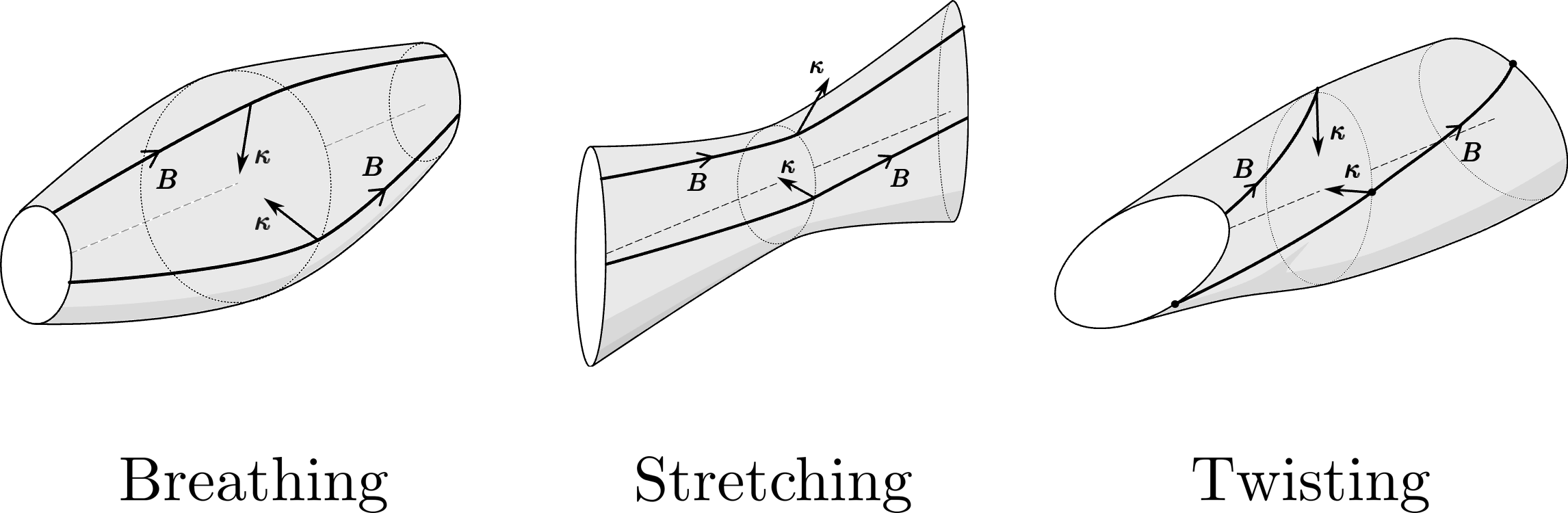
“Breathing” (first term) is the flux-preserving variation in cross-sectional areas due to variation of , which makes a destabilizing contribution at the field minimum, and stabilizing at the field maximum. To minimize its detrimental effect, (Eqn. 4) was chosen to be flat in the neighborhood of the minimum.
“Stretching” (second term) is the variation of elongation, measured here by , which on average favors stability when the elongation grows away from the inflection point, i.e. for as chosen in Sec. 2.2. This positive contribution is identical throughout the sequence of configurations in Section 3.
The remaining effect,“Twisting” (third term), is the destabilizing effect that axis torsion has via ellipse rotation. As discussed in Section 3, the reduction of twist, in exchange for increased writhe, is the key geometric feature distinguishing the magnetic axis of the figure-8, and here we find it is the key feature underlying the observed tendencies toward stability. In short, low level of twisting from axis torsion makes the figure-8 intrinsically more stable at field extrema, so that a relatively small amount of additional shaping elsewhere is needed to produce a global magnetic well.
5 A Quasi-Isodynamic Figure-8 Stellarator with Planar Coils
Historically speaking a second advantage (besides stability) that the classical stellarator was thought to have over the figure-8 was the relative simplicity of construction [5]. To address this issue in the context of modern stellarators, a key question is that of coil complexity. As a case study we therefore consider a single figure-8 configuration on which to perform coil optimization. This configuration, distinct from the ones of the previous section, has axis inclination , elongation ranging from approximately at the field maximum, to at the field minimum, , and a rotational transform at first order of .
The constructed boundary shape was re-optimized for a magnetic well as described in the previous section, resulting in a well depth . To show how the surfaces actually were deformed to achieve this, a set of cross sections at uniformly spaced values of are shown in Fig. 6. The simplicity of these cross sections, showing no visible hint of the expected “bean” shape, seem to have strong consequences on the coil set that is obtained during optimization, as presented below.

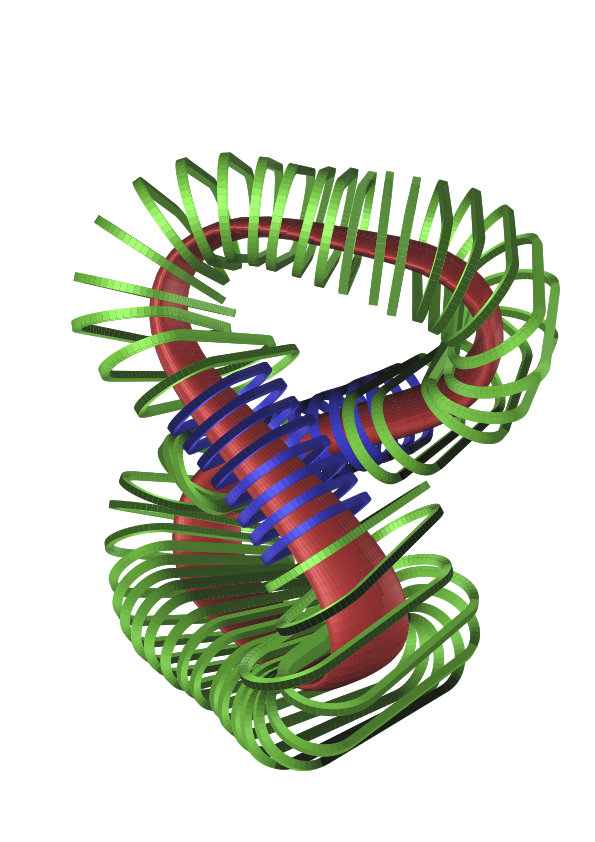
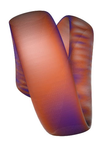
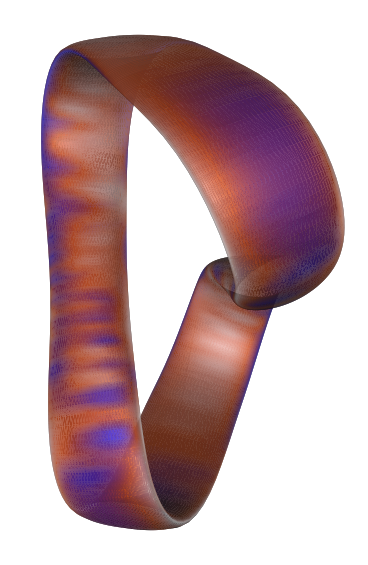
A view of the full configuration is shown in Fig. 7; the configuration bears a striking resemblance to the early conceptual “Model C” design, which was never built [2]. Note that the optimization was performed at aspect ratio but it was decided afterward to increase the aspect ratio of the resulting configuration to in order to allow more space to fit the coils.

5.1 Coil optimization
Coil designs were carried out using the ONSET [45] suite of codes. Because a first analysis using NESCOIL [46, 47] had indicated that the coils would deviate only slightly from a planar shape, the optimisation was carried out using planar coils only. Two types of coils were used: smaller coils with reduced current close to the node of the “8”, designed in size so as to avoid intersection of opposing coils, and larger coils for the remainder of the configuration so as to minimise the modular ripple. The small coils are somewhat closer to the plasma boundary and set the minimum coil-to-boundary distance, which is about half the average minor radius of the configuration.
An analysis of the field error (Fig. 9) shows that the modular field error gradually stops being the dominant cause of field error, starting at a design point with 16 independent coils. On the right hand side of Fig. 9 poloidally elongated structures are identified on the long straight sections that clearly are the effect of the modular ripple. On the left hand side, however, wide areas of normal magnetic field error are seen on the outboard side of the short straight sections, similar in magnitude to the ripple seen in the long sections.
The coil set presented here achieves a maximum field error of 4.2% and a mean error if 1.3%. These values tend to result in a good alignment of the coil-generated flux surfaces with those of the design configuration.
6 Conclusion
In this paper, we have revisited the idea of Spitzer’s figure-8 stellarator, re-imagning it as a modern quasi-isodynamic design. Historically, the brief investigation of the figure-8 concept brought forth concerns about plasma stability, and the alternative that emerged, the classical stellarator, was also regarded as simpler to build. The initial results found here, including high susceptibility to a stabilizing vacuum magnetic well, and a planar set of coils (the first QI design achieving this), hint that a QI figure-8 stellarator might actually have strengths with respect to both stability and ease of construction.
A key feature linking both properties is the weak shaping of the plasma boundary, which we have traced to a fundamental geometric property at the heart of figure-8 geometry: the magnetic axis curve at the core of the device manages to rotate without twisting. This means that its mostly elliptical shape stays closely aligned with the smoothly moving frame of the axis, and the lack of twist means that very little high-order shaping (e.g. triangularity or ‘bean’ shaping) is needed to produce a stabilizing magnetic well.
Intuitively, weak shaping appears to have dramatic consequences on the coil design, with the case investigated here requiring only planar ‘racetrack’ shapes. Future work could build on this example, or lead to general strategies to reduce coil complexity, with this being one of the most frequently cited criticism of optimized stellarators.
The recent extension of theoretical methods, chiefly near-axis theory, has lead researchers toward unusual shapes like the figure-8 that might otherwise have been neglected. Until now, numerical tools such as equilibrium codes like VMEC [48], which have formed the backbone of numerical stellarator optimization, were not well-suited for many such shapes. It is ironic that these tools now require updating to investigate the very first, and in some sense simplest stellarator concept. The extension of the GVEC code [15] is a first step in this direction. The ‘re-optimization’ near-axis configurations for a magnetic well is only a first demonstration of this kind of application. The figure-8 is a particularly pathological case for using cylindrical coordinates, and the benefits of doing optimization may extend to more conventional cases, providing a condensed (lower-dimensional) representation for shapes that have posed a challenge for optimization.
The final design presented here was chosen to have an aspect ratio of , for direct comparison with typical for QI stellarators, i.e. to show the differences that arise at a similar design point. The inclination of the axis (“figure-8-ness”) was only limited to allow space for the planar coils at the location of minimum field strength. Practically speaking, a future figure-8 device could be explored for which such parameter choices are adjusted, for instance if more space for the coils is desired, or compactness (smaller aspect ratio) is desired for improved confinement, with some trade-offs in terms of coil distance and/or complexity.
Moving forward there are many practical questions to tackle in all the usual areas, like (global MHD) stability, turbulence properties, confinement, plasma currents, and resilience of the equilibrium to finite plasma pressure. There are also some fundamental theoretical avenues to investigate, such as a broader search for configurations with low integrated torsion or points of zero torsion that may show some of the benefits observed here.
Overall, the results of this paper seem to cast the figure-8 in a new light. With more work a fusion-relevant design might be found, or the lessons learned might inspire a related design that borrows some of the strengths of the figure-8.
Acknowledgments
We thank Per Helander and Carolin Nührenberg for helpful discussions. E. R. was supported by a grant of the Alexander-von-Humboldt-Stiftung, Bonn, Germany, through a postdoctoral research fellowship.
References
References
- [1] Goldman L, Spitzer Jr L. Preliminary Experimental Results with the Model A Stellarator. Princeton Univ., NJ Project Matterhorn; 1953.
- [2] Farber WR, Fraser JC, Grove DJ, Mills RG, Rashevsky M, Schultz MA, et al.. A Conceptual Design of the Model C Stellarator; 1956. U.S. Atomic Energy Commision Report No. NYO-7309 (PMS-19). Available from: https://www.osti.gov/biblio/4299735.
- [3] Spitzer Jr L, Grove D, Johnson W, Tonks L, Westendorp W. Problems of the stellarator as a useful power source. Princeton Univ., NJ Project Matterhorn; 1954.
- [4] Spitzer J Lyman. The Stellarator Concept. The Physics of Fluids. 1958 07;1(4):253-64. Available from: https://doi.org/10.1063/1.1705883.
- [5] Bishop AS. Project Sherwood; the U.S. program in controlled fusion. United States of America: Addison-Wesley Pub. Co.; 1958.
- [6] Hindenlang F, Maj O, Strumberger E, Rampp M, Sonnendrücker E. GVEC: a newly developed 3D ideal MHD Galerkin variational equilibrium code; 2019. Annual Meeting of the Simons Collaboration on Hidden Symmetries and Fusion Energy.
- [7] Dudt DW, Kolemen E. DESC: A stellarator equilibrium solver. Physics of Plasmas. 2020 Oct;27(10):102513. Available from: https://doi.org/10.1063/5.0020743.
- [8] Gori S, Lotz W, Nührenberg J. Quasi-isodynamic Stellarators. Theory of Fusion Plasmas (Proc Joint Varenna-Lausanne Int Workshop). 1996:335-42.
- [9] Helander P, Nührenberg J. Bootstrap current and neoclassical transport in quasi-isodynamic stellarators. Plasma Physics and Controlled Fusion. 2009 feb;51(5):055004. Available from: https://doi.org/10.1088/0741-3335/51/5/055004.
- [10] Nührenberg J. Development of quasi-isodynamic stellarators. Plasma Physics and Controlled Fusion. 2010;52(12):124003. Available from: http://stacks.iop.org/0741-3335/52/i=12/a=124003.
- [11] Plunk GG, Landreman M, Helander P. Direct construction of optimized stellarator shapes. Part 3. Omnigenity near the magnetic axis. Journal of Plasma Physics. 2019;85(6):905850602.
- [12] Camacho Mata K, Plunk GG, Jorge R. Direct construction of stellarator symmetric -field period magnetic configurations. Journal of Plasma Physics (to be submitted). 2022.
- [13] Plunk GG, et al. A geometric approach to constructing quasi-isodynamic fields; 2024. In preparation.
- [14] Rodríguez E, Plunk GG, Jorge R. Near-axis description of stellarator-symmetric quasi-isodynamic stellarators to second order; 2024. Available from: https://arxiv.org/abs/2409.20328.
- [15] Hindenlang F, Plunk GG, Maj O. A generalized Frenet frame for computing MHD equilibria in stellarators. Plasma Physics and Controlled Fusion submitted. 2024. Available from: https://arxiv.org/abs/2410.17595.
- [16] Babin R, et al. pyGVEC: python interface to the equilibrium solver GVEC for integration into stellarator optimization. in preparation. 2024.
- [17] Jorge R, Plunk GG, Drevlak M, Landreman M, Lobsien JF, Camacho Mata K, et al. A single-field-period quasi-isodynamic stellarator. Journal of Plasma Physics. 2022;88(5):175880504.
- [18] Landreman M, Sengupta W. Direct construction of optimized stellarator shapes. Part 1. Theory in cylindrical coordinates. Journal of Plasma Physics. 2018;84(6):905840616.
- [19] Boozer AH. Transport and isomorphic equilibria. The Physics of Fluids. 1983 02;26(2):496-9. Available from: https://doi.org/10.1063/1.864166.
- [20] Nührenberg J, Zille R. Quasi-helically symmetric toroidal stellarators. Physics Letters A. 1988;129(2):113 117. Available from: http://www.sciencedirect.com/science/article/pii/0375960188900801.
- [21] Rodriguez E, Helander P, Bhattacharjee A. Necessary and sufficient conditions for quasisymmetry. Physics of Plasmas. 2020;27(6).
- [22] Frenet F. Sur les courbes à double courbure. Journal de mathématiques pures et appliquées. 1852;17:437-47.
- [23] Animov Y. Differential geometry and topology of curves. CRC press; 2001.
- [24] Garren DA, Boozer AH. Magnetic field strength of toroidal plasma equilibria. Physics of Fluids B. 1991;3(10):2805-21. Available from: http://scitation.aip.org/content/aip/journal/pofb/3/10/10.1063/1.859915.
- [25] Plunk GG. The Quasi-isodynamic Stellarator; 2023. Simons Collaboration on Hidden Symmetries and Fusion Energy Annual Meeting. Available from: https://www.simonsfoundation.org/event/simons-collaboration-on-hidden-symmetries-and-fusion-energy-annual-meeting-2023/.
- [26] Carroll D, Köse E, Sterling I. Improving Frenet’s frame using Bishop’s frame. Journal of Mathematics Research. 2013;5(4):97-106.
- [27] Dewar R, Hudson S. Stellarator symmetry. Physica D: Nonlinear Phenomena. 1998;112(1-2):275-80.
- [28] Rodríguez E, Sengupta W, Bhattacharjee A. Phases and phase-transitions in quasisymmetric configuration space. Plasma Physics and Controlled Fusion. 2022;64(10):105006.
- [29] Mata KC, Plunk GG. Helicity of the magnetic axes of quasi-isodynamic stellarators. Journal of Plasma Physics. 2023;89(6):905890609.
- [30] Moffatt HK, Ricca RL. Helicity and the Călugăreanu invariant. Proceedings of the Royal Society of London Series A: Mathematical and Physical Sciences. 1992;439(1906):411-29.
- [31] Fuller Jr EJ. The geometric and topological structure of holonomic knots. University of Georgia; 1999.
- [32] Fuller F. The writhing number of a space curve. Proc Natl Acad Sci. 1971;68(4):815-9.
- [33] Lawrence JD. A catalog of special plane curves. Courier Corporation; 2013.
- [34] Landreman M, Sengupta W, Plunk GG. Direct construction of optimized stellarator shapes. Part 2. Numerical quasisymmetric solutions. Journal of Plasma Physics. 2019;85(1):905850103.
- [35] Rodríguez E. Magnetohydrodynamic stability and the effects of shaping: a near-axis view for tokamaks and quasisymmetric stellarators. Journal of Plasma Physics. 2023;89(2):905890211.
- [36] Pfefferlé D, Gunderson L, Hudson SR, Noakes L. Non-planar elasticae as optimal curves for the magnetic axis of stellarators. Physics of Plasmas. 2018;25(9).
- [37] Mercier C. Equilibrium and stability of a toroidal magnetohydrodynamic system in the neighbourhood of a magnetic axis. Nuclear Fusion. 1964;4(3):213. Available from: http://stacks.iop.org/0029-5515/4/i=3/a=008.
- [38] Cary JR, Shasharina SG. Omnigenity and quasihelicity in helical plasma confinement systems. Physics of Plasmas. 1997;4(9):3323-33. Available from: http://dx.doi.org/10.1063/1.872473.
- [39] Drevlak M, Beidler CD, Geiger J, Helander P, Turkin Y. Optimisation of stellarator equilibria with ROSE. Nuclear Fusion. 2018 nov;59(1):016010. Available from: https://dx.doi.org/10.1088/1741-4326/aaed50.
- [40] Greene JM. A brief review of magnetic wells. Comments on Plasma Physics and Controlled Fusion. 1997;17:389-402.
- [41] Freidberg JP. ideal MHD. Cambridge University Press; 2014.
- [42] Mercier C. Equilibrium and stability of a toroidal magnetohydrodynamic system in the neighbourhood of a magnetic axis. Nuclear Fusion. 1964 sep;4(3):213. Available from: https://dx.doi.org/10.1088/0029-5515/4/3/008.
- [43] Landreman M, Jorge R. Magnetic well and Mercier stability of stellarators near the magnetic axis. Journal of Plasma Physics. 2020;86(5):905860510.
- [44] Rodriguez E, Helander P, Goodman A. The maximum-J property in quasi-isodynamic stellarators. Journal of Plasma Physics. 2024;90(2):905900212.
- [45] Drevlak M. Coil Designs for a Quasi-Axially Symmetric Stellarator. 20th Symposium on Fusion Technology. Association Euratom-CEA Cadarache;. p. 883.
- [46] Merkel P. Solution of stellarator boundary value problems with external currents. Nuclear Fusion. 1987;27(5):253-64.
- [47] Merkel P, Drevlak M. Coils for 3d MHD equilibria. 25th EPS Conference on Controlled Fusion and Plasma Physics; 1998. p. 1745.
- [48] Hirshman SP, Whitson JC. Steepest-descent moment method for three-dimensional magnetohydrodynamic equilibria. The Physics of Fluids. 1983;26(12):3553-68. Available from: http://aip.scitation.org/doi/abs/10.1063/1.864116.