A universal neutral-atom quantum computer with individual
optical addressing and non-destructive readout
Abstract
Quantum computers must achieve large-scale, fault-tolerant operation to deliver on their promise of transformational processing power [1, 2, 3, 4]. This will require thousands or millions of high-fidelity quantum gates and similar numbers of qubits [5]. Demonstrations using neutral-atom qubits trapped and manipulated by lasers have shown that this modality can provide high two-qubit gate (CZ) fidelities and scalable operation [6, 7, 8, 9, 10]. However, the gates in these demonstrations are driven by lasers that do not resolve individual qubits, with universal computation enabled by physical mid-circuit shuttling of the qubits. This relatively slow operation will greatly extend runtimes for useful, large-scale computation. Here we demonstrate a universal neutral-atom quantum computer with gate rates limited by optical switching times, rather than shuttling, by individually addressing tightly focused laser beams at an array of single atoms. We achieve CZ fidelity of 99.35(4)% and local single-qubit gate fidelity of 99.902(8)%. Moreover, we demonstrate non-destructive readout of alkali-atom qubits with sub-percent loss, which boosts operational speed. This technique also enables us to measure 99.73(3)% CZ fidelity with atom-loss events excluded, which is a record among long-lived neutral-atom qubits and highlights the path to higher fidelity and error correction. Our results represent a critical step towards large-scale, fault-tolerant neutral-atom quantum computers that can execute computations on practical timescales.
1 Introduction
Quantum computers promise to reduce computational energy consumption and solve classically expensive or intractable problems in a range of fields including material science, machine learning, security, chemistry, energy, finance, medicine, and pharmaceutical development [1, 2, 3, 4, 11, 12, 13, 14, 15]. Recent analyses suggest that realization of practical utility will require fault-tolerant operation [5]. This in turn requires quantum error correction (QEC), which comes with large overhead in the number of qubits and requires high one- and two-qubit quantum gate fidelities. The field’s progress along this path has entered a phase of experimental demonstrations [16, 17, 7]. Among the diverse modalities proposed for large-scale fault-tolerant quantum computation [18], the neutral-atom approach is one of the most promising candidates and has become a leader in the combination of qubit count, universal gate-based circuit operation, connectivity, and quantum error correction [7, 19, 20]. The rapid progress of neutral atoms for quantum computing can be attributed to the combination of naturally identical qubits; long coherence times due to decoupling from the environment [21]; switchable qubit interaction strengths across 12 orders of magnitude [22]; sub-microsecond, high-fidelity, scalable gates [6, 23]; and the ability to trap and manipulate large, dense, multi-dimensional qubit arrays [24, 19, 25], as was recently highlighted with a demonstration of error-corrected logical qubits [7].
Two architectural approaches have emerged for neutral-atom quantum processors. One [7] relies on simultaneously shuttling multiple qubits to and from a single, dedicated zone for implementing gates. This allows flexible qubit connectivity and avoids the need for near-diffraction-limited addressing beams but increases compilation complexity [26] and limits gate rates due to constraints on the speed of atom movement[27]. High gate rates are important for maintaining practical computation times, particularly in light of the physical qubit count and gate depth overheads required for fault-tolerant operation. An alternative approach [20] keeps the qubits stationary and addresses them individually with steerable laser beams, enabling gate rates limited only by optical switching, which is inherently faster than atom movement. This stationary qubit approach poses challenges for achieving high gate fidelities and does not natively support all-to-all connectivity, but it offers the promise of faster circuits, in direct support of long-term fault-tolerant operations [28]. Here, we present a full-stack neutral-atom quantum computer using gates based on individual optical addressing instead of atom motion. Overcoming the challenges specific to this architecture, we achieve entangling gate fidelity of 99.35(4)%, already exceeding QEC thresholds for certain codes [29, 30, 31, 32]. Our results open the door to faster approaches for fault-tolerant operation that exclusively use individual optical addressing of stationary qubits, or that combine this with some atom shuttling to optimize execution of error-corrected circuits. We further advance the state-of-the-art by incorporating non-destructive qubit readout, immediately enabling faster computations and establishing a key ingredient for future mid-circuit measurements and error correction.
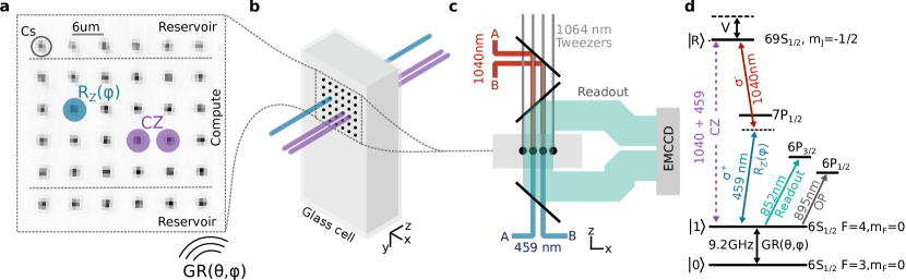
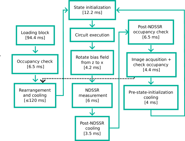
2 A neutral-atom architecture with individual optical addressing
Building on prior work [20], we present a full-stack neutral-atom quantum computer using an individual optical addressing architecture. Arbitrary quantum circuits can be submitted via the cloud, where they are compiled333via Infleqtion Superstaq [33] into a universal native gate set consisting of global microwave rotations, arbitrary local rotations, and nearest-neighbor controlled-Z (CZ) gates. The qubits are optically trapped Cs atoms, with and encoded in the and clock states of the ground state hyperfine manifold, respectively. The atoms are trapped out of a cold atomic beam444Infleqtion PICAS, cooled, and rearranged by an optical tweezer to form a defect-free array. Fig. 1 illustrates a 24-qubit computational array alongside 12 reservoir atoms, formed in a 1064 nm tweezer array (see Methods Sec. 6.1). After state preparation via optical pumping, arbitrary circuits are implemented with microwave and laser pulses, followed by non-destructive state-selective readout (NDSSR) of the qubit state. During this readout the qubits remain trapped in the optical tweezers with high probability, allowing re-initialization and re-use of the same atomic array for the next shot (see Sec. 4). After the requested number of measurements is collected, circuit results are returned to the user. Throughout this process feed-forward stabilization is applied to background electric and magnetic fields, and lasers are stabilized on various timescales using both optical power measurements and atom-based signals.
Unique to this system is the optical design supporting laser-based local rotations and CZ gates. The former requires application of 459 nm light to a single atom, and the latter requires simultaneous application of 459 nm and 1040 nm light to a pair of atoms to drive two-photon Rydberg excitation. To implement these gates, we send each laser through a sequence of three acousto-optic devices: one for pulse shaping and two for beam steering. The pulsed and steered beams are then focused to nearly diffraction-limited spots on the atom array (see Fig. 1). Using both direct optical measurements and atom-based beam profiling, we confirm that our 459 and 1040 beams are focused to spot sizes of 2.8 and 3.0 ( intensity radii) in the atom plane. Critically, these spots are smaller than the atom spacing of 6 , allowing us to address all qubits individually. With this approach, we can alternate between CZ and local gates (on select target qubits) with a timescale limited only by the beam-steering devices. Our current acousto-optic deflectors (AODs) used as beam-steering devices can be re-aimed with a timescale of 2 . In future devices, combining AODs with spatial light modulators (SLMs) can enable fast, individually addressed gates on multiple qubits simultaneously [34]. With this approach our individual-addressing architecture supports parallel gate operations while maintaining high gate rates.
A practical consideration for this individual addressing design is the crosstalk that can occur from residual beam intensity reaching a neighboring atom. For instance, given our beam waists, one predicts 0.03% intensity reaching neighboring qubits. In practice, we find crosstalk intensities up to x higher, likely due to optical aberrations. We provide a thorough discussion of the implications of this crosstalk in Methods Sec. 6.7, and summarize the results here. One effect of this crosstalk is residual light reaching spectator atoms not participating in the gate. For our current parameters, we estimate that this produces an error contribution smaller than per gate. Moreover, it is a predictable unitary error that can be compiled away [33]. The other important impact of crosstalk is on the entangling gate itself, where interference between the control and target illumination can significantly perturb the gate dynamics. However, we find that this error contribution can be made negligible by ensuring that the fields interfere at a frequency much higher than the Rabi frequency of the Rydberg excitation. We design our addressing system to satisfy this requirement. For each wavelength, we branch the single source laser into two fully independent beam-shaping and beam-steering paths (labeled A and B in Fig. 1). Thus, in a CZ gate, the Rydberg laser light reaching the control and target qubits have disparate acousto-optic frequency shifts, resulting in controllable crosstalk beatnote frequencies in the range MHz (see Methods Sec. 6.7). This dual beamline system enables our processor to tolerate greater crosstalk intensity at higher array density, achieving higher blockade strength, while still addressing qubits individually and minimizing the impact of crosstalk on neighboring atoms.
3 Quantum processor implementation and characterization
Optically trapped Cesium atoms offer a hyperfine qubit with excellent coherence properties. We find a trap vacuum lifetime of 26(2) s, limited by background gas collisions, and measure an atom temperature of 2.6(3) K through a combination of release-recapture[35] and ground-Rydberg coherence measurements. This temperature alone would permit a qubit coherence time of about 42 ms. In practice we measure ms, and we attribute this additional decoherence to magnetic field shot-to-shot fluctuation of mG at our bias of 11.15 G, as supported by measurements of on magnetically sensitive hyperfine transitions. By concatenating repeated XY8 dynamical decoupling sequences, we can extend beyond the capability of our hardware to accurately measure it—our best estimate is 2.8 s, with a 97% confidence interval lower bound of 128 ms.
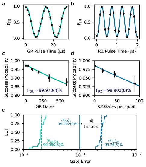
Our single-qubit gate set consists of global (GR) and local rotations. The former are implemented via a uniform pulsed microwave field resonant with the magnetically insensitive qubit transition. The duration and phase of the pulse determines and , respectively. Fig. 2a illustrates Rabi oscillations driven by this microwave field. With this system, we have reached Rabi rates as high as kHz, enabling an gate time of 4.1 s. We characterize the full set of GR Cliffords across a 24-qubit system using randomized benchmarking (Fig. 2b, d), and find an average fidelity of 99.980%, with an ensemble standard deviation of 0.003% (Fig. 2) and a typical fit uncertainty of 0.004%.
Local rotations are implemented via the differential light shift arising from a locally addressed, 459 nm laser beam that off-resonantly addresses the transition from to the excited state with a detuning from the center of mass. Fig. 2b presents Ramsey measurements of a differential light shift of MHz, enabling an gate time of 250 ns. We characterize fidelity for two values of using a novel form of interleaved randomized benchmarking (IRB), which samples rotation angles uniformly distributed over (see Methods Sec. 6.3). We first characterize the full 24-qubit array with MHz. This characterization uses a maximum IRB depth of gates per qubit, which entails redirecting the beam-steering AODs times in a 15 ms circuit. We find an average fidelity of 99.76%, with an ensemble standard deviation of 0.03% (Fig. 2e). To properly account for the difference between leakage and true depolarization, the fidelity calculation includes an estimate of the scattering error due to non-zero population of the intermediate state (Methods Sec. 6.3). Our observed error is dominated by this scattering, which can be suppressed by using larger detuning. Indeed, changing to GHz, we measure, for a single qubit, a higher fidelity of 99.902(8)% (see Fig. 2d). The residual error of 0.098(1)% is largely explained by the remaining leakage probability of 0.066% and laser pulse energy fluctuation.
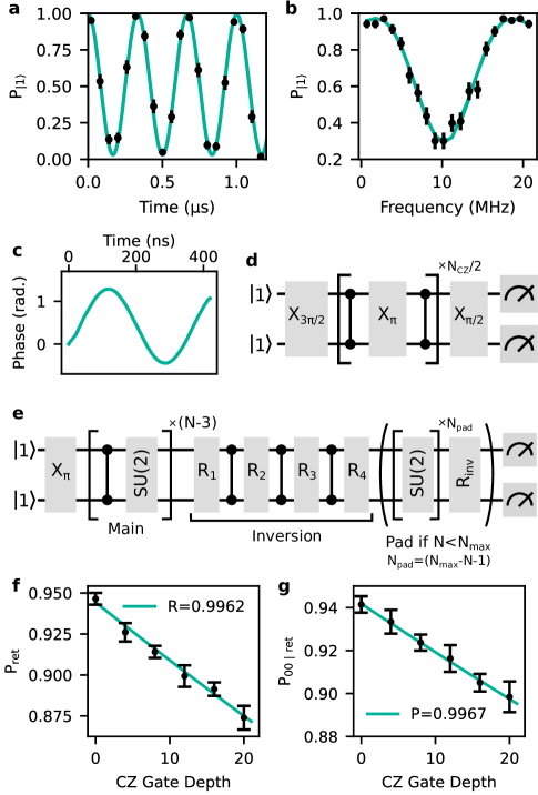
Our quantum processor implements the two-qubit controlled-Z (CZ) gate, which, combined with arbitrary single-qubit rotations, is sufficient for universal quantum computation. The gate is based on simultaneous excitation of the control and target qubits to a Rydberg state, where blockade interactions provide inter-qubit coupling. In particular, we use two-photon excitation (459 nm + 1040 nm) to couple the state to the Rydberg level. The single-photon intensities are defined by the GHz detuning from the intermediate state, the MHz light shift applied to the qubit by the 459 nm laser and the MHz Rabi frequency of Rydberg excitation (Fig. 3a). We measure a blockade interaction energy of MHz (Fig. 3b). We implement an approximation of the time-optimal Rydberg CZ gate [23] using a pulse of duration 7.85/ = 416 ns with a sinusoidal phase profile (implemented via electro-optic modulation of the 1040 nm beam; see Fig. 3c). The full CZ gate consists of this phase-modulated Rydberg pulse followed by single-qubit phase corrections to produce the canonical gate. We first calibrate the uncorrected gate, using a cost function that is insensitive to the single-qubit phases [6] (Fig. 3d), then calibrate the phase corrections (see Methods Sec. 6.4).
We characterize our CZ gates using randomized benchmarking circuits in which CZ gates alternate with global single-qubit gates (see Fig. 3e). Symmetric benchmarking is discussed in detail in Ref. [36], and approaches similar to ours were used in Refs. [6, 37, 8]. This approach has limitations; for example, swap errors go completely undetected, and it strictly only characterizes the performance of the gate on a subset of two-qubit input states. Nevertheless, it is known to perform well given the error profile of neutral-atom platforms. To validate application of the approach to our gate, we perform density matrix simulations of our benchmarking procedure using a realistic microscopic error model for the gate (see Methods Sec. 6.6) and find agreement between the fidelity extracted from benchmarking and the true gate fidelity averaged over Haar-random input states, reproducing findings from prior applications of the technique [6, 37].
Figure 3 presents CZ benchmarking results for a single pair of atoms. In these circuits single-qubit phase corrections are implemented via a combination of local and virtual phase shifts to the local oscillator, as in Ref. [38]. Because we characterize a single qubit pair, the beam-steering AODs are statically driven throughout the control sequence. By following each NDSSR measurement immediately with an occupancy measurement, we are able to separately characterize the two-atom survival probability (% per gate) and cycle polarization (%). Combining these with a model-based estimate of the leakage probability (see Methods Sec. 6.5), we extract a CZ fidelity of %. The leading physical mechanisms contributing to the observed % CZ gate error are leakage due to the finite lifetime of the intermediate state, leakage and loss due to the finite lifetime of the Rydberg level, and shot-to-shot intensity fluctuations of the Rydberg laser beams. We estimate the contribution from optical crosstalk to CZ error to be % in our current configuration, with a straightforward path to further reduction (see Methods Sec. 6.7).
NDSSR allows us to filter the data based on atom retention and calculate a post-selected CZ fidelity of 99.73(3)% (see Methods Sec. 6.5). This % atom loss error may be converted to erasure through a leakage-detection measurement in which an ancilla becomes entangled with the presence/absence of an atom in a qubit state (rather than its logical state) [39], enabling the use of erasure-specific techniques to achieve improved correction performance [40].
4 Non-destructive State Selective Readout
While neutral-atom platforms have demonstrated significant improvements in gate fidelity and qubit count scaling that make neutral atoms a leading modality for quantum computing, there has been relatively less emphasis on their shot rate. Non-circuit operations such as atom loading and arrangement are expected to be a non-negligible part of the total operation time for measurement schemes based on destructive readout; a non-destructive readout scheme with repetitive measurements can significantly increase shot rate by amortizing the cost of these non-circuit operations and can enable mid-circuit measurements for fault-tolerant operation.
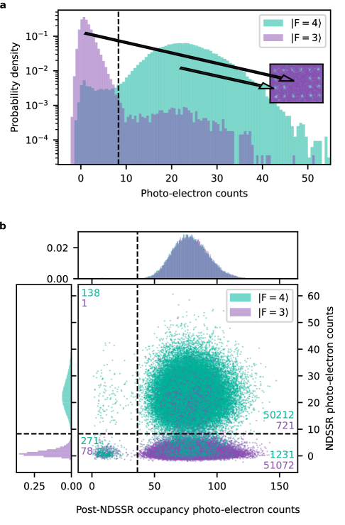
We implement the non-destructive state detection method demonstrated in Ref. [41] with a few critical improvements (see Methods 6.8). During the state detection sequence, qubit state is optically pumped to the stretched state , where we can detect fluorescence from the closed transition, while remains dark. By strategically alternating between illumination with trap light and readout light, we mitigate the deleterious effects of excited state light shift and dipole force fluctuations, and we reach a state-averaged loss rate of while achieving bright-dark discrimination fidelity of 99.6(2)%with 6 ms of camera exposure time. The imaging performance and the state-discrimination fidelity of the readout scheme is analyzed from a large dataset of images collected during state preparation and measurement (SPAM) characterization experiments, each of which prepares all qubits to be in (bright) or (dark) (Fig. 4). The raw state-discrimination fidelity without state preparation or atom loss correction is 97.7(5)%, limited by bright state detection error of 3.1(7)% and dark state detection error of 1.6(5)%. Note that state preparation error, which includes failure to optically pump into during Raman sideband cooling and failure to coherently transfer to using microwave pulses (see Sec. 6.2), is distributed across both types of state detection errors.
The shot rate enhancement from repetitive non-destructive measurements is demonstrated by recording 8.2(2) Hz shot rate for a 15-qubit Greenberger–Horne–Zeilinger (GHZ) state preparation circuit executed within a 24-qubit array (see Sec. 6.8.3), compared to an estimated single-measurement shot rate of Hz. These experiments were performed without Raman sideband cooling, the inclusion of which adds additional time to each measurement that cannot be amortized (see Methods Fig. 10). To the best of our knowledge, the only other demonstration of repeated non-destructive measurements of neutral-atom-based quantum circuits utilizing a universal gate set is found in Ref. [9]. This demonstration used an alkaline-earth species (strontium-88) with 10 ms of exposure time for non-destructive measurement of ancilla atoms with 3.5% atom loss rate.
The non-destructive readout method for alkali atomic species demonstrated in this work provides the starting point for repetitive mid-circuit readout of ancilla qubits in dual-alkali-species-based logical qubit architectures. The atom loss rate can be further reduced by using shorter exposure times and advanced camera image binarization algorithms that work at low photon counts [42]. The depumping error during imaging can be improved with technical improvements in polarization purity and with microwave-assisted state-selective repumping during imaging [43].
5 Outlook
This work advances the state-of-the-art for individually addressed entangling gates in a neutral-atom platform, and we foresee a clear path towards the error levels required for fault tolerance. Control errors may be reduced by reaching lower atom temperatures, better stabilizing laser power and frequency, and using robust gate protocols[44, 45]. Straightforward changes such as increasing the intermediate-state detuning will immediately reduce scattering error. Moving forward, scattering error can be eliminated by transitioning to single-photon Rydberg excitation [38, 37], which also reduces the complexity of light shifts on atomic resonances. The path for scaling our qubit array is also well-established, with demonstrations[46] suggesting the feasibility of trapping qubits in a single array, with the option to improve trapping lifetimes by operating at cryogenic temperatures[47]. The non-destructive readout we present here already enables state-of-the-art shot rate, and paths towards even faster readout are being developed[48, 49]. Finally, we note that our ability to achieve high ground-Rydberg coherence () at is a unique advantage in the field, enabled by our electric field control. Since the Rydberg interaction scales with , operating at higher unlocks greater connectivity, which is valuable for QEC protocols and applications[28].
For quantum computers to provide meaningful scientific and commercial value, they will likely need to support fault-tolerant operation on at least 100 logical qubits[50, 51, 5], and neutral-atom architectures are evolving rapidly towards that goal. This work demonstrates important new capabilities on that path, namely the ability to implement individually addressed high fidelity entangling gates and non-destructive state-selective readout, which collectively enable faster qubit operations and a broader set of QEC protocols. Ultimately, a compelling architecture for fast, fault-tolerant quantum computing is likely to integrate these techniques alongside other demonstrated neutral-atom capabilities, including dual-species platforms[52, 53], mid-circuit measurement[54, 55, 52, 53, 43, 7], and alternate addressing architectures[20, 56, 57, 7]. The advanced optical control techniques we demonstrate here also extend directly to alternative atomic species[20, 37, 58, 7], as well as multi-qubit () gates[59], which can further optimize logical operations[60].
References
- [1] Shor, P. W. Algorithms for quantum computation: Discrete logarithms and factoring. Proceedings - Annual IEEE Symposium on Foundations of Computer Science, FOCS 124–134 (1994).
- [2] McArdle, S., Endo, S., Aspuru-Guzik, A., Benjamin, S. C. & Yuan, X. Quantum computational chemistry. Rev. Mod. Phys. 92, 015003 (2020).
- [3] Gao, X., Anschuetz, E. R., Wang, S. T., Cirac, J. I. & Lukin, M. D. Enhancing generative models via quantum correlations. Physical Review X 12, 021037 (2022).
- [4] Santagati, R. et al. Drug design on quantum computers. Nature Physics 20, 549–557 (2024).
- [5] Hoefler, T., Häner, T. & Troyer, M. Disentangling hype from practicality: On realistically achieving quantum advantage. Communications of the ACM 66, 82–87 (2023).
- [6] Evered, S. J. et al. High-fidelity parallel entangling gates on a neutral-atom quantum computer. Nature 622, 268–272 (2023).
- [7] Bluvstein, D. et al. Logical quantum processor based on reconfigurable atom arrays. Nature 626, 58–65 (2024).
- [8] Peper, M. et al. Spectroscopy and modeling of rydberg states for high-fidelity two-qubit gates (2024). URL https://arxiv.org/abs/2406.01482v1.
- [9] Finkelstein, R. et al. Universal quantum operations and ancilla-based readout for tweezer clocks (2024). URL https://arxiv.org/abs/2402.16220v2.
- [10] Wu, T. Y. Neutral-atom quantum computer with 87Sr nuclear-spin qubits (2024). URL https://meetings.aps.org/Meeting/DAMOP24/Session/J06.3.
- [11] Date, P., Arthur, D. & Pusey-Nazzaro, L. Qubo formulations for training machine learning models. Scientific Reports 11, 1–10 (2021).
- [12] Ma, H., Govoni, M. & Galli, G. Quantum simulations of materials on near-term quantum computers. npj Computational Materials 6, 1–8 (2020).
- [13] Koretsky, S. et al. Adapting quantum approximation optimization algorithm (qaoa) for unit commitment. Proceedings - 2021 IEEE International Conference on Quantum Computing and Engineering, QCE 2021 181–187 (2021).
- [14] Perlin, M. A. et al. Q-chop: Quantum constrained hamiltonian optimization (2024). URL https://arxiv.org/abs/2403.05653v1.
- [15] Ramesh, S., Tomesh, T., Riesenfeld, S. J., Chong, F. T. & Pearson, A. T. Quantum computing for oncology. Nature Cancer 5, 811–816 (2024).
- [16] Google Quantum AI. Suppressing quantum errors by scaling a surface code logical qubit. Nature 614, 676–681 (2023).
- [17] da Silva, M. P. et al. Demonstration of logical qubits and repeated error correction with better-than-physical error rates (2024). URL https://arxiv.org/abs/2404.02280v2.
- [18] Bergou, J., Hillery, M. & Saffman, M. Quantum Information Processing: Theory and Implementation, 2nd edition (Springer, 2021).
- [19] Manetsch, H. J. et al. A tweezer array with 6100 highly coherent atomic qubits (2024). URL https://arxiv.org/abs/2403.12021v2.
- [20] Graham, T. M. et al. Multi-qubit entanglement and algorithms on a neutral-atom quantum computer. Nature 604, 457–462 (2022).
- [21] Barnes, K. et al. Assembly and coherent control of a register of nuclear spin qubits. Nature Communications 13, 1–10 (2022).
- [22] Saffman, M., Walker, T. G. & Mølmer, K. Quantum information with Rydberg atoms. Reviews of Modern Physics 82, 2313–2363 (2010).
- [23] Jandura, S. & Pupillo, G. Time-optimal two- and three-qubit gates for Rydberg atoms. Quantum 6, 712 (2022).
- [24] Norcia, M. A. et al. Iterative assembly of 171-Yb atom arrays with cavity-enhanced optical lattices. PRX Quantum 5, 030316 (2024).
- [25] Huft, P. et al. Simple, passive design for large optical trap arrays for single atoms. Physical Review A 105, 063111 (2022).
- [26] Tan, D. B., Bluvstein, D., Lukin, M. D. & Cong, J. Compiling quantum circuits for dynamically field-programmable neutral atoms array processors. Quantum 8, 1281 (2024).
- [27] Lam, M. R. et al. Demonstration of quantum brachistochrones between distant states of an atom. Physical Review X 11, 011035 (2021).
- [28] Poole, C., Graham, T. M., Perlin, M. A., Otten, M. & Saffman, M. Architecture for fast implementation of qLDPC codes with optimized Rydberg gates (2024). URL https://arxiv.org/abs/2404.18809v1.
- [29] Knill, E. Quantum computing with realistically noisy devices. Nature 434, 39–44 (2005).
- [30] Sahay, K., Jin, J., Claes, J., Thompson, J. D. & Puri, S. High-threshold codes for neutral-atom qubits with biased erasure errors. Physical Review X 13, 041013 (2023).
- [31] Bravyi, S. et al. High-threshold and low-overhead fault-tolerant quantum memory. Nature 627, 778–782 (2024).
- [32] Hong, Y., Marinelli, M., Kaufman, A. M. & Lucas, A. Long-range-enhanced surface codes. Physical Review A 110, 022607 (2024).
- [33] Campbell, C. et al. Superstaq: Deep optimization of quantum programs. In 2023 IEEE International Conference on Quantum Computing and Engineering (QCE), 1020–1032 (IEEE, 2023).
- [34] Graham, T. M., Oh, E. & Saffman, M. Multiscale architecture for fast optical addressing and control of large-scale qubit arrays. Applied Optics 62, 3242–3251 (2023).
- [35] Tuchendler, C., Lance, A. M., Browaeys, A., Sortais, Y. R. P. & Grangier, P. Energy distribution and cooling of a single atom in an optical tweezer. Phys. Rev. A 78, 033425 (2008).
- [36] Baldwin, C. H., Bjork, B. J., Gaebler, J. P., Hayes, D. & Stack, D. Subspace benchmarking high-fidelity entangling operations with trapped ions. Physical Review Research 2, 013317 (2020).
- [37] Ma, S. et al. High-fidelity gates and mid-circuit erasure conversion in an atomic qubit. Nature 622, 279–284 (2023).
- [38] Tsai, R. B.-S., Sun, X., Shaw, A. L., Finkelstein, R. & Endres, M. Benchmarking and linear response modeling of high-fidelity Rydberg gates (2024). URL https://arxiv.org/abs/2407.20184v1.
- [39] Preskill, J. Reliable quantum computers. Proceedings: Mathematical, Physical, and Engineering Sciences 454, 385–410 (1998).
- [40] Wu, Y., Kolkowitz, S., Puri, S. & Thompson, J. D. Erasure conversion for fault-tolerant quantum computing in alkaline earth Rydberg atom arrays. Nature Communications 13, 4657 (2022).
- [41] Kwon, M., Ebert, M. F., Walker, T. G. & Saffman, M. Parallel low-loss measurement of multiple atomic qubits. Physical Review Letters 119, 180504 (2017).
- [42] Su, L. et al. Fast single atom imaging in optical lattice arrays (2024). URL https://arxiv.org/abs/2404.09978v1.
- [43] Graham, T. M. et al. Midcircuit measurements on a single-species neutral alkali atom quantum processor. Physical Review X 13, 041051 (2023).
- [44] Jandura, S., Thompson, J. D. & Pupillo, G. Optimizing rydberg gates for logical-qubit performance. PRX Quantum 4, 020336 (2023).
- [45] Mohan, M., de Keijzer, R. & Kokkelmans, S. Robust control and optimal rydberg states for neutral atom two-qubit gates. Phys. Rev. Res. 5, 033052 (2023).
- [46] Manetsch, H. J. et al. A tweezer array with 6100 highly coherent atomic qubits (2024). URL https://arxiv.org/abs/2403.12021. 2403.12021.
- [47] Schymik, K.-N. et al. In situ equalization of single-atom loading in large-scale optical tweezer arrays. Phys. Rev. A 106, 022611 (2022).
- [48] Shea, M. E., Baker, P. M., Joseph, J. A., Kim, J. & Gauthier, D. J. Submillisecond, nondestructive, time-resolved quantum-state readout of a single, trapped neutral atom. Phys. Rev. A 102, 053101 (2020).
- [49] Chow, M. N., Little, B. J. & Jau, Y. Y. High-fidelity low-loss state detection of alkali-metal atoms in optical tweezer traps. Physical Review A 108, 032407 (2023).
- [50] Kivlichan, I. D. et al. Improved fault-tolerant quantum simulation of condensed-phase correlated electrons via trotterization. Quantum 4, 296 (2020).
- [51] Campbell, E. T. Early fault-tolerant simulations of the hubbard model. Quantum Science and Technology 7, 015007 (2021).
- [52] Anand, S. et al. A dual-species Rydberg array (2024). URL https://arxiv.org/abs/2401.10325v1.
- [53] Singh, K. et al. Mid-circuit correction of correlated phase errors using an array of spectator qubits. Science 380, 1265–1269 (2023).
- [54] Chen, N. et al. Analyzing the rydberg-based optical-metastable-ground architecture for nuclear spins. Phys. Rev. A 105, 052438 (2022).
- [55] Lis, J. W. et al. Midcircuit operations using the omg architecture in neutral atom arrays. Physical Review X 13, 041035 (2023).
- [56] Zhang, B., Peng, P., Paul, A. & Thompson, J. D. Scaled local gate controller for optically addressed qubits. Optica 11, 227–233 (2024).
- [57] Ma, S. et al. Universal gate operations on nuclear spin qubits in an optical tweezer array of atoms. Phys. Rev. X 12, 021028 (2022).
- [58] Scholl, P. et al. Erasure conversion in a high-fidelity rydberg quantum simulator. Nature 622, 273–278 (2023).
- [59] Levine, H. et al. Parallel implementation of high-fidelity multiqubit gates with neutral atoms. Phys. Rev. Lett. 123, 170503 (2019).
- [60] Perlin, M. A., Premakumar, V. N., Wang, J., Saffman, M. & Joynt, R. Fault-tolerant measurement-free quantum error correction with multiqubit gates. Phys. Rev. A 108, 062426 (2023).
- [61] Tian, Z. et al. Resolved raman sideband cooling of a single optically trapped cesium atom. Opt. Lett. 49, 542–545 (2024).
- [62] Nikolov, B., Diamond-Hitchcock, E., Bass, J., Spong, N. L. & Pritchard, J. D. Randomized benchmarking using nondestructive readout in a two-dimensional atom array. Physical Review Letters 131, 030602 (2023).
- [63] Bergschneider, A. et al. Spin-resolved single-atom imaging of Li 6 in free space. Physical Review A 97, 063613 (2018).
6 Methods
6.1 QPU details
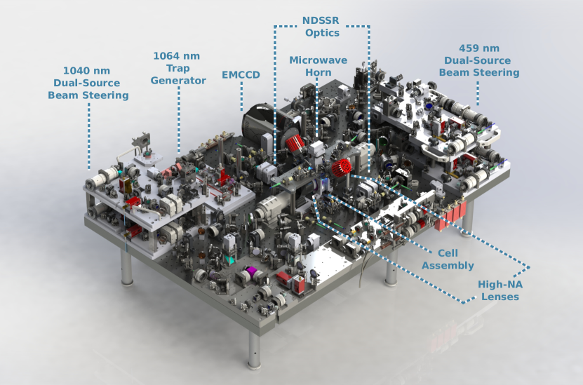
At the core of our platform, the qubit array is housed in a custom Infleqtion-manufactured dual-chamber ultra-high-vacuum glass cell, which lives at the center of the Quantum Processing Unit (QPU, Fig. 5). From the lower chamber, a cold atomic beam is generated with a 2D magneto-optical-trap (MOT), which loads a 3D MOT in the upper chamber. Surrounding the upper chamber are components to stabilize the electric and magnetic field environment, as well as a 405 nm light source for inducing atom desorption from the cell walls, and a microwave horn for implementing GR gates (Sec 3). Large beams address the whole atom array for implementing the 3D MOT, polarization gradient cooling, Raman sideband cooling[61], readout, and optical pumping. A 2D array of 1064 nm traps is generated by a pair of acousto-optic deflectors (AODs). Rydberg excitation light is provided by 1040 nm and 459 nm lasers, both locked to a stable, high finesse reference cavity. The two-photon detuning from the atomic transition is actively stabilized using a ground-Rydberg Ramsey signal. For each Rydberg wavelength (1040 nm and 459 nm), separate pulse shapers (one each for control/target qubit) feed separate beam-steering modules. The pulse shapers consist of double-pass acousto-optic modulators (AOMs), optimized for fast rise times. The 1040 nm beamline additionally contains an electro-optic modulator (EOM) for implementing the phase modulation used for CZ gates. The beam steering modules each consist of a pair of AODs with orthogonal axes, for rastering to any location within the array. For each Rydberg wavelength, the control and target beams are combined on a non-polarizing beamsplitter. The 1040 nm light is combined with 1064 nm light and focused onto the atoms from one side of the cell, via high numerical aperture () objective lenses, while the 459 nm light is focused from the opposing side, using a matching high-NA lens. These lenses also collect atom fluorescence during readout and direct it to an electron-multiplying CCD camera (EMCCD). Atom-based beam profiling of the 1064 nm tweezer measured a Gaussian beam waist radius at of peak intensity of 1.4(2) ; beam waist estimates of 2.8 and 3 m for 459 nm and 1040 nm beams, respectively, are discussed in Sec. 2. The trap depth is calibrated by measuring the intensity dependence of the qubit microwave transition; for the benchmarking data presented in this work, the estimated trap depth is 1 mK. The QPU is enclosed for electromagnetic, thermal, and vibrational isolation and stabilization.
6.2 Cooling and state preparation
Here we give a brief description of how we cool atoms inside the optical trap and initialize them in the state. Once the atoms are loaded into the optical trap, we turn on a pair of counter-propagating beams on all three axes to provide polarization gradient cooling (PGC). The same beams are used for occupancy readout but at smaller detuning and different intensity balance. After PGC, the magnetic bias field is stepped from zero to approximately 6 G along the x-axis and a circularly polarized 895 nm laser optically pumps atoms to the stretched state . After 10 ms of optical pumping, we typically measure a temperature of using the release-and-recapture method. This is followed by a Raman sideband cooling (RSC) step[61], where optical pumping pulses and Raman pulses alternate. At the end of RSC, a sequence of composite microwave pulses transfers atoms from the stretched state to qubit state . After the microwave pulse sequence is complete, the magnetic bias field is rotated from 6 G along the x-axis to the final bias field of 11.15 G along the z-axis. Once the rotation is complete, a microwave pi pulse transfer the atoms from to , and this marks the beginning of a quantum circuit.
The quantum circuit shot rate data discussed in Sec. 6.8.3 used a different optical pumping method in which a linearly polarized 895 nm beam pumps atoms towards at 11 G.
6.3 Benchmarking of gates
We characterize our gates using interleaved randomized benchmarking (IRB), randomly sampling each gate over . Given the implementation of our gate, we expect a significant scattering error contribution due to off-resonant excitation to the state. This can produce leakage error that populates ground-state Zeeman sublevels outside the qubit manifold. In these states the fidelity with the target state is , in contrast with true depolarizing error with . Denoting this leakage probability as , and the depolarizing probability (conditioned on not experiencing a leakage error) as , we can express the probability per gate to implement the desired unitary as . With this definition, the data is then fit to , where is a fit parameter that accounts for reduced contrast arising from state preparation and measurement error.
We can express the fidelity :
| (1) |
Using and , this yields
| (2) |
The fidelity extracted from a given cycle polarization will thus depend on the ratio of depolarization to leakage. Since scattering error is well understood, we choose to model its contribution, and use this assumption in calculating the fidelity. We can predict the scattering error based only on the intermediate-state lifetime and detuning (). For the datasets presented in Fig. 2, we find:
| Fitted C | Modeled | Extracted | ||
|---|---|---|---|---|
| +885 MHz | 99.65(5)% | 0.125% | 0.11(3)% | 0.24(3)% |
| -2.1 GHz | 99.87(2)% | 0.066% | 0.03(1)% | 0.098(8)% |
We attribute the improved depolarizing error at GHz to improved laser intensity stability, and note a straightforward path to higher fidelity by further increasing intermediate-state detuning.
6.4 Calibration of CZ gates
CZ gate calibration proceeds in two phases. The first phase establishes AOM pulse parameters for resonant Rydberg excitation with the desired two-photon Rabi rate and component single-photon Rabi rates . Operationally, these single-photon rates are established by first setting the 459 nm laser power to give the desired differential light shift on the qubit, then varying the 1040 nm laser power to achieve the desired two-photon Rabi frequency. This is accomplished by iterated time/frequency-domain characterizations of Rydberg Rabi excitation. This calibration is executed sequentially on all qubits in the array in a single circuit, allowing parallelized calibration of all qubits.
The second phase calibrates the CZ gate pulse sequence, which consists of two components: a Rydberg pulse with sinusoidally modulated phase, followed by single-qubit phase corrections required to produce the canonical CZ gate. The uncorrected gate is calibrated first, by optimizing a cost function (Fig. 3b) that is insensitive to the single-qubit phases. The circuit begins and ends with gates, surrounding N pairs of CZ gates, with an gate interleaved within each pair. These interleaved gates provide the desired insensitivity to the single-qubit phases. A properly tuned gate results in all population returning to and detecting as bright-bright, while any dark signal indicates either a state or atom loss, both of which correspond to a gate imperfection.
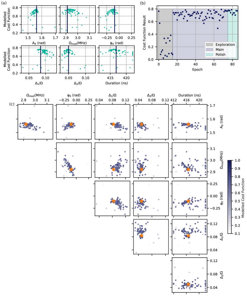
Using this cost function, we optimize a representation of the gate using six parameters: the amplitude (), frequency (), and phase offset () of the 1040 nm phase modulation, as well as the overall pulse duration and two-photon detuning. To compensate for calibration errors, we include separate two-photon detuning corrections for each qubit, though the protocol itself should be symmetric. To optimize these 6 parameters, we utilize a Bayesian optimizer (built on the BoTorch library) with a Gaussian process (GP) surrogate model. This allows us to optimize without making any assumptions about the underlying parameter landscape. Indeed, simulations suggest that our phase modulation waveform is somewhat over-parameterized, leading to the possibility of multiple local optima with similar performance. The optimizer run that preceded the benchmarking data from Fig. 3 in the main text is shown in Methods Fig. 6. In Methods Fig. 6b, we see the overall trajectory of the optimizer, over the course of 85 cost function evaluations, divided into an initial random sampling phase, a main exploration phase, and a final polish phase. Fig. 6a shows the final GP model, evaluated at the sampled parameter values, projected onto each parameter axis. The same data is shown in Fig. 6c, projected onto 2D slices of the space. This latter view can be useful for identifying correlations between parameters and finding improved parameterizations. Once an optimized waveform is identified (Fig. 3a), the single-qubit phases are measured via a qubit Ramsey sequence and appropriate corrections are determined.
6.5 Benchmarking of CZ gates
We compute the CZ fidelity from the results of our benchmarking circuits by measuring the probability of the circuits to produce the expected outcomes, which in this case are uniformly . In order to account for the possibility for each CZ gate to produce atom loss, leakage, or errors within the qubit subspace, we make use of the information afforded by our non-destructive state-selective readout capability (NDSSR, see Sec. 4). By sequentially performing NDSSR and occupancy measurements, we can determine whether a given atom was retained, and if retained, whether it was in the (bright signal) or (dark signal) ground-state manifold. We therefore separately analyze, to a gate depth of 20, the probability to retain both atoms () and the probability to observe a dark-dark measurement outcome in the state-selective measurement, given that both atoms were retained () (see Fig. 3). We fit these data to decaying exponentials with asymptotes of zero and one-quarter, respectively, and find a two-atom survival probability of % per gate and a cycle polarization of %. The observed cycle depolarization has contributions from true depolarizing error and from leakage to states . The former asymptotically produces the fully mixed state (with 25% fidelity with the target state), and the latter produces a state that has zero overlap with the desired state. A detailed model for the dynamics of the intermediate-state and Rydberg populations during the gate provides an estimated leakage probability of % per gate. We use this to calculate the CZ fidelity as , with the calculated probability of depolarizing error; we find a CZ fidelity of %.
The circuits we use to benchmark CZ gates consist of four steps: (a) preparation of the qubit state; (b) application of a variable number of gate pairs consisting of the same Haar-random SU(2) gate applied to both qubits, followed by a CZ gate; (c) an inversion operation consisting of alternated application of four global rotations and three CZ gates; and (d) another layer of Haar-random global SU(2) gates followed by a final inversion operation. Steps b-d in each circuit are constructed so that, in the absence of error, the circuit performs the identity operation on the input state. The final layer of random SU(2) gates is included to hold the total number of single-qubit gates constant at a value as the depth of layer (b) is varied. The data in Fig. 3 is a composite of two datasets, acquired concurrently, with 20 and 24; we verify that this composition does not introduce significant systematic error in the extracted fidelity by simulating the full benchmarking procedure (see Sec. 6.6). We calculate the inversion operation in step (c) as an alternating sequence of four CZ gates and four SU(2) gates, and then we omit the final CZ gate from the circuit because it does not change measurement outcomes. The structure of benchmarking circuits is depicted in Fig. 3a. The global SU(2) operations are implemented using a single global gate and an update to the qubit phase frame, which allows us to use only the global microwave field for the single-qubit gates in the CZ benchmarking circuits.
6.6 Simulation of CZ benchmarking
We conduct circuit-level simulations of our benchmarking procedure using a model for the CZ gate process. The error model includes transitions from the state to a loss state (no analogous term for the state is included, because only is near-resonantly coupled to the Rydberg state), as well as transitions between , , and ; the latter two states are leakage states that represent the and ground-state Zeeman sublevels and that are detected as and respectively. This model approximates spontaneous transition dynamics between the ground-state Zeeman sublevels, where a more complete model would separately treat all 16 ground states.
We calculate spontaneous transition probabilities, accounting for (a) interference between coupling of population from and from the Rydberg level to the intermediate state that produces “dark-intermediate-state” ground-Rydberg coupling [6], (b) interference in coupling paths through and , (c) the full decay chain from higher-lying decay products and , and (d) Rydberg decay-to-ground events. The result is a matrix describing the probability of a spontaneous transition per gate, expressed in the ordered basis:
| (3) |
Our error model includes these transition probabilities, as well as a probability per gate to transition from to of 0.39% and an additional single-qubit error probability of 0.065%. For a simulation of the circuits used to obtain the benchmarking data shown in Fig. 3, we find that this error model exactly reproduces the observed retention and polarization probabilities per gate. This validation is important because the true asymptote of the probability to observe the dark-dark outcome in the state-selective measurement is certainly different from 25%, accounting for the depumping from the hyperfine level driven by the 459 nm laser. We calculate the true gate fidelity, averaged over Haar-random input states, to be 99.38% for this error model. This is greater than and consistent with the 99.35(4)% fidelity extracted from the benchmarking data.
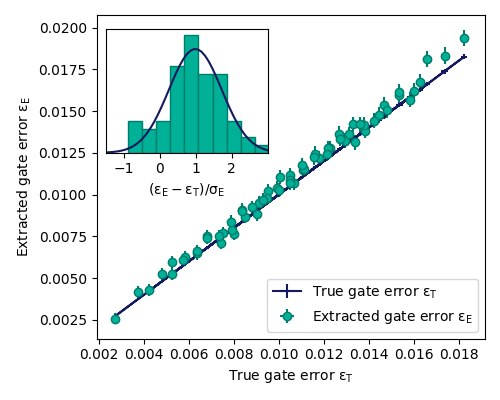
To further validate our benchmarking approach, we compare the true gate fidelity to the fidelity extracted from simulated benchmarking for a variety of error models. These models are obtained from the one thus far described by independently scaling the leakage matrix in Eq. 3, the probability, and the single-qubit dephasing probability. Benchmarking runs are simulated with the same number of circuits at each depth, and with the same , as used to obtain the data shown in Fig. 3, and the simulated analysis routine includes projection noise. Across these runs, the extracted error is larger than the true error in 86% of runs, with an average difference %. We present further quantitative details in Fig. 7.
6.7 Impact and mitigation of optical crosstalk in the scanned-beam addressing architecture
In our addressing geometry, the lasers that drive Rydberg excitation propagate perpendicular to and are focused in the plane of the atomic qubit array, across which their foci are scanned using acousto-optic deflectors. System level performance considerations (e.g. increasing qubit count and connectivity) exert pressure to reduce spacing in atom arrays. While in principle addressing beams’ spatial profiles can be shaped to effectively eliminate intensity on non-target atoms (which we refer to as “crosstalk”), in practice crosstalk elimination is challenging over large optical field of view, for optical systems consisting of many optical surfaces, and for atom separations that approach the optical wavelength. For example, given our 6 m qubit spacing and 3 m Rydberg beam waists, one predicts an intensity crosstalk of %, and in practice atomic measurements suggest up to 10 times larger in the worst case, likely due to the impact of wavefront distortions introduced by optical surface imperfections. The practical inevitability of crosstalk motivates a discussion of two of its primary effects and their relevance to high-fidelity and fault-tolerant operation of our neutral-atom quantum processor.
6.7.1 Effect of optical crosstalk on entangling gate error
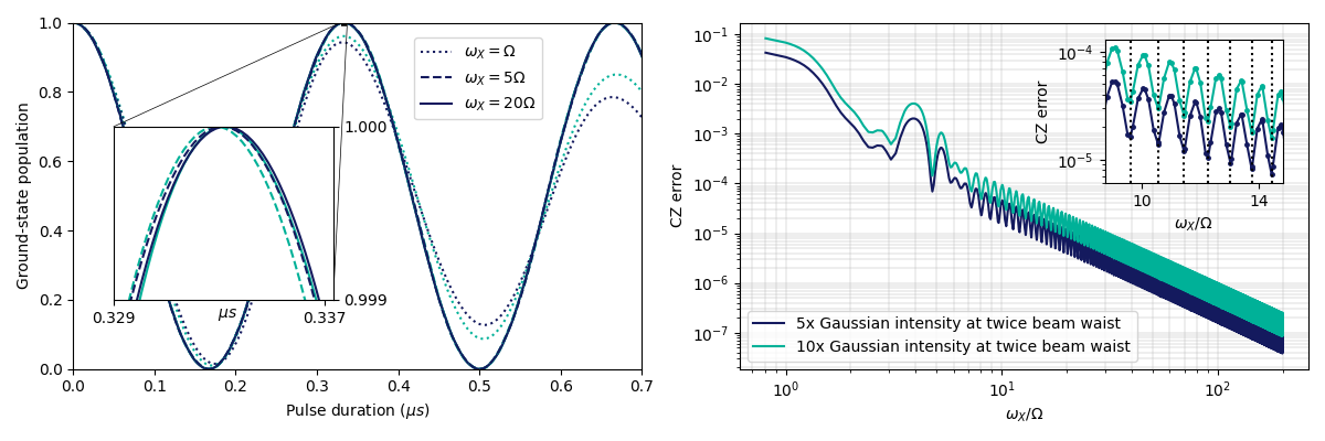
In an entangling gate multiple atoms are addressed by different fields, and crosstalk error contributions fundamentally arise due to the interference between the direct addressing field and the crosstalk field on each atom. If this interference can be compensated, for example by appropriately modulating the intensities of the fields, then the error contribution vanishes. However, such compensation presents a challenging control problem, suggesting that a different solution is more promising: we take an approach where the frequency of this interference can be made much larger than the Rabi frequency describing the gate dynamics. Simulations confirm that as the ratio increases, the Rabi dynamics average over this increasingly fast perturbation, allowing the desired gate dynamics to be realized. They also reveal that achieving a ratio of of about 50 is sufficient, for the particular crosstalk intensities we investigate, to make the CZ error contribution from optical crosstalk negligible compared to error correction thresholds. Our system currently operates at , but with modifications to the frequency/diffraction-order of the pulse shaping AOMs, it is straightforward to reach . This modeling suggests that maintaining a sufficiently large beatnote between neighboring addressing beams is a straightforward and effective way to mitigate crosstalk in an individual-addressing architecture. However, alternative mitigation strategies exist, including operation at zero beatnote frequency with active or passive stabilization of the relative phase between the two beams.
We depict simulations of the impact of optical crosstalk on single-atom Rabi oscillations to the Rydberg state and on CZ error in Fig. 8.
6.7.2 Effect of optical crosstalk on spectator qubits
During implementation of an or CZ gate, the addressing lasers irradiate spectator qubits with some small crosstalk intensity. In the case of an gate, crosstalk from the 459 nm laser produces an unintended gate on spectator qubits, where for relative crosstalk intensity . The realized rotation implements the desired identity operation on the spectator qubit with an expected error for a Haar-random input spectator state. This error is quadratic in the crosstalk intensity . As an example, if we take as an approximate description of our current system, for we have .
In the case of a CZ gate, the 459 nm laser applies a similar undesired rotation to spectator qubits. For our current parameters, the rotation applied to a spectator qubit by a CZ gate is equivalent to that from an gate on the target qubit, for which we calculate for .
The impact of these spectator-qubit rotations on overall circuit fidelity is circuit dependent. We estimate the impact using simple assumptions: that every qubit is targeted by the same number of gates, and that every nearest-neighbor pair is targeted by the same number of CZ gates. We calculate an effective adjustment to the fidelities of the and CZ gates on a given atom by including error accumulated during other and CZ gates in which that atom is a nearest-neighbor spectator. In a square lattice under this assumption, the ratio of nearest-neighbor-spectator/target rotations a given qubit experiences is 4, while for CZ gates this ratio is 3. We can therefore add an effective, heuristic error contribution to the gate error budget of . To the CZ gate error budget we add an analogous , where the first factor of 2 arises from the number of qubits participating in the gate. This suggests that reducing the crosstalk intensity may be important for future fault-tolerant operation, but a more complete analysis should calculate the circuit-specific impact. Another possibility that should be explored is crosstalk-aware compilation [33], in which the native gate set contains gates not of the form , but instead and similar for the CZ gate.
There are two more effects arising from the CZ gate that we consider: Compared to the 459 nm beam, the differential qubit shift from the 1040 nm Rydberg-excitation beam is smaller by a factor larger than , so we neglect the very small rotation applied by the 1040 nm crosstalk. Finally, coupling to the Rydberg level may arise from illumination by 1040 nm crosstalk and 459 nm crosstalk. If we assume the same relative crosstalk intensity for both colors, the Rabi frequency of this coupling is , where is the Rabi frequency for the target qubit. Additionally, the spectator atom’s ground-to-Rydberg transition frequency differs from the target atom’s by (approximately) the value of the light shifts applied to that transition by the Rydberg excitation beams. This produces a ground-to-Rydberg coupling on the spectator atom that is (a) weaker by a factor of and (b) very far detuned. Concretely, for our current system parameters and , we estimate that this coupling is relatively detuned by an amount . The time-averaged spectator-qubit population in the Rydberg state arising from this coupling is ; we therefore fully neglect this effect as well.
6.8 NDSSR implementation
6.8.1 NDSSR sequence and optimization
Our implementation of non-destructive state-selective readout improves upon the setup demonstrated in [41]. At the end of circuit execution, the bias field is rotated from the z-axis to the x-axis (see Fig. 1c for orientation) along which two counter-propagating, circularly-polarized, near-resonant 852 nm beams optically pump atoms in the upper hyperfine manifold to the stretched state and scatter photons primarily along the closed transition . The beams are red-detuned from zero-field resonance by MHz, with one beam further detuned by kHz to wash out the standing-wave intensity pattern; the peak beam intensity per beam is estimated to be , which is close to the saturation intensity of the transition (1.1 ). Atoms that are in the lower hyperfine manifold stay dark during this process. The intensities of the near-resonant beam-pair and the trap laser are modulated out-of-phase, so that the trap laser intensity is minimized while the atoms have a high probability of being excited by the imaging beams. The trap intensity modulation has a nominal duty cycle of 75% and the imaging beam pair has a nominal duty cycle of 15%. The duty cycle and the phase offset of the intensity modulation waveforms are controlled by the DDS cards driving the acousto-optic modulators for the lasers. Because there is no three-dimensional cooling, with only Doppler cooling expected on the imaging beam axis, atom temperature quickly rises during this readout and hence exposure time has to be limited such that atom loss from the trap is minimized while achieving good discrimination between bright and dark distributions of the camera signal. Exposure time of 6 ms was found to be sufficient to provide high bright-dark discrimination fidelity (99.6(2)%). By carefully optimizing the laser power modulation parameters, power balance between counter-propagating beams, and the bias field, we were able to achieve state-average atom-loss probability of % ( Fig. 4b) in a time-averaged trap depth of 1.97 mK (peak trap depth 2.6 mK), which is significantly lower than mK used in [41] and [62] while achieving better atom loss rate. Preliminary results of further optimization and technical improvements not discussed in this work suggest that the peak trap depth can be lowered to 2 mK while maintaining the state discrimination fidelity and atom loss rate mentioned in Sec. 4. In particular, we observed an interesting correlation between the optimal intensity modulation frequency for minimal atom loss and the Zeeman energy difference between levels of the upper-hyperfine manifold, which warrants further investigation; for the readout sequence used in this work, we chose a x-bias field of 3.59 G and intensity modulation frequency of 1.32 MHz. Leakage of off-resonant repump laser light due to the finite extinction ratio of acousto-optic switches can result in increased dark-to-bright state leakage at deep trap depths, which accounts for some of the 1.6(5)% dark state discrimination error mentioned in Sec. 4.
6.8.2 Discrimination fidelity modeling
We define discrimination fidelity as the probability of correctly classifying the photo-electron counts as coming from atomic fluorescence. For each qubit trapping site, we define a mask for selecting relevant camera pixels and then compute a weighted sum of raw camera analog-digital units (ADU) for those pixels (note each pixel has a fixed offset, which must be subtracted); the sum is then converted into photo-electron counts by dividing the sum by the EM gain (300) and then multiplying by the pre-amplifier gain (5.16 electrons per ADU count) provided by the EMCCD vendor datasheet. We model the distribution of photo-electron counts as a mixture of two distributions: exponentially modified Gaussian for the dark distribution weighted by the dark counts fraction , and skew-normal for the bright distribution weighted by the bright counts fraction :
| (4) | ||||
| (5) | ||||
| (6) |
The dark distribution is parametrized by , , and , which describe the location, scale, and shape of the dark distribution, respectively. The bright distribution is parametrized by , , and , which describe the location, scale, and shape of the bright distribution, respectively; and are the error function and the complementary error function. We obtained the following parameter values after fitting the proposed mixture distribution to the SPAM image dataset used in Fig. 4: (see Fig. 9a for the fit plot). Regarding the choice of using exponentially modified Gaussian distribution for the dark distribution, we believe that a convolution of normal and Gamma distributions is more appropriate, based on the observation that the EMCCD ADU count per pixel distribution in the dark can be modeled as a mixture of normal (from readout noise) and Erlang distributions (from parallel clock-induced charge noise) [63], but we found that exponentially modified Gaussian distribution fits the data just as well and is easier to compute; skew-normal distribution is chosen for the the bright distribution for a similar reason of convenience.
Once a mixture distribution is fitted to the data, the optimal discrimination threshold is then determined as the photo-electron count minimizes the sum of classification errors , which is
| (7) |
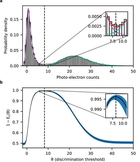
To estimate the discrimination fidelity using this model, we applied bootstrapping to the SPAM image dataset used in Fig. 4: we created 1000 SPAM image subsets, with each subset containing 2000 images randomly sampled from the main dataset with replacement, fit the mixture distribution for the photo-electron counts in each subset and then computed . The bootstrapping result (Fig. 9b) shows that the discrimination fidelity saturates at 99.6% around the discrimination threshold of 8.29 photo-electron counts.
6.8.3 Shot rate enhancement from repetitive measurements
In our architecture, a measurement cycle is defined by a sequence of repetitive measurements that continues until the maximum measurements allowed per cycle is reached or the atom reservoir is depleted. The shot rate enhancement effect of repetitive measurement was measured by averaging the total execution times of a quantum circuit that prepares a 15-qubit GHZ state with CZ gates for entangling, local gate for qubit phase correction and global gates for applying Hadamard and dynamical decoupling gates. The test circuit consisted of 14 CZ gates, 14 gates and 29 gates. The circuit was repeated three times with each instance requiring at least 400 valid measurements and maximum measurements per measurement cycle limited to seven, and recorded total execution times of 47.7 s, 50.3 s, and 48.1 s which results in an average shot rate of 8.2(2) Hz. In this context, a raw measurement is invalidated if the post-NDSSR occupancy measurement detected an atom loss in the qubit array, and multiple measurements in a measurement cycle are invalidated if analog (laser intensity) and digital (laser lock status) validators detected samples out of validation bounds at the end of a cycle; the total execution time is defined by the time interval between the beginning of pulse sequence compilation and control device initialization and the end of the job data (camera image set) upload to the database. It should be noted that this data was taken when the CZ gate fidelity was significantly lower (average SPAM-corrected Bell state preparation fidelity was 93.1%) than the best CZ gate fidelity demonstrated in this work and the NDSSR bright state atom loss rate was slightly higher (% instead of 1%), resulting in higher atom loss and incurring more measurement invalidation and atom loading and arrangement iterations. We did not repeat the circuit execution for maximum one measurements per measurement cycle, but null circuit (empty circuit) measurements on the same day suggests the shot rate would have been limited to 3.2 Hz even in the absence of gate-induced atom loss.
6.9 Acknowledgements
We gratefully acknowledge contributions from Alan Doak, Alex Olivas, Brenden Villars, Bryna Guriel, Cody Mart, Chris Wood, David Owusu-Antwi, Denny Dahl, Emma Brann, Evan Salim, Jan Preusser, Jean-Philippe Feve, John Sivak, Jonathan Cohen, Jorge Gomez, Josh Behne, Josh Cherek, Karen Rosenthall, Marie Grubb, Marissa McMaster, Matt Ebert, Rob Williamson, Robin Keus, Ryan Prior, Salahedeen Issa, Stephanie Lee, Steven Kitchen, and Steven Sedig.
6.10 Author contributions
AGR, DM, TWN, WCC, DMG, AMS, DCC, MCG, MTL, GTH, ILB, TO, EC, MS, MY, SDS, AJF, RAJ, KWK, FM, IVV, MLW, MI, PTM, JRT, MKD, JRG, MRB, JKM, AR, and TMG contributed to the design and construction of the apparatus hardware, AGR, DM, TWN, WCC, AMS, NGP, DCC, TGB, MTL, GTH, DG, ILB, TBL, CC, PG, VO, PG, EC, MJB, MEB, AKT, EBJ, RAJ, KWK, SYE, DAB, CPS, IVV, JJM, PTM, JRT, MKD, JRG, NANM, CJGJ, PJR, LLH, PDB, RR, and MAP contributed to the control system and software stack. AGR, DM, TWN, WCC, DCC, MTL, GTH, CC, PG, VO, EC, EBJ, RAJ, KWK, IVV, PTM, JRT, MKD, and JRG contributed to operating the apparatus and collecting the data. AGR, DM, TWN, WCC, DMG, DCC, MTL, GTH, ILB, CC, PG, VO, TO, PG, JMG, EC, MS, EBJ, JDM, RAJ, KWK, IVV, JAM, PTM, JRT, MKD, JRG, NANM, AC, TMG contributed to analysing data, AGR, DM, TWN, WCC, DCC, MTL, GTH, CC, EC, MS, MY, EBJ, JDM, KWK, IVV, JRT, JRG, RR, TMG, and MAP contributed to theoretical analysis and simulation. The manuscript was written by AGR, DM, TWN, WCC, DCC, and MS. The project was supervised by AGR, TWN, WCC, DCC, DG, PG, TO, MEB, MS, JJM, and MI.
6.11 Data availability
The data presented here are available from the corresponding author on reasonable request.
6.12 Competing interests
AGR, DM, TWN, WCC, DMG, AMS, NGP, DCC, MCG, TGB, MTL, GTH, DG, ILB, TBL, CC, PG, VO, TO, PG, JMG, EC, MJB, MEB, MS, AKT, MY, SDS, EBJ, AJF, JDM, RAJ, KWK, SYE, DAB, FM, CPS, IVV, JJM, MLW, JAM, MI, PTM, JRT, MKD, JRG, NANM, MRB, CJGJ, PJR, JKM, AR, LLH, PDB, RR, AC, MAP are employees and/or shareholders of ColdQuanta, Inc d.b.a. Infleqtion.