A Room-Temperature Solid-State Maser Amplifier
Abstract
Masers once represented the state-of-the-art in low noise microwave amplification technology, but eventually became obsolete due to their need for cryogenic cooling. Masers based on solid-state spin systems perform most effectively as amplifiers, since they provide a large density of spins and can therefore operate at relatively high powers. Whilst solid-state masers oscillators have been demonstrated at room temperature, continuous-wave amplification in these systems has only ever been realized at cryogenic temperatures. Here we report on a continuous-wave solid-state maser amplifier operating at room temperature. We achieve this feat using a practical setup that includes an ensemble of nitrogen-vacancy center spins in a diamond crystal, a strong permanent magnet and simple laser diode. We describe important amplifier characteristics including gain, bandwidth, compression power and noise temperature and discuss the prospects of realizing a room-temperature near-quantum-noise-limited amplifier with this system. Finally, we show that in a different mode of operation the spins can be used to cool the system noise in an external circuit to cryogenic levels, all without the requirement for physical cooling.
I Introduction
The detection of weak microwave signals is a challenge that lies at the heart of many modern technologies, including deep-space satellite communication systems [1], radio telescopes [2], radar and electron spin resonance (ESR) spectrometers [3]. The Voyager 1 space probe transmits microwave signals at a power of approximately 20 W, reducing to a mere W of power by the time the transmissions reach Earth [4]. In order to detect such faint signals, microwave receivers must add as little noise as possible, taking advantage of ultra-low noise amplifiers to first boost the signals before measurement.
Maser amplifiers are devices that exploit stimulated emission in an inverted ensemble of microwave-frequency emitters – often in the form of paramagnetic centers such as spins – to achieve low-noise amplification of microwave signals. The noise temperature of a maser amplifier , which quantifies the amount of noise added to a signal before it is amplified, can theoretically reach the quantum limit of , where is the spin transition frequency and and are the reduced Planck and Boltzmann constants, respectively. For a maser operating in the microwave X-band ( GHz), this temperature can be as low as K.
Maser amplifiers based on solid-state spin systems such as ruby [5] once represented the gold-standard in low-noise microwave amplification technology. The requirement for solid-state maser amplifiers to be cooled to cryogenic temperatures (typically K) [6] saw these systems eventually replaced by modern transistor-based amplifiers [7]. However, pioneering experiments using organic [8] or diamond-based [9] spin systems have demonstrated that solid-state masers can operate at room temperature, generating a resurgence in their interest. Due to the tantalizing prospect of achieving quantum-limited noise performance, there has been a renewed effort [10, 11, 12, 13, 14] to develop room-temperature solid-state maser amplifiers.
Maser amplification of short (s) pulsed microwave signals was recently observed at room temperature using a spin system in an orgnic host [13], whilst a continuously operating diamond maser amplifier was realized at liquid nitrogen temperatures ( K) [12]. However, the demonstration of a widely usable continuous-wave maser amplifier operating under ambient conditions remains a highly desirable objective.
In this work we describe a continuous-wave maser amplifier based on a solid-state system that operates at room temperature. We use an ensemble of nitrogen-vacancy (NV) center spins in a bulk diamond crystal as the gain medium and couple this to a high quality factor microwave dielectric resonator. We achieve gains as high as 30 dB and a gain-bandwidth-product of up to 4.5 MHz. Our analysis shows that the intrinsic noise temperature of the spin gain medium is close to the quantum limit, whilst the dominant source of noise comes from resonator losses. We further demonstrate that the same device can be used to remove microwave noise in a circuit [16, 17, 18, 19] by acting like a matched load with an effective microwave temperature of 66 K, without the need for any cryogenic cooling. We develop a modern quantum optics theoretical model [20] to describe the maser amplifier and microwave cooler system and obtain quantitative agreement with our measurement results. Finally, we discuss relatively straight-forward improvements that can be made to our system to push its noise performance towards the quantum limit. These results demonstrate that NV spin ensembles in diamond coupled to microwave resonators constitute a system with exceptional promise for performing ultra-low noise detection of microwave signals at room temperature.
II Results
II.1 Maser amplifier design
Solid-state masers have been realized at room temperature using several different physical spin systems, including organic crystals of pentacene doped in para-terphenyl (Pc:PTP) [8] or 6,13-diazapentacene-doped para-terphenyl (DAP:PTP) [21] and diamonds containing negatively charged nitrogen vacancy (NV-) centers [22, 9, 23]. In each case the spin system was coupled to a high quality factor microwave dielectric resonator and population inversion of the spins was achieved via optical pumping using moderate [9] or high power [8] lasers. Diamond is an ideal material for hosting the gain medium due to its high thermal conductivity (2,200 Wm-1K-1 at 294 K) [24], which allows any heat generated by the optical pumping to be rapidly dissipated in its surroundings.
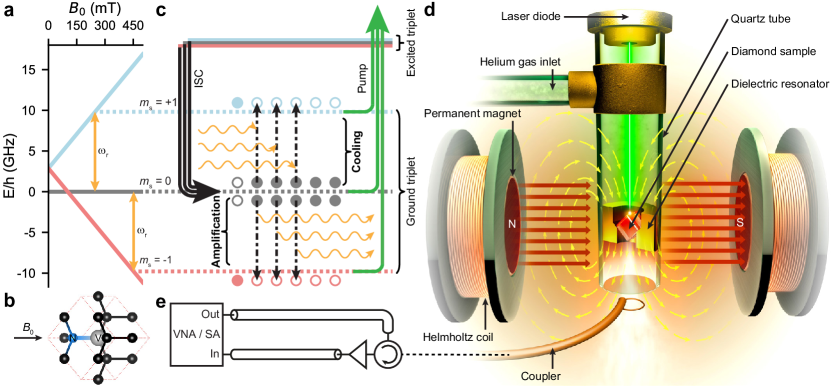
In this work we utilize a high concentration NV- diamond bulk crystal as the gain medium. The energy level structure of the NV- triplet ground state is shown in Fig. 1a. When a static magnetic field is applied parallel to one of the four equivalent NV directions (see Fig. 1b), the states of the NV- spins Zeeman split with a gradient of (with GHz/T), offset by a zero field splitting of GHz [25, 26]. The NV- spins can be readily polarized into the ground triplet state by optical pumping using green ( 520 nm) light. At a sufficiently large , the spin state energy falls below that of the the state and the optical pumping results in a population inversion [9] (see Fig. 1c, lower), fulfilling a key condition for implementing a maser amplifier. For smaller fields where the state is lowest in energy (see Fig. 1c, upper), the NV- spins absorb microwaves and can thus be used to reduce the noise present in a circuit [16, 17, 18, 19].
Figure 1d depicts the setup utilized in our work. The diamond sample employed is a rectangular prism of dimensions 1.8 mm 1.9 mm 2.0 mm and is grown by chemical vapor deposition (CVD) with faces. It has a nominal concentration of ppm NV-, as specified by the manufacturer (see Methods). The diamond prism is positioned inside a cylindrical dielectric resonator that is custom-made from a high-permittivity () ceramic material, which exhibits a fundamental microwave mode in the microwave X-band at GHz (see Supplementary Information, Section LABEL:sup:subsec:DR for details). The resonator contains a sloped inner lip to support the diamond and ensure that the field can be aligned along one of the directions of the crystal. The high permittivity of the ceramic dielectric material reduces the resonator volume for a given frequency and thus enhances the interaction strength between the mode and the spins, which is particularly important when the diamond sample is smaller than the volume of the mode’s magnetic field (see Supplementary Information, Section LABEL:sup:subsec:DR). An adjustable inductive loop (see Methods) is used to couple the resonator to external circuitry (see Fig. 1e), with an external coupling quality factor () that can be made smaller or larger than the resonator’s internal quality factor (), which has a nominal value of .
To access the maser amplification regime using the NV system, a field of approximately 450 mT must be applied to bring the to spin transition frequency to GHz. The generation of such a strong magnetic field is typically achieved using large and high power consumption electromagnets [9, 23], which present challenges for the ultimate goal of creating a low size, weight and power amplifier. In this work, the magnetic field is provided by a permanent magnet, with a small electromagnetic Helmholtz sweep coil to allow fine tuning of the field (see Methods). The green pump laser is supplied by a simple 1.5 W optical output power laser diode, which is less expensive, has a relatively low power consumption and a small form factor compared to other pump lasers.
Our ceramic resonator has a low thermal conductivity (2.56 Wm-1K-1 at 294 K), which prevents adequate heat dissipation and causes both the diamond and resonator temperature to rise during optical pumping. Since the spin relaxation time (and therefore our ability to optically pump the NV- spins) depends strongly on temperature [23], maintaining the diamond sample at room temperature is vital. Further, increasing the resonator temperature leads to higher levels of thermal noise, which is also to be avoided. To better thermalize the diamond and resonator assembly, we flow room-temperature helium gas – which has a thermal conductivity of 0.15 Wm-1K-1 at 294 K, approximately a factor greater than air – continuously over the sample (see Fig. 1a). This maintains both the resonator and diamond close to room temperature, even when operating the laser diode at full power, as verified by probing the resonator noise and performing spin measurements (see Supplementary Information, Sections LABEL:sup:subsec:He and LABEL:sup:subsec:T1T2). With helium gas applied, the spin time for our sample is ms (see Supplementary Information, Section LABEL:sup:subsec:T1T2).
II.2 Input-output model
The theory describing gain and noise in maser and other types of negative resistance amplifiers was established over six decades ago [6]. These theories use a semi-classical wave-approach analysis based on simple thermodynamic arguments. Here we develop a quantum optics theoretical model for our system which takes into account microscopic details of the spin gain medium and relates important quantities like gain and noise to modern circuit quantum electrodynamics parameters [27]. In doing so, we are able to describe the full frequency dependence of the reflection and noise spectra when operating the system in either the maser amplification or microwave cooling regimes. In Sections II.3.1 and II.3.3 we show that the model reproduces key predictions of the semi-classical theory. Our model is based on the input-output formalism of Gardiner and Collett [20] and builds on previous input-output descriptions of resonators coupled with inverted [28] or non-inverted [29, 30, 18, 31] spin ensembles. A full derivation of the model is presented in the Supplementary Information (Section LABEL:sup:sec:Theory), below we summarize the key points and predictions.
Without damping, the system can be described by the following Hamiltonian:
| (1) |
where () is the annihilation (creation) operator for the resonator mode, , and are, respectively, the Pauli Z, raising and lowering operators describing the -th spin in the ensemble (out of total spins), which has a resonance frequency of and is coupled with a strength to the resonator. The distribution of spin frequencies is free to take any form here, with Lorentzian and Gaussian profiles being common.
Damping is introduced by coupling the resonator mode to (i) bath modes in the external cable, which carries input and output fields that couple to the resonator field at a rate , and (ii) bath modes representing any internal sources of resonator loss, which are coupled to the resonator field at a rate . Each spin is assumed to couple to an independent bath at a rate , which is at the effective spin temperature . We note that is negative for an inverted spin ensemble and positive for a non-inverted ensemble (see Supplementary Information, Section LABEL:sup:subsec:baths), relevant for the maser amplification and microwave cooling regimes, respectively. Figure 2 presents a summary of the various elements and interactions present in the system, as well as the sources of damping.
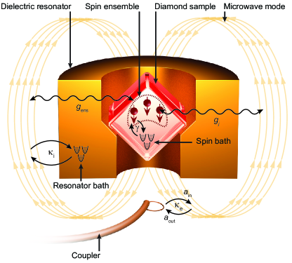
When probing the system with a microwave tone and measuring the reflected signal via the loop coupler (see Figs. 1d,e), the model predicts a reflection coefficient:
| (2) |
where , is a function that contains information about the spin resonance frequency distribution and their coupling to the resonator [29, 32], and the in the denominator indicates the solution for an inverted () or non-inverted () ensemble. For a spin ensemble with a Lorentzian distribution of resonance frequencies , one can show [29, 30]:
| (3) |
where is the collective coupling strength of the spin ensemble to the resonator, is the average spin resonance frequency and is the characteristic width of the spin frequency distribution. In the Supplementary Information (Section LABEL:sup:sec:kc) we also present an analytical expression of for a Gaussian spin distribution, however, can be numerically evaluated for any profile.
We are also able to predict the output noise spectrum of the system:
| (4) |
with,
| (5) | ||||
where is the frequency-dependent number of noise photons in the output field (i.e., traveling away from the resonator via the coupler), is the number of noise photons in the input field (traveling to the resonator via the coupler), is the number of noise photons in the spin bath, is the number of noise photons in the resonator loss bath and is a convolution function that depends on the details of the spin distribution (see Supplementary Information, Section LABEL:sup:sec:kc). We assume that the various baths are all in thermal states, with thermal photon populations given by the Bose-Einstein distribution , where is the effective temperature of the bath (see Supplementary Information, Section LABEL:sup:subsec:baths for details). Finally, we note that the terms in Eq. 4 correspond to the quantum limit of noise (vacuum fluctuations) introduced by each bath.
II.3 Maser amplifier performance
II.3.1 Gain
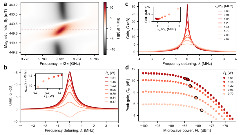
We proceed to operate the system as a maser amplifier by pumping the NV- spins with the laser diode at a power of W, whilst simultaneously probing the system using a vector network analyzer (VNA), allowing us to measure the reflection coefficient (Eq. 2). We adjust the position of the permanent magnet poles to provide a field close to mT, which brings the to spin transition near resonance with the dielectric resonator. We perform a fine sweep of the field using the Helmholtz coil and plot the power gain as a function of in Fig. 3a. Away from resonance with the spins, we observe observe a dip in at , which is due to the internal resonator losses. As the spins come into resonance with the resonator, they add energy to the system via stimulated emission, which compensates the internal losses in the resonator and transforms the dip in to a peak, signalling gain. We find a single gain peak, rather than the three that would be expected due to the hyperfine coupling of the NV- electronic spin with the nitrogen nuclear spin () [26]. This is due to the inhomogeneity of the field supplied by the permanent magnet at the given pole separation, which broadens the spin transition and produces a Gaussian-like profile (see Supplementary Information, Section LABEL:sup:subsec:spectra).
We fix at the center of the gain feature in Fig. 3a (indicated by the dashed line) and study the effect of the optical power on the maser amplifier gain (Fig. 3b). At the lowest power applied W, the stimulated emission from the spins is not sufficient to overcome the cavity losses, however, as is increased we observe rising levels of gain. By fitting the gain curves in Fig. 3b with our theoretical model (Eq. 2), where we use independent measurements to tightly constrain some of the parameters (see Methods), we are able to extract the ensemble coupling strength as a function of (inset Fig. 3b), which reaches a maximum of MHz at W.
We can write down an expression for the peak maser gain (which occurs at resonance ) using Eq. 2:
| (6) |
where we have defined a new parameter that describes the emission (absorption) rate of photons to (from) the resonator by the spin ensemble. The spin distribution effective width is in general a function of both and (e.g. for a Lorentzian distribution ) and is discussed in the Supplementary Information (Section LABEL:sup:sec:kc). We note that this expression is identical to the one obtained by performing a conventional wave-approach analysis of a maser amplifier [6, 33].
As is increased we produce higher levels of spin polarization and larger values of (inset Fig. 3b), which raises the emission rate . Inspecting Eq. 6 we can see that as (controlled by ) approaches the total resonator loss rate , the peak maser gain is expected to increase, as observed in our data (Fig. 3b). However, for the system reaches an instability point which defines the onset of maser oscillations [22, 9]. This regime is undesirable for operating the system as an amplifier.
The maser is a negative resistance amplifier which exhibits a fixed gain-bandwidth-product (GBP) [34]. We can trade peak gain for bandwidth by adjusting the external coupling rate (see Fig. 3c), which is controlled via the position of the loop coupler. We observe up to 30 dB of gain at small bandwidths and find the GBP varies between MHz over the range of explored here (see Fig. 3c inset).
II.3.2 Compression power
A key metric for an amplifier is its 1 dB compression point , which describes the signal power at which the gain reduces by 1 dB, and is a useful measure of the linear operating range of the amplifier. We measure by sweeping the input microwave signal power while monitoring the maser gain. Figure 3d shows the peak gain versus for different laser powers . We find a constant compression power of dBm (signal power at the output of the maser amplifier) over the range of gains explored. This corresponds to a projected -93.9 dBm of input power at 20 dB of gain, which is 20-30 dB higher than quantum-limited Josephson junction amplifiers [35, 36, 37], but smaller than kinetic inductance based superconducting quantum-limited amplifiers [38] and about 10 dB below the recently demonstrated cryogenic NV maser amplifier [12]. While the current performance is likely sufficient for applications that work with ultra-faint signals like deep space satellite communication [1], for others, including spin resonance spectroscopy, it would be beneficial to raise the . In Section III we discuss modifications to the system that could be made to push the compression power to higher levels.
II.3.3 Noise temperature
We evaluate the maser amplifier’s noise temperature by utilizing a protocol based on the cold source measurement technique [39, 40]. The setup (depicted in Fig. 1e) includes a spectrum analyzer (SA) or VNA connected to the maser system via a microwave circulator. A low-noise transistor amplifier boosts the output of the maser before detection. Through precise measurement of the transistor amplifier’s noise temperature, the insertion loss of the system components, as well as the maser amplifier’s output noise power and gain, we are able to extract the intrinsic noise temperature of the maser system (see Methods and Supplementary Information, Section LABEL:sup:sec:noise).
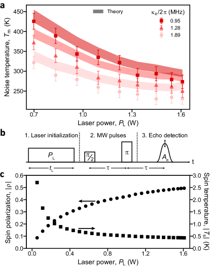
Figure 4a shows the extracted maser amplifier noise temperature (referred to its input) versus laser power for different values of the external coupling rate . As is increased, all datasets demonstrate a reduction in the noise temperature. In addition, we observe that increasing also reduces the noise temperature. We find a minimum noise temperature of K for MHz, where the maser gain is 6.5 dB. To understand this behavior, we consider our theoretical expression for the output noise (Eq. 4). The output noise contains three contributions, amplified noise from the input field, amplified noise from the spins and amplified noise from the resonator losses. The first component is not intrinsic to the amplifier and is subtracted in our measurements, whilst the remaining two contributions dictate the maser noise temperature.
To provide an intuition as to how the various parameters affect the noise, we define a new quantity which is the input-referred maser amplifier noise (i.e. the maser’s output noise divided by its gain). At resonance () becomes:
| (7) |
where,
| (8) | ||||
Once again, we find that the simplified expressions in Eqs. 7 and 8 agree exactly with those obtained from a simple wave-approach analysis of a negative resistance amplifier [6, 33]. It is evident from Eq. 8 that both components of reduce with increasing (and hence ) and also with increasing , as seen in our measurements. We note, however, that whilst increasing enhances the gain and reduces noise, increasing (at a fixed ) reduces the noise at the expense of lowering the gain (see Eq. 6).
To make theoretical predictions of , we extract the parameters , , and at each data point in Fig. 4a from independent measurements (see Methods) and assume that the resonator bath is at the physical temperature of the resonator ( K). We estimate the spin bath occupation from measurements of the effective spin temperature, as detailed below. We then convert to an effective temperature by inverting the Bose-Einstein relation , allowing us to predict the range of noise temperatures expected in Fig. 4a (shaded regions) from uncertainties in the model parameters. We find good agreement overall, with all theoretical predictions residing within 15% of the measured temperatures.
To examine the limits of noise in a maser amplifier, we take the extreme case of a lossless resonator () with a spin bath at zero temperature (). We see that for large gain () the maser noise approaches the quantum limit for a phase-preserving amplifier [41], i.e. , corresponding to a temperature . However, for imperfect optical pumping, the effective spin temperature is non-zero. The spin temperature is defined by the spin polarization , which is given as:
| (9) |
The spin polarization in our system is determined by optical pumping, where , with () representing the population of the () spin state. Since , the spin temperature at the maser amplification transition is negative.
We determine (and thus ) in our device by performing Hahn echo measurements using the protocol depicted in Fig. 4b. The sequence starts with a spin initialization phase, where the diamond is exposed to light at a power for a duration of ms. Following this, a Hahn echo pulse sequence is delivered to the spins and the resulting spin echo signal is recorded in a final step. We find the amplitude of the spin echo , which is proportional to [3]. When W (no optical initialization), the the spins are in thermal equilibrium at room temperature ( K) and can be determined from Eq. 9 by setting . Taking this absolute value of , together with the ratio of echo amplitudes measured with the laser on versus the laser off, we are able to calculate and as a function of (see Supplementary Information, Section LABEL:sup:sec:spin_temp). We plot the resulting magnitudes of the spin polarization and the spin temperature in Fig. 4c.
For the largest applied, we achieve a maximum spin polarization of , corresponding to an effective spin temperature K. We therefore estimate the intrinsic noise contribution from the spin gain medium (first term in Eq. 7) to be between K for the range of explored in Fig. 4a at maximum laser power. The maser amplifier noise temperature is therefore almost entirely determined by resonator losses. In Section III we discuss viable pathways to reduce the noise originating from the resonator loss thermal bath.
II.4 Microwave cooling

Next we adjust the permanent magnet pole positions to set mT, bringing the to spin transition in resonance with the dielectric resonator. The NV- spins, which are now polarized in the ground state of this two-level subsystem, absorb microwave photons from the resonator (including thermal photons), which are then removed from the system via optical pumping. The removal of thermal noise photons lowers the effective microwave temperature of the mode [16, 17, 18, 19], which can be transferred to an external microwave circuit.
The noise emitted into the circuit by the microwave cooler can be found using Eq. 4, i.e. . At resonance (), we have:
| (10) | ||||
which determine the contributions to the cooler output noise from the input field, spin bath, and resonator losses, respectively. At resonance the cooler noise is minimized when the system is critically coupled . Under these conditions simplifies to:
| (11) |
which reduces as and grow relative to .
The system acts like a perfectly matched and cryogenically-cooled termination, which absorbs all of the room-temperature microwave noise from the input field (i.e., ) and emits cold noise at a temperature into the circuit.
To find the cooling spin transition we perform a fine sweep of whilst probing the resonator in reflection, with the result shown in Fig. 5a. We observe avoided crossings in the measured spectrum, which is indicative of strong coupling between the resonator and hyperfine transitions of the NV- spins [18]. We note that at this magnet pole separation we are able to partially resolve the hyperfine structure of the NV- system, indicating a higher field homogeneity than observed at the maser transition. Taking a line cut (dashed line in Fig. 5a) through the middle of this feature, we observe four dips in the magnitude response (see Fig. 5b, dark blue line), which are reproduced well with our model (see Eq. 2). A fit to the magnitude () and phase () reflection data allows us to extract the ensemble coupling strength , which is plot as an inset in Fig. 5b as a function of . We find excellent agreement with the extracted via the gain measurements in Section II.3.1.
To demonstrate cooling, we monitor the system noise using a SA with the setup depicted in Fig. 1e. We use a room-temperature low-noise high electron mobility transistor (HEMT) amplifier with a noise temperature of K (see Methods) to boost the system output above the noise floor of the SA. We fix at the center of the spin resonance feature and change the position of the loop coupler until the system is at critical coupling . In Fig. 5c we plot the the difference (in decibels) between two noise power measurements, (i) with the spins on resonance and the laser on, and (ii) with the spins off resonance (i.e., detuned) and the laser off. We see that for frequencies within the spin line width, the presence of the spins lowers the system noise by up to dB (i.e., a factor of ), corresponding to a system noise temperature of K at resonance (). Further, we find an average 2.8 dB of noise reduction over 5 MHz of bandwidth centered on . We predict the cooling performance of the system using Eq. 4, where we enter all parameters (extracted from independent measurements, see Methods) into the model and plot the result in Fig. 5c (solid black line). The model quantitatively reproduces the data without any free parameters.
We can calculate the cooler noise temperature by removing from the system noise any contribution due to insertion loss of the cables and components as well as the noise added by the HEMT amplifier (see Supplementary Information, Section LABEL:sup:sec:cooling). In Fig. 5d we plot the inferred as a function of the coupling ratio (left panel). As expected, the temperature reaches its lowest value at critical coupling . In the right panel of Fig. 5d we plot the cooler noise temperature versus laser power, ensuring that the system is critically coupled at each point. We find that reaches a minimum of K. Once again, our theory (light blue bands in Fig. 5d) is able to closely predict the noise performance of the microwave cooler for both experiments.
III Discussion
Our experiments have demonstrated a continuous-wave solid-state maser amplifier operating at room temperature. The system is made from simple components (such as a laser diode and permanent magnet) which could be translated to a small and portable form factor. Simply by adjusting the magnetic field we were able to switch to a mode where the system behaved as a cryogenically-cooled matched load, which emitted noise at a temperature of K into a microwave circuit. The measured noise temperature of our maser amplifier is comparable to current commercial general-purpose low-noise microwave amplifiers, but about a factor of 5 worse than state-of-the-art HEMT amplifiers. In addition, the GBP of the maser (up to MHz) currently only permits narrow band operation, with dB of gain over a MHz bandwidth. Whilst the current level of performance represents a promising first step, there are several avenues available to push its operation towards the quantum noise limit, extend the available bandwidth and improve its power handling capabilities.
The intrinsic noise generated by the spin gain medium ( K) was found to already be close to the quantum noise limit ( K), thus the main route to improve the noise performance is to reduce the contribution due to resonator losses (second term, Eq. 7). This can be achieved by decreasing and/or increasing – the latter also simultaneously improving the GBP. Alternative ceramics or low-loss dielectric crystals could be explored to produce resonators with higher internal quality factors . Increasing the concentration of NV- spins and/or the filling factor of the diamond sample inside the mode’s magnetic field would enhance and therefore (see Supplementary Information, Section LABEL:sup:subsec:DR). We estimate that doubling the NV- concentration from the current 3 ppm to 6 ppm and raising the internal quality factor from 10,000 to 20,000 would be sufficient to double the bandwidth and push the noise temperature below 30 K, surpassing the noise performance of the best commercially available room-temperature microwave X-band amplifiers. Such improvements are within reach. Increasing the concentration and therefore number of NV- spins would also directly enhance the compression power [22].
Looking further, we could improve the filling factor from the current 11% to 35% (i.e., a factor of ) by filling the entire center of the cylindrical dielectric resonator with NV diamond. We could also move from CVD to high pressure and high temperature (HPHT) grown diamonds, where higher NV- concentrations of up to 20 ppm are possible [19]. This could boost the GBP and by a factor of relative to the present demonstration, and together with a doubling of , lower the noise temperature to 4 K. One could utilize even lower loss sapphire dielectric resonators, with [9], pushing the noise temperature towards 1 K. However, the lower dielectric constant of sapphire () would increase the mode volume and require even larger diamond samples to maintain high filling factors, leading to increased laser powers and stricter requirements for thermal management.
The GBP could be enhanced even further by moving to travelling wave [42] or reflected wave [43] architectures, which eliminate resonators to increase the bandwidth. However, challenges in producing large volume high-concentration NV diamond samples might mean taking a hybrid approach between reflected wave and resonator designs, such as a multi-stage resonant amplifier [44], is more feasible.
The changes noted above would also serve to improve the achievable levels of microwave cooling. In the present setup, insertion loss ( dB between the device and the HEMT amplifier) limits the largest amount of noise reduction possible to 6.4 dB. This could be improved by transitioning from relatively lossy coaxial cables to waveguide technology [23]. By combining both maser amplification and microwave cooling in one experiment, one could ensure all components of the system noise are reduced, permitting the room-temperature detection of microwave signals with cryogenic-levels of noise.
This technology could one day replace cryogenically-cooled microwave receivers used for satellite communication in the deep space network [1], radio astronomy [2], or be utilized to permit high-sensitivity spin resonance spectroscopy at room temperature. These results show that NV spin ensembles in diamond strongly coupled to high quality factor microwave resonators form an exceptional system for performing low noise microwave measurements under ambient conditions.
IV Methods
IV.1 Diamond sample
The NV diamond sample was custom manufactured by HiQuTe Diamond. It was grown via chemical vapor deposition (CVD) with faces and doped with a high concentration of nitrogen using N2O as the precursor. The sample was then laser cut and polished to a rectangular prism of dimensions 1.8 mm 1.9 mm 2.0 mm before being irradiated with 3 MeV electrons at a fluence of cm-2 and then annealed. Following this the sample underwent acid (aqua regia, 1 hour at C) and hydrogen plasma cleaning to remove any residual traces of graphite. The resulting concentration of NV- was estimated to be 3 ppm by performing UV-visible absorption spectroscopy at a temperature of 12 K on a thinner sample that was grown and processed under the same conditions.
IV.2 Permanent magnet system
A compact, commercial permanent magnet system (Spinflex Instruments Ltd.) was used to provide the static field for tuning the NV- spin transitions into resonance with the fixed frequency dielectric resonator. The magnet features a small Helmholtz coil for fine-tuning the field over a range of mT (for currents up to 1 A) around the permanent magnet operating point. The coils are controlled via a closed loop feedback system that measures the magnetic field 18 mm from the center of the sample with a Hall probe and adjusts the current in the coils accordingly to keep the measured magnetic field at the set point. Larger shifts in the operating point were achieved by changing the separation between the two permanent magnet poles, with the lower field ( mT) cooling transition requiring a pole separation of 38 mm and the higher field ( mT) maser amplification transition requiring a pole separation of 23 mm. The permanent magnet was designed to have an optimal field homogeneity for pole separations between 40 mm and 50 mm, achieving a nominal homogeneity of approximately T over a 5 mm diameter sphere. In our pulsed ESR characterization of the sample (see Supplementary Information, Section LABEL:sup:subsec:spectra) we observe an increased broadening of the NV- spin transition as we decrease the pole spacing from the cooling to the maser amplification operating point. We attribute this to inhomogenous broadening caused by a decrease in the magnetic field homogeneity over the sample as we move further away from the optimal pole separation.
IV.3 Microwave measurement setup
Microwave measurements were performed by probing the resonator via an inductive loop coupler attached to a linear piezoelectric stage, allowing the external coupling to be varied by changing the distance between the loop and the resonator. Most measurements were completed using the circuitry depicted in Fig.1e, where a dual-use vector network and spectrum analyser (Keysight FieldFox, model N9918B) was connected to the coupler via a circulator.
The device gain was found from vector network analyzer (VNA) reflection measurements, where a low power probe tone was directed through the circulator to the device, and the reflected amplified signal was sent through a low-noise transistor amplifier before being recorded by the analyzer. When off resonance with the mode frequency, the probe tone reflects from the loop coupler short circuit with . The gain of the maser amplifier can therefore be found by normalizing the traces with the off resonance reflection magnitude.
For the noise temperature and cooling measurements, we switched the FieldFox to its spectrum analyzer (SA) mode. Here the probe tone is turned off and the device sees noise coming from an effective 50 room-temperature ( K) load.
IV.4 Gain measurements
When fitting the gain curves in Fig. 3b with our input-output theory (Eq. 2) to extract , we make use of independently measured parameters to constrain the fit. Parameters describing the resonator , and are extracted from reflection measurements using a ‘circle fit’ algorithm [45]. The function is constrained by the spin linewidth , obtained through fitting the maser amplification transition ESR spectra with a Gaussian function (see Supplementary Information, Section LABEL:sup:subsec:spectra). The coupling strength is the only remaining parameter and was allowed to vary over a broad range.
IV.5 Noise temperature measurements
We use a commercial VNA (Keysight, PNA-X) to measure noise temperatures using the cold-source technique [39, 40]. This technique combines accurate gain measurements with noise power measurements using a precisely calibrated analyzer to acquire the noise temperature with a high level of accuracy. The PNA-X does not facilitate accurate noise temperature measurements for bandwidths below 800 kHz. We therefore use the PNA-X to measure the noise temperature of the wide band transistor amplifier (Minicircuits ZVA-183-S+) and then combine this with an accurate calibration of the insertion loss of the cables and circulator to find the maser noise temperature, using the procedure detailed in the Supplementary Information (Section LABEL:sup:sec:noise). Error bars on the data points in Fig. 4a are found by combining the uncertainty (one standard deviation) on the gain, noise power and second amplifier noise temperature measurements with our estimate for the uncertainty in the insertion loss ( dB).
To predict the maser amplifier noise temperature with our input-output theory (Fig. 4), we require knowledge of , , , , , and at each operating point. The coupling parameters and , along with the mode frequency and thus (since ) are extracted from reflection measurements using a ‘circle fit’ algorithm [45]. The reflection measurements were taken immediately before the series of noise temperature measurements, with and therefore the spin transition detuned. The coupling strength was extracted from gain measurements and the spin linewidth from pulsed ESR spectroscopy measurements, in the same manner as in Section IV.4. We calculated the range of model predictions in Fig. 4a by using the uncertainties (one standard deviation) of the parameters to find the extreme values of the noise temperature.
IV.6 Cooling measurements
For the cooling measurements we use a low-noise HEMT amplifier (Low Noise Factory LNF-LNC0.3_14A), with a noise temperature of K at 10 GHz and 296 K (as per the manufacturer datasheet). The HEMT amplifier was connected directly to the output port of the low-loss circulator to boost the system noise above the noise floor of the SA. We measured the noise temperature of the HEMT amplifier using the cold source method [39], finding a value of K, consistent with the manufacturer specifications. Error bars on the data points in Fig. 5d are found by combining the uncertainty (one standard deviation) on the noise power and second amplifier noise temperature measurements with our estimate for the uncertainty in the insertion loss ( dB).
The parameters used to predict the frequency dependent cooling profile in Fig. 5c were found from independent reflection and ESR measurements. The spin linewidths were extracted by fitting the hyperfine-split ESR spectrum to Lorentzian functions (see Supplementary Information, Section LABEL:sup:subsec:spectra). The rates and and frequency were found from reflection measurements taken with the spins detuned from the resonator frequency. We determine by fitting a reflection measurement with our input-output theory (Eq. 2), as shown in Fig. 5b. In Fig. 5d (left panel) we use Eq. 4 and the coefficients listed in Eq. 10 (which are valid at resonance) to make predictions of the microwave cooler output noise temperature. The rates and are extracted from resonator reflection measurements recorded with the spins detuned from resonance, whilst is found from a reflection measurement performed with the spins at resonance. We calculate a range in model predictions from the uncertainties (standard deviations) of the model parameters. The model predictions in Fig. 5d (right panel) are found from the simplified cooler noise expression in Eq. 11 and calculated in the same manner as the left panel.
References
- Reid et al. [2008] Macgregor S. Reid, Robert C Clauss, and James S Shell. Low-Noise Systems in the Deep Space Network. Wiley, 2008.
- Wilson et al. [2009] Thomas L Wilson, Kristen Rohlfs, and Susanne Hüttemeister. Tools of radio astronomy, volume 5. Springer, 2009.
- Bienfait et al. [2016] A Bienfait, JJ Pla, Y Kubo, M Stern, X Zhou, CC Lo, CD Weis, T Schenkel, MLW Thewalt, D Vion, et al. Reaching the quantum limit of sensitivity in electron spin resonance. Nature nanotechnology, 11(3):253–257, 2016.
- Yuen [2013] Joseph H Yuen. Deep space telecommunications systems engineering. Springer Science & Business Media, 2013.
- Makhov et al. [1958] George Makhov, Chihiro Kikuchi, John Lambe, and Robert W Terhune. Maser action in ruby. Physical Review, 109(4):1399, 1958.
- Siegman [1964] Anthony E Siegman. Microwave Solid-state Masers. McGraw-Hill, New York, 1964.
- Joshin et al. [1983] K Joshin, T Mimura, M Ninori, Y Yamashita, K Kosemura, and J Saito. Noise perfomance of microwave hemt. In 1983 IEEE MTT-S International Microwave Symposium Digest, pages 563–565. IEEE, 1983.
- Oxborrow et al. [2012] Mark Oxborrow, Jonathan D Breeze, and Neil M Alford. Room-temperature solid-state maser. Nature, 488(7411):353–356, 2012.
- Breeze et al. [2018] Jonathan D Breeze, Enrico Salvadori, Juna Sathian, Neil McN Alford, and Christopher WM Kay. Continuous-wave room-temperature diamond maser. Nature, 555(7697):493–496, 2018.
- Fischer et al. [2018] M Fischer, A Sperlich, H Kraus, T Ohshima, GV Astakhov, and V Dyakonov. Highly efficient optical pumping of spin defects in silicon carbide for stimulated microwave emission. Physical Review Applied, 9(5):054006, 2018.
- Sherman et al. [2021] Alexander Sherman, Lotem Buchbinder, Siyuan Ding, and Aharon Blank. Performance analysis of diamond-based masers. Journal of Applied Physics, 129(14), 2021.
- Sherman et al. [2022] Alexander Sherman, Oleg Zgadzai, Boaz Koren, Idan Peretz, Eyal Laster, and Aharon Blank. Diamond-based microwave quantum amplifier. Science Advances, 8(49):eade6527, 2022.
- Wang et al. [2023] Kaipu Wang, Hao Wu, Bo Zhang, Xuri Yao, Jiakai Zhang, Mark Oxborrow, and Qing Zhao. Tailoring coherent microwave emission from a solid-state hybrid system for room-temperature microwave quantum electronics. arXiv preprint arXiv:2312.15620, 2023.
- Gottscholl et al. [2023] Andreas Gottscholl, Maximilian Wagenhöfer, Valentin Baianov, Vladimir Dyakonov, and Andreas Sperlich. Room-temperature silicon carbide maser: Unveiling quantum amplification and cooling. arXiv preprint arXiv:2312.08251, 2023.
- Momma and Izumi [2011] Koichi Momma and Fujio Izumi. Vesta 3 for three-dimensional visualization of crystal, volumetric and morphology data. Journal of applied crystallography, 44(6):1272–1276, 2011.
- Wu et al. [2021] Hao Wu, Shamil Mirkhanov, Wern Ng, and Mark Oxborrow. Bench-top cooling of a microwave mode using an optically pumped spin refrigerator. Physical Review Letters, 127(5):053604, 2021.
- Ng et al. [2021] Wern Ng, Hao Wu, and Mark Oxborrow. Quasi-continuous cooling of a microwave mode on a benchtop using hyperpolarized nv- diamond. Applied Physics Letters, 119(23), 2021.
- Fahey et al. [2023] Donald P Fahey, Kurt Jacobs, Matthew J Turner, Hyeongrak Choi, Jonathan E Hoffman, Dirk Englund, and Matthew E Trusheim. Steady-state microwave mode cooling with a diamond n-v ensemble. Physical Review Applied, 20(1):014033, 2023.
- Blank et al. [2023] Aharon Blank, Alexander Sherman, Boaz Koren, and Oleg Zgadzai. An anti-maser for mode cooling of a microwave cavity. Journal of Applied Physics, 134(21), 2023.
- Gardiner and Collett [1985] Crispin W Gardiner and Matthew J Collett. Input and output in damped quantum systems: Quantum stochastic differential equations and the master equation. Physical Review A, 31(6):3761, 1985.
- Ng et al. [2023] Wern Ng, Xiaotian Xu, Max Attwood, Hao Wu, Zhu Meng, Xi Chen, and Mark Oxborrow. Move aside pentacene: Diazapentacene-doped para-terphenyl, a zero-field room-temperature maser with strong coupling for cavity quantum electrodynamics. Advanced Materials, 35(22):2300441, 2023.
- Jin et al. [2015] Liang Jin, Matthias Pfender, Nabeel Aslam, Philipp Neumann, Sen Yang, Jörg Wrachtrup, and Ren-Bao Liu. Proposal for a room-temperature diamond maser. Nature Communications, 6(1):8251, 2015.
- Zollitsch et al. [2023] Christoph W Zollitsch, Stefan Ruloff, Yan Fett, Haakon TA Wiedemann, Rudolf Richter, Jonathan D Breeze, and Christopher WM Kay. Maser threshold characterization by resonator q-factor tuning. Communications Physics, 6(1):295, 2023.
- Graebner [1995] John E Graebner. Thermal conductivity of diamond. In Diamond: Electronic properties and applications, pages 285–318. Springer, 1995.
- Doherty et al. [2012] MW Doherty, F Dolde, H Fedder, Fedor Jelezko, J Wrachtrup, NB Manson, and LCL Hollenberg. Theory of the ground-state spin of the nv- center in diamond. Physical Review B, 85(20):205203, 2012.
- Barry et al. [2020] John F Barry, Jennifer M Schloss, Erik Bauch, Matthew J Turner, Connor A Hart, Linh M Pham, and Ronald L Walsworth. Sensitivity optimization for nv-diamond magnetometry. Reviews of Modern Physics, 92(1):015004, 2020.
- Blais et al. [2021] Alexandre Blais, Arne L Grimsmo, Steven M Girvin, and Andreas Wallraff. Circuit quantum electrodynamics. Reviews of Modern Physics, 93(2):025005, 2021.
- Julsgaard and Mølmer [2012] Brian Julsgaard and Klaus Mølmer. Dynamical evolution of an inverted spin ensemble in a cavity: Inhomogeneous broadening as a stabilizing mechanism. Physical Review A, 86(6):063810, 2012.
- Kurucz et al. [2011] Zoltan Kurucz, JH Wesenberg, and Klaus Mølmer. Spectroscopic properties of inhomogeneously broadened spin ensembles in a cavity. Physical Review A, 83(5):053852, 2011.
- Diniz et al. [2011] I Diniz, S Portolan, R Ferreira, JM Gérard, Patrice Bertet, and A Auffeves. Strongly coupling a cavity to inhomogeneous ensembles of emitters: Potential for long-lived solid-state quantum memories. Physical Review A, 84(6):063810, 2011.
- Bienfait et al. [2017] A Bienfait, P Campagne-Ibarcq, AH Kiilerich, X Zhou, S Probst, JJ Pla, T Schenkel, D Vion, Daniel Estève, JJL Morton, et al. Magnetic resonance with squeezed microwaves. Physical Review X, 7(4):041011, 2017.
- Grezes et al. [2016] Cécile Grezes, Yuimaru Kubo, Brian Julsgaard, Takahide Umeda, Junichi Isoya, Hitoshi Sumiya, Hiroshi Abe, Shinobu Onoda, Takeshi Ohshima, Kazuo Nakamura, et al. Towards a spin-ensemble quantum memory for superconducting qubits. Comptes Rendus. Physique, 17(7):693–704, 2016.
- McWhorter and Meyer [1958] Alan L McWhorter and James W Meyer. Solid-state maser amplifier. Physical Review, 109(2):312, 1958.
- Gordon and White [1958] JP Gordon and LD White. Noise in maser amplifiers-theory and experiment. Proceedings of the IRE, 46(9):1588–1594, 1958.
- Zhou et al. [2014] Xin Zhou, Vivien Schmitt, Patrice Bertet, Denis Vion, Waltraut Wustmann, Vitaly Shumeiko, and Daniel Esteve. High-gain weakly nonlinear flux-modulated josephson parametric amplifier using a squid array. Physical Review B, 89(21):214517, 2014.
- Planat et al. [2019] Luca Planat, Rémy Dassonneville, Javier Puertas Martínez, Farshad Foroughi, Olivier Buisson, Wiebke Hasch-Guichard, Cécile Naud, R Vijay, Kater Murch, and Nicolas Roch. Understanding the saturation power of josephson parametric amplifiers made from squid arrays. Physical Review Applied, 11(3):034014, 2019.
- Grebel et al. [2021] J Grebel, A Bienfait, É Dumur, H-S Chang, M-H Chou, CR Conner, GA Peairs, RG Povey, YP Zhong, and AN Cleland. Flux-pumped impedance-engineered broadband josephson parametric amplifier. Applied Physics Letters, 118(14), 2021.
- Parker et al. [2022] Daniel J Parker, Mykhailo Savytskyi, Wyatt Vine, Arne Laucht, Timothy Duty, Andrea Morello, Arne L Grimsmo, and Jarryd J Pla. Degenerate parametric amplification via three-wave mixing using kinetic inductance. Physical Review Applied, 17(3):034064, 2022.
- Technologies [2014] Keysight Technologies. High-accuracy noise figure measurements using the pna-x series network analyzer. Application note 5990-5800, Santa Rosa, CA, USA, 2014.
- Pepe et al. [2017] Domenico Pepe, Clive Barnett, Giovanni D’Amore, and Domenico Zito. On-chip millimeter-wave cold-source noise figure measurements with pna-x. IEEE Transactions on Instrumentation and Measurement, 66(12):3399–3401, 2017.
- Caves [1982] Carlton M Caves. Quantum limits on noise in linear amplifiers. Physical Review D, 26(8):1817, 1982.
- DeGrasse et al. [1959] RW DeGrasse, EO Schulz-DuBois, and HED Scovil. The three-level solid state traveling-wave maser. Bell System Technical Journal, 38(2):305–334, 1959.
- Moore and Clauss [1979] CR Moore and Robert C Clauss. A reflected-wave ruby maser with k-band tuning range and large instantaneous bandwidth. IEEE Transactions on Microwave Theory and Techniques, 27(3):249–256, 1979.
- Shell and Quinn [1994] J Shell and RB Quinn. A dual-cavity ruby maser for the ka-band link experiment. The Telecommunications and Data Acquisition Report, 1994.
- Probst et al. [2015] Sebastian Probst, FB Song, Pavel A Bushev, Alexey V Ustinov, and Martin Weides. Efficient and robust analysis of complex scattering data under noise in microwave resonators. Review of Scientific Instruments, 86(2), 2015.
V Acknowledgments
J.J.P. acknowledges support from an Australian Research Council Future Fellowship (FT220100599). T.D. and M.I. acknowledge financial support from Sydney Quantum Academy, Sydney, NSW, Australia. This research has been supported by an Australian Government Research Training Program (RTP) Scholarship. We acknowledge support from the NSW Node of the Australian National Fabrication Facility. This work used the NCRIS and Government of South Australia enabled Australian National Fabrication Facility - South Australian Node (ANFF-SA). We acknowledge Evan Johnson and Luis Lima-Marques from the Optofab Adelaide Node of the Australian National Fabrication Facility for fabricating the ceramic dielectric resonators. We thank Klaus Mølmer, Yuan Zhang and QiLong Wu for helpful discussions on the input-output theory developed in this work. We thank Riadh Issaoui from Hiqute Diamond for producing the high-concentration NV diamond sample used in this study. We acknowledge Alex Rizgalla from Keysight for providing the PNA-X vector network analyzer used in the noise temperature measurements. Finally, we thank Tony Melov for producing the artist’s impression of the NV diamond amplifier/cooler setup in Fig. 1d.
VI Author contributions
J.J.P. and T.D. designed the experiment. M.I. assisted with the design of the optics setup. T.D. performed the measurements and T.D. and J.J.P. analyzed the data. M.I. and W.J.P. helped with sample characterization. B.C.J., H.A., and T.O. provided materials and assisted with processing diamond samples. J.J.P. developed the input-output theory. J.J.P., A.L., and D.R.M. supervised the project. T.D. and J.J.P. wrote the manuscript with input from all authors.
VII Competing interests
The authors declare that they have no competing interests.
VIII Additional information
Online Supplementary Information accompanies this paper. Correspondence should be addressed to J.J.P.