A Comprehensive Design Framework for UE-side and BS-Side RIS Deployments
Abstract
Integrating reconfigurable intelligent surfaces (RISs) in emerging communication systems is a fast-growing research field that has recently earned much attention. While implementing RISs near the base station (BS), i.e., BS-side RIS, or user equipment (UE), i.e., UE-side RIS, exhibits optimum performance, understanding the differences between these two deployments in terms of the system design perspective needs to be clarified. Critical design parameters, such as RIS size, phase shift adjustment, control link, and element type (passive/active), require greater clarity across these scenarios. Overlooking the intricacies of such critical design parameters in light of 6G demands endangers practical implementation, widening the gap between theoretical insights and practical applications. In this regard, our study investigates the impact of each RIS deployment strategy on the anticipated 6G requirements and offers tailored RIS design recommendations to fulfill these forward-looking requirements. Through this, we clarify the practical distinctions and propose a comprehensive framework for differentiating between BS-side and UE-side RIS scenarios in terms of their design parameters. Highlighting the unique needs of each and the potential challenges ahead, we aim to fuse the theoretical underpinnings of RIS with tangible implementation considerations, propelling progress in both the academic sphere and the industry.
I Introduction
Reconfigurable intelligent surfaces (RISs) represent an emerging technology with significant potential for sixth-generation (6G) communication networks. RISs offer the capability to actively mitigate the detrimental effects of the propagation environment, such as multipath fading [1]. In other words, RISs pave the way for the realization of smart radio environments, where the environment itself becomes an active participant in wireless transmission by dynamically managing signal reflection/refraction across different locations [1]. As elaborated in [2], an RIS is an engineered surface comprising a vast array of reflecting elements; each can adjust its reflection properties in real-time, allowing the RIS to reconfigure the wireless channel dynamically and redirect incident signals accordingly to enhance signal quality in a cost/energy-efficient manner.
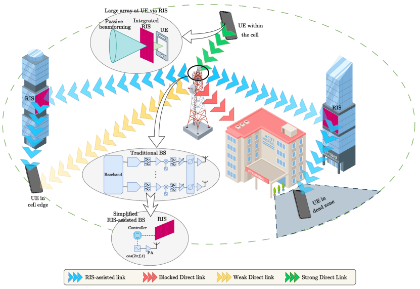
Fig. 1 showcases diverse RIS applications. Among these, a key application is expanding coverage to dead zones, areas beyond the reach of base stations (BSs). This challenge is particularly pronounced in high-frequency communication systems like millimeter-wave (mmWave) and terahertz bands. Traditionally, covering entire environments requires deploying additional BSs or relays, but this can be costly and inefficient. RISs offer a cost/energy-efficient solution as a programmable reflector network within the environment, addressing the coverage dilemma [3]. Another crucial application of RISs involves assisting users located on the cell edges by enhancing their signal reception or mitigating the interference caused by neighboring cells [2]. As the next application, RISs can simplify the hardware design of transceivers by using passive elements instead of active power-hungry components, reducing both power consumption and overall system cost [4]. Ultimately, RISs can realize the implementation of large arrays in user equipment (UE) in a more compact and cost-efficient manner [5].
Based on the RIS deployment location, the RIS applications can be broadly classified into two main groups: BS-side RIS (RIS is deployed in BS proximity) and UE-side RIS (RIS is deployed in UE proximity) systems [6]. This classification stems from considering the large-scale fading issue associated with the transmission over the RIS, where the reflected signal experiences a multiplicative path loss. Therefore, the RIS should be placed near either network terminals (BS or UE) to minimize the overall path loss, which will be discussed in Section II.
Although current literature considers both BS-side and UE-side RIS system designs, it is still unclear how their design parameters change from one to another. In particular, design parameters related to the RIS, such as its size, phase shift adjustment, control link, placement and deployment, and elements type (passive/active), are yet to be differentiated among the two scenarios (BS-side and UE-side). Overlooking these parameters’ differences while designing the RIS-assisted system affects their implementation feasibility, leading to a big gap between theoretical research and industry. For instance, when we examine the control link as an essential design parameter, it becomes apparent that the BS-side RIS system benefits from a more reliable control link. This advantage arises from the static positioning of both the BS and the RIS, enabling the utilization of a robust line-of-sight (LOS) wireless backhaul link or even a fiber optic cable. In contrast, ensuring a similarly robust control link in the UE-side RIS system is challenging, primarily attributed to resource constraints and UE’s mobility. Extending this discussion to the other design parameters can reveal critical issues between the theoretical assumptions and implementation restrictions, which motivates this study.
In this article, we investigate the RIS-related design parameters for the BS-side and UE-side scenarios, shedding light on the critical differences that need to be considered by system designers. Specifically, by considering these parameters individually, we discuss how each scenario has different requirements/settings for that parameter. Accordingly and more comprehensively, we provide a practical guideline that enables researchers and industry experts to clearly distinguish between these two scenarios from the system design and implementation perspectives. Based on the provided discussions, we thoroughly discuss each scenario’s challenges as another key differentiating aspect.
II RIS Placement and Implementation Considerations
The placement of the RIS between the transmitter and receiver within an RIS-assisted communication system plays a key role in determining its overall performance. In this section, we debate the factors affecting the placement of the RIS in the environment and ultimately conclude on the optimal RIS placement that existing literature suggests.
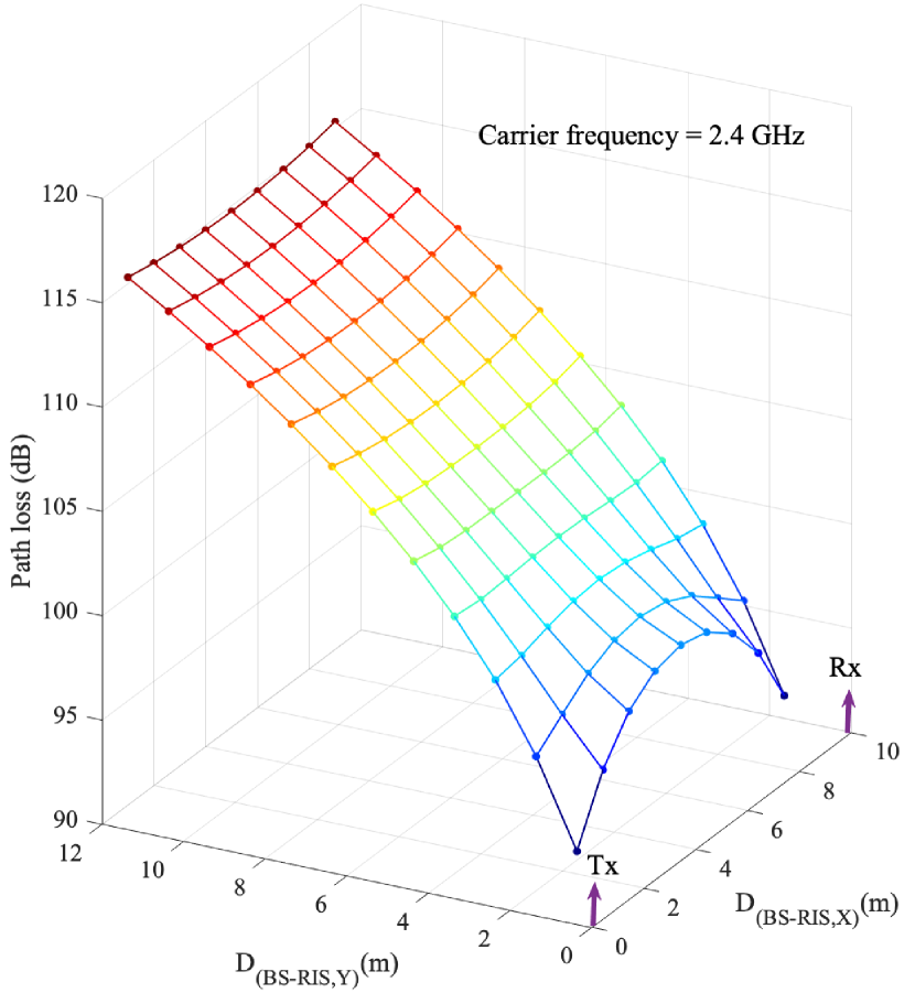
In principle, the potential for RIS placement is virtually limitless, with the possibility of deploying these surfaces across diverse locations within the environment; however, practical limitations narrow down these possibilities. The primary constraint related to deploying RIS lies in the significant path loss associated with the signals imping and reflecting from its surface. Note that, unlike the reflection of light waves from an anomalous mirror, radio frequency (RF) waves’ power decays inversely with the square of the product (not the sum) of the BS-RIS and RIS-UE distances [7]. This observation is further demonstrated in Fig. 2 which illustrates the relationship between RIS location and two-way path loss [7] in an RIS-assisted system, highlighting that positioning the RIS closer to the transceivers effectively reduces the overall BS-RIS-UE path loss. Fig. 2 suggests that integrating the RIS with the transceivers offers optimal placement. Nevertheless, this approach does not consistently yield efficiency, particularly in overcoming signal blockages. Accordingly, it becomes practical to deploy RIS separate from the transceivers. This leads to classifying deployment strategies into two categories: RIS-separated and RIS-integrated. Section VI will further explore these categories.
Note that in Fig. 2, represents the distance between BS and RIS along axis while is the distance between BS and UE. Although this rule is generally correct when we have a full degree of freedom in placing RIS in the environment, some cases necessitate us to consider constant. In such cases, when , the best placing for RIS is , as shown in Fig. 2 and discussed in [8]. However, this is an exceptional case that does not happen frequently.
Another aspect influencing the positioning of the RIS in a particular location is the possibility of establishing a reliable BS-RIS or UE-RIS control link. Theoretically, a control link can be implemented using a wire or wireless medium; nonetheless, due to the path loss issue and wiring feasibility/cost, it is more practical that the closer terminal (BS or UE) is the one that controls the RIS. However, as the BS-RIS/RIS-UE separation increases, both options become less efficient or even impractical. Regarding the first option, the impracticality of using a long wire cable is more evident on the UE side when considering its mobility. Similarly, with a wireless control link, a long-distance channel is associated with more dynamics due to the possible presence of more obstacles and scatterers, decreasing the likelihood of the LOS path and leading to a control link with reduced reliability. In particular, a highly dynamic channel would require to be estimated more frequently, negatively affecting channel acquisition, increasing communication latency, and requiring more time/spectrum resources for its estimation. In contrast, for instance, when the RIS is close to the BS and considering its immobility, its place and orientation can be optimized to guarantee a LOS link. Such a LOS link makes the statistical channel state information (S-CSI) more likely to dominate the instantaneous CSI (I-CSI) for the BS-RIS link. This significantly reduces the channel estimation overhead associated with the BS-RIS link, as the S-CSI is relatively slowly changing (spans multiple channel coherence intervals) compared to the I-CSI. Accordingly, link reliability and latency are positively affected, enhancing overall system performance. This discussion also applies (with less degree) to the UE-RIS control link, where a UE wirelessly controls a nearby RIS. However, notice that considering the mobility of the UE, the availability of the LOS link becomes less certain compared to the BS-RIS case.
Overall, deploying the RIS at either the transmitter or receiver side (with the minimum possible separation distance) is an essential design parameter due to several implementation limitations and constraints. We evaluate BS-side and UE-side RIS deployment strategies in the following two sections.
III BS-Side RIS Deployment
This section presents an overview of the BS-side RIS deployment, including its importance and potential applications.
In practice, the BS maintains a fixed location, allowing for strategic placement/orientation of the RIS to establish a LOS link with the BS. Note that this is unlike the UE-side RIS case, where the mobility of the UE prevents placing the RIS in an optimum location all the time. Furthermore, the proximity and immobility of the BS and the RIS in this design simplify channel estimation and enable a reliable control link from the BS to the RIS, as discussed in Section II. Besides, owing to the more resources and sophisticated hardware available on its side (compared to the UE side), the BS can support advanced functionalities such as cascaded channel estimation/decoupling and joint active and passive beamforming optimization with high-resolution phase shifts to optimally configure the RIS. Additionally, BSs are typically positioned at elevated locations with plentiful space in the surrounding environment, making deploying a large RIS surface possible. A large-size RIS provides significant beamforming/multiplexing/array gain, reducing the overall path loss while maintaining cost-effective and energy-efficient hardware.
To illustrate the potential of BS-side RIS applications, we present two examples highlighting its advantages in alignment with the anticipated 6G requirements in terms of energy saving and spectral efficiency enhancement.
-
1.
Enhanced energy efficiency: In wireless communication systems, RF chains are essential for processing data streams at the transceivers. Since BSs often manage multiple streams simultaneously, a substantial number of RF chains are typically required. Accordingly, implementing innovative methods to reduce the number of RF chains at the BS can be highly advantageous, leading to considerable power savings and enhanced energy efficiency. RISs can be considered among the innovative technologies that deal with this issue. In [4], a BS-side RIS design is proposed to reduce the required number of RF chains at the BS side. This approach involves implementing the RIS to redesign the classical Alamouti’s scheme with a single RF chain instead of the traditional two, reducing cost and power consumption on the transmitter side. Notably, the RIS-assisted Alamouti’s scheme maintains the same diversity order as the original one while substantially improving the bit error rate (BER) performance. The advantage of such an approach in designing the BS is more evident in the generalized scenario of Alamouti’s scheme: a large-scale RIS-assisted space-time block code (STBC) MIMO system.
-
2.
Enhanced spectral efficiency: Enhanced spectral efficiency is crucial in 6G networks because it improves bandwidth utilization efficiency for data transmission across the wireless channel. Employing RIS on the BS side can significantly enhance the system’s spectral efficiency. For instance, integrating passive RISs directly into the BS structure can facilitate passive beamforming/multiplexing cost-effectively [9]. This novel design lets us directly reconfigure the signals incoming/outgoing from the BS without encountering substantial path loss due to the extremely short distance between BS and RIS. Accordingly, the two-way path loss (BS-RIS-UE) is converted to a single-way (BS/RIS-UE), as the RIS is now part of BS. In this regard, the authors demonstrated that deploying an integrated RIS with the BS yields superior performance in terms of spectral efficiency compared to the conventional system without RIS.
IV UE-Side RIS Deployment
Another practical approach for RIS deployment is to place it near a single UE or a cluster of UEs where the BS-RIS distance is significantly larger than the RIS-UE.
Due to UEs’ mobility, they may end up in regions with weak/no network coverage. The conventional solution of adding more BSs/relays to address this issue can be practically costly and energy inefficient [1]. Specifically, this challenge becomes more prominent when higher frequencies (like mmWave and terahertz bands) are adopted in future 6G networks, causing manifold dead zones due to the vulnerability to signal blockages. Since a BS-side RIS may encounter similar obstacles as the BS alone, deploying the RIS on the UE side is a more favorable solution to address the coverage issue. Thus, the RIS can establish an alternative link to the main blocked one by providing reflection paths reaching the dead zone. By strategically positioning each RIS in UE proximity, a reliable LOS link between the RIS and BS/UE can be guaranteed [3]. A relatively more reliable control link (compared to the BS-RIS link) enables the UE to control the RIS independently from the BS.
Here, we present two examples from the current literature to provide concrete context to the concept of UE-side RIS and its impact on the 6G requirements.
-
1.
Enhanced reliability: Future wireless networks can sustain connection reliability by extending the coverage to dead zones and cell edges using RISs at the UE side, providing a reflection link to compensate for the direct weak/blocked link. Generally, as discussed in [10], a primary use-case for RIS is extending the coverage to the cell edge and dead zone when the direct link between the BS and UE is weak or blocked, as illustrated in Fig. 1. Another attractive scenario is the coverage extension in an outdoor-to-indoor (O2I) setup where the BS is implemented outdoors while the UE is located indoors and receives weak/no signals [11].
-
2.
Enhanced user-experienced data rate: Enabling a large-scale antenna array at the UE has been seen as unfeasible due to size, energy consumption, and cost limitations [5]. Nevertheless, the recent study of [5] has introduced a UE-side RIS design that leverages multi-layer RIS surfaces to achieve a system performance similar to that obtained using a large-scale antenna array. Consequently, an amplified beamforming/array gain can be realized, raising the user-experienced data rate.
V RIS Control and Configuration
In order to achieve optimal performance in an RIS-assisted system, a dynamic RIS configuration based on I-CSI is required. Therefore, the responsible terminal (BS or UE) should calculate the optimal phase shift profile and convey this information to the RIS’s control unit through the control link. Inefficient control and configuration can negatively affect the overall performance of the system by limiting the functionality of the RIS. In what follows, we discuss the practical considerations of the control link and phase shift configuration for each BS-side and UE-side scenario.
V-A Control Link
In order to guarantee optimal passive beamforming, a robust control link with sufficient capacity to transmit control information from the responsible terminal to the RIS needs to be established. Based on the operating scenario and RIS deployment strategy, selecting a control link medium can encompass various options, such as fiber-optic cables, metal-based wiring, or wireless links.
For BS-side RIS deployments, where both the BS and RIS have fixed locations, fiber-optic cabling can be the optimal choice for the control link regarding capacity and reliability. Nevertheless, a wireless link can be an alternative option for more flexible RIS placement/orientation to achieve maximum performance.
In contrast, when deploying the RIS on the UE side, the cabling/wiring solution is often impractical due to UE mobility. Establishing a dedicated wireless control link is the most feasible solution in such instances. The only exception is when the RIS is integrated within the UE, as the stationary positions of the UE and RIS relative to each other make metal-based wiring a viable option for creating a dedicated control link [5].
V-B Phase Shift Profile Design
One of the main and essential functions of RISs is their ability to focus the reflected signal into a specific spatial direction without using active RF components (passive beamforming). This is realized by adjusting the phase shifts of individual RIS elements relying on the CSI. However, acquiring perfect I-CSI of a large number of RIS elements has always been considered a bottleneck in RIS-assisted systems. Phase shift adjustment can be continuous or discrete, each with pros and cons. Continuous phase shifting results in superior performance enhancement, while discrete phase shift adjustment is cost-effective and less complex.
In a BS-side RIS scenario, considering the computational/power resources available at the BS, optimizing joint active-passive beamforming is feasible to achieve maximum performance. On the other hand, since the UEs typically suffer from limited computational/power resources, and the UE-RIS control link cannot guarantee high-capacity communication, implementing low-complexity RIS configuration schemes in the UE-side RIS is essential. Heuristic approaches can be exploited to design a low-complex phase-shift configuration scheme [12]. Besides, due to the low-capacity control link, control signaling is preferred to be simple to prevent high signaling overhead and long latency. Another alternative can be adopting codebook-based schemes to decrease computational complexity and power consumption in the UE and signaling overhead between the UE and RIS while maintaining satisfactory performance [13]. Specifically, instead of solving a complex optimization problem, UE can activate a set of reflection patterns (RP) at the RIS one by one and learn the optimal RP for communication [13].
VI Advancing Towards 6G: How RISs Shape the Requirements of 6G Networks
This section highlights different advantages associated with both BS-side and UE-side RIS deployments, with a particular emphasis on meeting the requirements of 6G networks. These requirements include high energy/spectral efficiency, low latency, massive connectivity, ultra-reliability, and high data rates. Specifically, we discuss how each RIS deployment can enhance various 6G requirements.
VI-A Integrated or Separated RIS: Which Serves 6G Requirements Better?
Considering only free-space path loss, when the RIS is implemented closer to the BS/UE, multiplicative path loss decreases (see Fig. 2); therefore, in a BS/UE-side RIS scenario, the optimum placing for an RIS is to integrate into the BS/UE seamlessly. However, in a realistic environment, the optimal placement for RIS is not only a function of distance but also various factors like shadowing, large/small scale fading, space limitation, UE movement, and environmental obstacles that can affect it. Such factors result in optimal RIS placement separated from the BS/UE.
In this regard, two categories of RIS deployments can be introduced: BS/UE-side integrated RIS and BS/UE-side separated RIS. BS/UE-side integrated RIS results in the minimum path loss. Hence, we can maximize data rate and spectral efficiency while minimizing the communication latency. Furthermore, by integrating RIS into each terminal, we can replace active components with passive elements, resulting in enhanced energy efficiency. However, the BS/UE-side integrated design does not have flexibility in RIS placement; hence, it cannot circumvent blockages and provide redundant paths. Therefore, BS/UE-separated design is recommended to increase connection density and network reliability.
In conclusion, in a realistic network, both integrated and separated RIS designs should be adopted concurrently to meet the high standards of 6G networks.
VI-B Towards 6G: The Strategic Role of BS-Side RIS
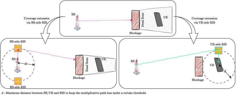
Generally, BSs are placed within an environment to provide broad coverage. When an RIS is deployed near the BS, it inherits this wide coverage capability. This feature allows us to leverage the RIS as a passive beamformer, reducing costs, conserving power, and enhancing energy efficiency at the BS, as fewer active components like RF chains and phase shifters are required. As explained in Section VI-A, by placing RIS separated from the BS, the transmitted signal can circumvent the environmental blockages. However, to circumvent a faraway blockage, we may increase the BS-RIS distance, which increases multiplicative path loss. On the other hand, to keep the multiplicative path loss under a certain threshold, maximum BS-RIS distance should be maintained. In this point of view, BS-side RIS has minor flexibility in enhancing connection density and communication reliability. As illustrated in Fig. 4, maintaining the maximum distance between BS and RIS, even deploying two BS-side RIS cannot cover the whole dead zone.
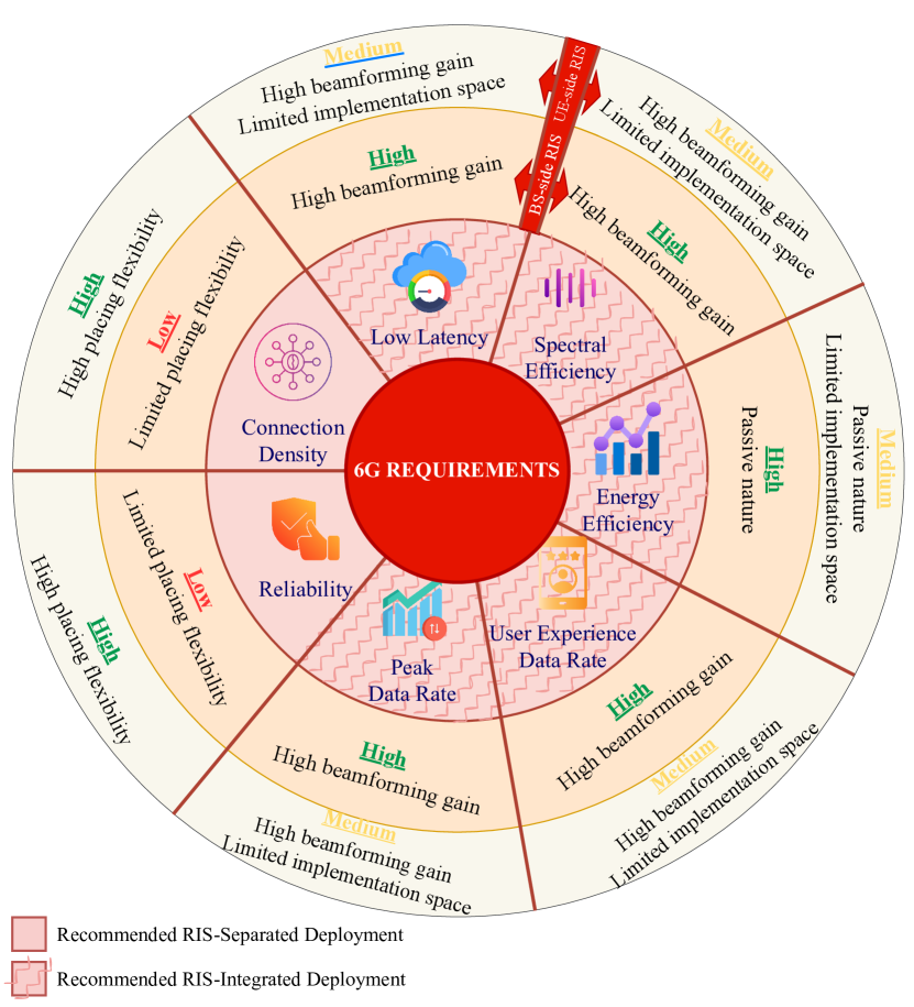
On the other hand, considering the passive nature of RIS elements, an important key point in compensating multiplicative path loss is adopting an RIS with a large number of elements. Fortunately, there is enough space near the BS to accommodate a large RIS. Furthermore, BS is equipped with sophisticated hardware to support complex computational workloads for a large RIS, such as channel estimation and joint active-passive beamforming optimization. A large passive RIS can significantly increase beamforming gain without consuming too much power, enhancing user-experienced/peak data rate and spectral/energy efficiency, and reducing communication latency. Additionally, by adopting a large RIS and jointly optimizing active-passive beamforming gain, we can enrich the channel effectively, positively affecting user-experienced/peak data rate, spectral efficiency, and communication latency. Fig. 3 summarizes the influences of RIS in 6G requirements.
VI-C UE-Side RIS: A Flexible Solution for 6G Network Requirements
Unlike BS, UEs generally do not have fixed positions and can move freely in the environment, potentially ending with dead zones. As explained in the last sub-section, BS-side RIS deployment might not effectively circumvent the blockages due to the limited placing flexibility. Therefore, as depicted in Fig. 4, the RIS can be positioned near the dead zone to circumvent the blockage more effectively while keeping the multiplicative path loss under a certain threshold. In this context, UE-side RIS can enhance connection density and communication reliability by reserving virtual LOS to the dead zone. On the other hand, integrating RIS within the UE realizes a large array at the UE [5], which can considerably enhance beamforming/array gain, directly increasing the user-experienced/peak data rate and spectral efficiency, while reducing communication latency.
However, unlike the BS-side RIS deployment, we may encounter space limitations when implementing a large array on the UE side. For instance, space limitation for RIS implementation is evident in a UE-side integrated RIS deployment. The authors in [5] offered a multi-layer RIS structure to address this dilemma. As another example, in an O2I coverage extension scenario [11], where a transparent RIS is embedded into a window, space constraints may limit the size of the RIS, potentially resulting in insufficient passive array gain to compensate for multiplicative path loss. Mutli-layer RIS design studied in [5] for UE-side integrated RIS can potentially be helpful for such UE-side separated RIS scenarios. Active RIS can be another alternative to address the path loss problem [14]. Accordingly, due to limited implementation space, passive beamforming gain in UE-side RIS designs is expected to be less than the BS-side RIS deployments. Despite this, some exceptions can be found in UE-side RIS designs. For instance, deploying large RIS surfaces on building facades near dead zones is feasible in a scenario like a street canyon. These large surfaces offer significant passive array gain to compensate for path loss. Here, passive RIS deployment is preferred to active deployment, avoiding unnecessary cost and power consumption, resulting in enhanced energy efficiency.
However, deploying large RIS near the UE presents a unique challenge: the overhead associated with cascaded channel estimation and RIS configuration [10]. Given the UE’s limited computational/power resources, these overheads can increase system latency. Accordingly, striking a balance between the RIS size and the signaling overhead while considering efficient channel estimation and RIS configuration strategies (like codebook-based configuration) is of great importance [15]. Adopting novel designs like plug-in RIS [3], which simplifies channel estimation and RIS configuration, can facilitate UE-side RIS deployment with higher energy efficiency and lower latency.
Fig. 3 illustrates different 6G requirements and summarizes the effect of each RIS deployment on these requirements. Generally, RIS positively impacts the 6G requirements; however, practical limitations should be considered for each deployment. For some 6G requirements, BS-side RIS provides higher performance enhancements, while UE-side RIS deployment is better for the other requirements. In a complete network, the hybrid implementation of these two deployments can complement the network needs.
VII Conclusion and Future Horizon
RISs have shown remarkable promise in crafting intelligent radio environments in wireless communications. These environments are tailored to meet the demanding needs of future wireless networks, including ultra-reliable, low-latency communication and widespread connectivity. Exploring practical deployment strategies and understanding their implications is crucial to fully harnessing the benefits of RIS-assisted networks. Our discussion has spotlighted two pivotal RIS applications: one focused on the BS side and the other on the UE side, delving into the practical aspects of managing and configuring RIS technologies. Moreover, we have highlighted how these applications influence the requirements of 6G networks, showcasing their potential to revolutionize future communications.
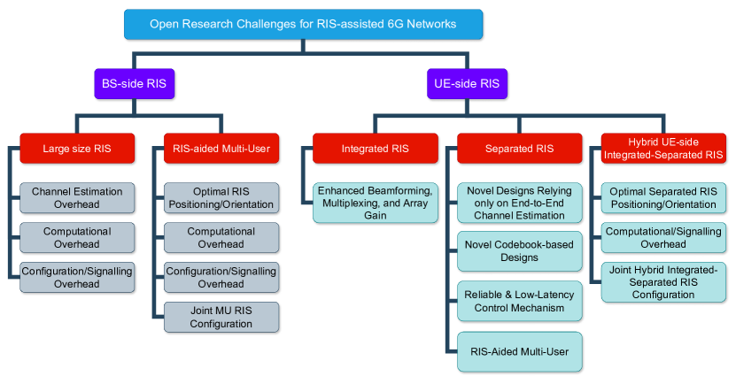
Despite significant progress, RIS technology confronts several practical challenges that must be overcome to achieve cost-effective and efficient integration into next-generation networks. Our article outlines future research directions, underscoring the need for advancements in BS-side RIS, such as developing larger surfaces capable of simultaneously supporting multiple users. This approach, however, introduces complexities, especially in managing the increased overhead caused by integrating numerous RIS elements for joint active-passive beamforming. On the flip side, UE-side RIS poses its own set of challenges. Innovations in beamforming, multiplexing, and array gain are essential, particularly through the integration of RIS into user devices. For deployments where RIS is separate from the UE, the focus shifts to crafting low-complexity signaling methods that account for the limited computational resources of UEs and the criticality of maintaining a stable control link. As we stand on the brink of a new era in wireless communication, it is evident that both integrated and separate UE-side RIS deployments will play a fundamental role. This necessitates exploring hybrid approaches that blend the strengths of both models to navigate the complexities of advanced network ecosystems.
Fig. 5 illustrates the path forward for BS-side and UE-side RIS deployments, marking the key areas where innovation is essential to realize the full potential of RIS in shaping the future of wireless communications.
References
- [1] E. Basar et al., “Wireless communications through reconfigurable intelligent surfaces,” IEEE Access, vol. 7, pp. 116753–116773, Aug. 2019.
- [2] B. Sihlbom, M. I. Poulakis, and M. Di Renzo, “Reconfigurable intelligent surfaces: Performance assessment through a system-level simulator,” IEEE Wireless Commun., vol. 30, no. 4, pp. 98–106, 2023.
- [3] M. Raeisi, I. Yildirim, M. C. Ilter, M. Gerami, and E. Basar, “Plug-in RIS: A novel approach to fully passive reconfigurable intelligent surfaces,” arXiv preprint arXiv:2311.09626, 2023.
- [4] A. Khaleel and E. Basar, “Reconfigurable intelligent surface-empowered MIMO systems,” IEEE Syst. J., vol. 15, pp. 4358–4366, Aug. 2021.
- [5] K. Liu, Z. Zhang, L. Dai, and L. Hanzo, “Compact user-specific reconfigurable intelligent surfaces for uplink transmission,” IEEE Trans. Commun., vol. 70, pp. 680–692, Nov. 2022.
- [6] C. You, B. Zheng, W. Mei, and R. Zhang, “How to deploy intelligent reflecting surfaces in wireless network: BS-Side, User-Side, or both sides?,” J. commun. inf. netw., vol. 7, pp. 1–10, Mar. 2022.
- [7] S. W. Ellingson, “Path loss in reconfigurable intelligent surface-enabled channels,” in IEEE 32nd Annual International Symposium on Personal, Indoor and Mobile Radio Communications (PIMRC), pp. 829–835, 2021.
- [8] Y. Ren et al., “On deployment position of RIS in wireless communication systems: Analysis and experimental results,” IEEE Wireless Commun. Lett., vol. 12, pp. 1756–1760, Jul. 2023.
- [9] Y. Huang, L. Zhu, and R. Zhang, “Integrating intelligent reflecting surface into base station: Architecture, channel model, and passive reflection design,” IEEE Trans. Commun., vol. 71, no. 8, pp. 5005–5020, 2023.
- [10] E. Basar and I. Yildirim, “Reconfigurable intelligent surfaces for future wireless networks: A channel modeling perspective,” IEEE Wireless Commun., vol. 28, pp. 108–114, Apr. 2021.
- [11] X. Xie et al., “Joint precoding for active intelligent transmitting surface empowered outdoor-to-indoor communication in mmWave cellular networks,” IEEE Trans. Wireless Commun., vol. 22, pp. 7072–7086, Feb. 2023.
- [12] H. Zhou, M. Erol-Kantarci, Y. Liu, and H. V. Poor, “A survey on model-based, heuristic, and machine learning optimization approaches in RIS-aided wireless networks,” IEEE Commun. Surveys Tutor., Dec. 2023. Early Access, doi: 10.1109/COMST.2023.3340099.
- [13] J. An et al., “Codebook-based solutions for reconfigurable intelligent surfaces and their open challenges,” IEEE Wireless Commun., pp. 1–8, Nov. 2022.
- [14] Z. Zhang et al., “Active RIS vs. passive RIS: Which will prevail in 6G?,” IEEE Trans. Commun., vol. 71, no. 3, pp. 1707–1725, 2023.
- [15] A. Zappone, M. Di Renzo, F. Shams, X. Qian, and M. Debbah, “Overhead-aware design of reconfigurable intelligent surfaces in smart radio environments,” IEEE Trans. Wireless Commun., vol. 20, no. 1, pp. 126–141, 2021.