Spatial Control of Hybridization-Induced Spin-Wave Transmission Stop Band
Abstract
Spin-wave (SW) propagation close to the hybridization-induced transmission stop band is investigated within a trapezoid-shaped 200 nm thick yttrium iron garnet (YIG) film using time-resolved magneto-optic Kerr effect (TR-MOKE) microscopy and broadband spin wave spectroscopy, supported by micromagnetic simulations. The gradual reduction of the effective field within the structure leads to local variations of the SW dispersion relation and results in a SW hybridization at a fixed position in the trapezoid where the propagation vanishes since the SW group velocity approaches zero. By tuning external field or frequency, spatial control of the spatial stop band position and spin-wave propagation is demonstrated and utilized to gain transmission control over several microstrip lines.
I Introduction
Driven by potential spin-wave-based applications in computing and data processing, the field of magnonics has garnered growing interest in recent years [1, 2, 3, 4, 5, 6, 7, 8, 9, 10, 11]. To perform logic operations encoded within magnon currents various approaches were suggested and realized, such as interference-based logic gates [1, 12, 10, 13] or magnonic crystals that exploit the periodicity-induced formation of bandgaps in the spin-wave spectrum [14, 15, 16, 17, 18, 19, 20, 21]. These devices rely on precise control and manipulation of spin-waves with wave vector k within a material with magnetization M. Recently, a hybridization-induced spin-wave-transmission stop band was demonstrated in 200 nm yttrium iron garnet (YIG) [22], adding to the list of options for engineering spin-wave propagation. It was shown that the hybridization of two different Damon Eshbach-like (DE) () SW modes causes a frequency- and field-dependent suppression of SW propagation in a film with in-plane magnetization. Furthermore, it is well known that at the edges of thin magnetic films, depending on the magnetization direction, the effective field is locally reduced in order to avoid the generation of magnetic surface charges [23, 16, 24]. This allows for shape-modulated local variations of SW propagation. Combining this effect with the transmission stop band may provide enhanced control over spin-wave propagation dynamics and facilitate the implementation of magnonic devices.
In this report, we investigate the effect of the geometry-induced variation of the effective field in a 200 nm YIG film on the hybridization-induced stop band. We demonstrate that the spin-wave propagation distance can be actively controlled within a trapezoid-shaped magnetic film as the reduced effective field locally enforces the hybridization condition. Experimental dispersion measurements and micromagnetic simulations using TetraX [25] are conducted to determine the full film stop band condition. From further micromagnetic simulations using MuMax3 [26], the effective internal field of a trapezoid geometry is determined. An inhomogeneous field distribution with a gradual decrease along the trapezoid’s length is observed. We experimentally investigate the corresponding spin-wave propagation within the trapezoid in a DE-like geometry using time-resolved magneto-optic Kerr effect (TR-MOKE) microscopy [27, 28, 29, 30, 31] and broadband spin-wave spectroscopy. Bending of wavefronts, the formation of edge channels, and a gradual decrease of wavelength along the propagation direction are observed. At a distinct position in the trapezoid, the propagation ceases. We show that this stop position is locally induced by the reduced effective field, which grants access to the spin-wave transmission stop band. Based on these findings, we demonstrate spatial control of spin-wave propagation within a trapezoid-shaped device by tuning the static external field close to the stop band. We utilize this effect for the active transmission control between microstrip lines.
II Experimental Results
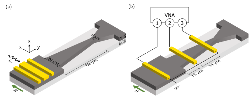
The first set of experiments was carried out using time-resolved magneto-optic Kerr effect (TR-MOKE) microscopy. Here, the dynamic out-of-plane magnetization component is spatially mapped in the -plane, and a direct observation of spin-wave propagation in the sample is obtained. Simultaneously, the reflectivity is detected, providing a topographic map of the sample. The measurements were conducted on a 200 nm thick yttrium iron garnet (YIG) film grown by liquid phase epitaxy on a gadolinium gallium garnet (GGG) substrate. The trapezoid shape, with a gradual continuation back to the full film, was patterned by means of optical lithography and subsequent Argon sputtering of the YIG film. For the excitation of spin-waves, a coplanar waveguide (CPW) was fabricated on top of the YIG film by optical lithography and electron beam evaporation of Ti(5 nm)/Au(210 nm). During the measurements, the external bias field was fixed along the CPW, so spin-waves in a DE-like geometry were excited [32]. A schematic of the measurement geometry can be found in Fig. 1(a).
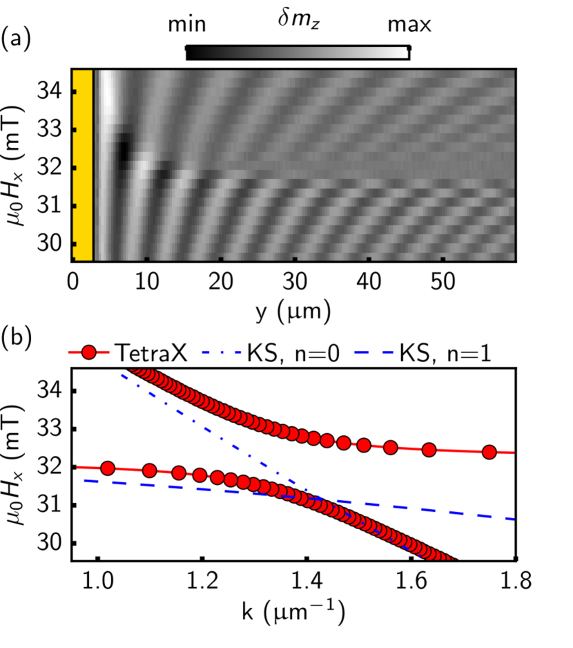
As a preliminary step, the spin-wave stop band in the unpatterned plane YIG film was identified by examining SW propagation far away from the patterned trapezoid structure. In this context, line scans of the Kerr signal along the -direction were recorded as a function of the applied external field at a constant microwave frequency of GHz. The result is depicted in Fig. 2(a). Here, a clear suppression of spin-wave propagation around 32 mT can be observed. Previous work [33, 22] has shown that hybridization between the DE-mode and the first-order perpendicular standing spin-wave (PSSW) mode can create a spin-wave stop band in 200 nm YIG. This is further illustrated in Fig. 2(b) by micromagnetic simulations with TetraX [25], an open-source Python package for finite-element-method micromagnetic modelling [25]. In zeroth-order perturbation theory, according to Kalinikos and Slavin (KS) [34], the n=0 mode (blue dash-dotted line) and n=1 mode (blue dashed line) cross each other. This degeneracy is lifted by the formation of an avoided crossing in the micromagnetic simulations (red line). This leads to a flattening of the dispersion relation and, in turn, to a decrease in group velocity [22]. For the given experimental parameters, the stop band is predicted at approximately 32 mT, consistent with the observed suppression of propagation in the full film line scans. We thus conclude that the pronounced attenuation can be attributed to the hybridization-induced stop band.
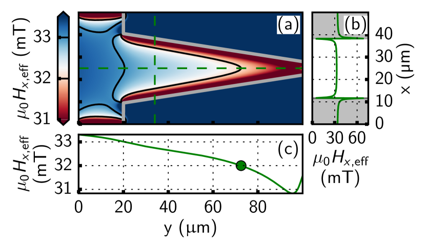
To understand the influence of the trapezoid geometry on SW propagation, and in turn, on the hybridization condition, further micromagnetic simulations were performed [26] to determine the effective field of the tapered SW waveguide. Fig. 3(a) shows the spatial distribution of the -component of the effective field at an externally applied field mT. The simulations revealed that the effective field varies locally inside the trapezoid and is strongly reduced at the YIG edges. The iso-field lines (black lines), which display rounded triangular-like features, further illustrate the inhomogeneous spatial distribution. Along the width of the trapezoid (Fig. 3(b)), we observe sharp edge pockets of low internal field, and a gradual decrease of field along the axis of spin-wave propagation (Fig. 3(c)). The origin of this inhomogeneity of the effective field lies in the geometry-induced demagnetizing field, which aims to avoid the formation of magnetic surface charges [23, 24].
Another important consideration regarding the effect of the modified trapezoid waveguide is the emergence of additional width modes in the SW dispersion relation due to the finite waveguide width [35, 36, 37]. However, this width quantization does not affect the PSSWs, and the intersection of modes is still present. Thus, we argue that the key influence of the trapezoid geometry on the stop band is the reduction in effective field which results in a local variation of the dispersion relation. A more detailed discussion concerning the width quantization can be found in the supplementary material.
Next, we experimentally investigate the effect of the geometry-induced field distribution on spin-wave propagation. Fig. 4(a) displays TR-MOKE measurements in which plane spin-waves are launched from the CPW into the trapezoid in the -direction, with an excitation frequency GHz and a static external field mT. Changes in the propagation characteristics are observed upon entering the trapezoid. Apart from a prominent mode with slightly bent wavefronts in the trapezoid center, a localized mode with strongly bent wavefronts close to the edges appears. We also note that a magnetic contrast right at the edges of the patterned structure was observed in some Kerr images. We argue that this artifact is due to imperfections in the fabrication process and discuss it in more detail in the supplementary material.
The observed bending of wavefronts can be attributed to the inhomogeneous internal field profile [24], where a local reduction in the effective field causes a shift towards lower fields and lower wavelengths in the spin-wave dispersion relation. Additionally, the edge localization of modes is a direct consequence of the low-field pockets in the effective field distribution (Fig. 3(b)) as reported previously [38, 39, 30].
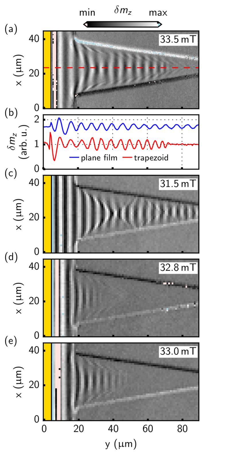
Furthermore, the center mode changes wavelength as it travels through the trapezoid structure. Notably, it comes to a halt at a specific position in space, beyond which the spin-wave propagation is almost entirely suppressed. This behaviour is illustrated in more detail in Fig. 4(b), where a -line profile (red curve) along the red dashed line in Fig. 4(a) is plotted. A line scan on plane YIG (blue curve), far away from any patterned structure, is also presented for comparison. As the spin-wave enters the trapezoid, its wavelength gradually decreases up to more than 50%, consistent with the simulated decrease in the effective field (Fig. 3(c)). However, the propagation abruptly ceases at a specific position in space (m). From Fig. 3(c), we observe that the stop position of the center mode within the wedge corresponds to an estimated effective field of about 32 mT which aligns well with the measured full film hybridization condition (Fig. 2). Thus, we conclude that the reduction in effective field at different positions in space leads to the local dispersion entering the hybridization regime at a specific position in space, resulting in a sharp local attenuation of spin-wave propagation.
Now, we aim to apply our findings towards the active manipulation of spin-wave propagation. To this end, additional Kerr images as a function of the external field were taken and are depicted in Figs. 4(c)-(e). Below the hybridization field, at 31.5 mT (Fig. 4(c)), propagation along the full length of the trapezoid without any sharp attenuation is present. No spatial suppression of propagation is observable since the effective field is only further reduced inside the trapezoid, and thus, the stop band regime is never reached. We also note a complex spatial beating profile with a prominent node at m, and several less prominent ones. This self-focusing effect results from interference of the width modes induced by the tapered waveguide geometry and has been reported in magnonic microstripes before [35, 36]. Furthermore, caustic-like beams induced by the corners where the full film transitions into the trapezoid may emerge [22, 40]. These caustic-like beams are reflected back and forth at the edges, resulting in non-equidistant areas of higher and lower amplitude.
On tuning the external field slightly above 32 mT (Figs. 4(d)-(e)), however, the spin-wave propagation ceases at different positions in space. Furthermore, the boundaries of the spin-wave pattern display a shape reminiscent of the iso-field lines in the effective field. As the external field increases, the positions where the dispersion relation locally gains access to the transmission stop band also shift further outward along the -direction. As a result, the geometry-induced hybridization allows to actively control the spin-wave propagation distance merely by tuning the external field within a reasonable range.
Further all-electrical Vector Network Analyzer (VNA) spin-wave spectroscopy measurements were conducted with the intention to demonstrate the control of spin-wave propagation within a potential magnonic device. For this purpose, three 800 nm wide Au microstrips were patterned at different positions along the trapezoid structure. One microstrip served as a source of spin-wave excitation, while the other two served for detection. The microstrips were connected to separate ports of a four-port VNA, and broadband spin-wave spectroscopy was performed. Note that the choice to employ microstrips instead of CPWs was made in order to obtain a more continuous range of wavenumbers for both the excitation and detection processes. A sketch of the measurement geometry is depicted in Fig. 1(b).
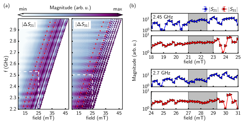
Fig. 5(a) displays the detected spin-wave transmission spectra showcasing the amplitudes of the scattering parameters , in terms of and . We point out that, in the following discussion, denotes the absolute values of the detected scattering parameters whereas refers to absolute values where a high-field subtraction method was applied. Also note that for better visibility, only data close to the stop band condition is depicted. Full transmission spectra, along with more detailed information about the data processing procedure, can be found in the supplementary material. Both spectra exhibit amplitude oscillations with the spectrum displaying shorter spacing between these oscillations. This is due to the change of the lateral spin wave profile, where the positions of high-amplitude and caustic-like nodes shift due to changes in the external magnetic field and applied frequency. This effect leads to a smaller node spacing in the field domain at the location of the third microstrip due to the gradual decrease in trapezoid width [35].
Moreover, distinct wide regions with low to no transmission in the spectra (highlighted by red dotted lines) occur at conditions in accordance with the spin wave stop band. For the transmission , this band is noticeably broader compared to the spectrum and is reached at lower frequencies at a given field (compare white dashed lines). This is a direct consequence of the spatially varying occurrence of the hybridization condition suppressing the propagation of spin waves over a broader range of fields and frequencies the further they advance along the trapezoid. To put it differently, distinct external field and frequency conditions exist where transmission is absent in both and , transmission is observed only in , and transmission occurs in both and . As a result, selective control over the transmission between the microstrips can be achieved by slightly tuning the frequency or the applied bias field.
This is further illustrated in the continuous wave (CW) mode measurements at fixed frequencies shown in Fig. 5(b). The regions of suppressed transmission shift with applied frequency and span over a broader field range in the parameter. The hybridization-induced stop band (highlighted by gray-shaded regions) extends to higher fields due to localized effective field reduction. For instance, at 2.45 GHz and with a field of 23 mT, we observe transmission in the channel but minimal transmission in the trace, similar to 2.7 GHz at 29 mT. Interestingly, the transmission in also appears to be suppressed for fields slightly below the hybridization field. Additional TR-MOKE data in the supplementary material reveals that this behavior can be attributed to the formation of caustic-like beams that are significantly attenuated upon propagation along the geometry.
To conclude this section, we suggest employing multiple microstrips along the trapezoid geometry for potential logic operation. Moreover, in the supplementary material, we provide further discussion on properties of the hybridization, such as its thickness dependence.
III Conclusion
In conclusion, we demonstrated the feasibility of actively controlling the spin-wave propagation distance by combining the hybridization-induced stop band and a geometry-induced variation of the effective field in 200 nm YIG within a trapezoid-shaped magnetic film. Experiments and micromagnetic simulations were performed to gain insight into the effect of the trapezoid geometry on the effective field. The results show that the spin-wave transmission stop band locally induces the stop position, allowing for spatial control of spin-wave propagation within a trapezoid-shaped device by tuning the static external field close to the stop band. Using multiple microstrips along the trapezoid, we further demonstrated the feasibility of active transmission control between microstrips by external field and frequency. The proposed method offers a promising approach for further advancing spin-wave-based computing and data processing applications.
References
- [1] K.-S. Lee and S.-K. Kim, “Conceptual design of spin wave logic gates based on a mach–zehnder-type spin wave interferometer for universal logic functions,” J. Appl. Phys., vol. 104, p. 053909, Sept. 2008.
- [2] T. Schneider, A. A. Serga, B. Leven, B. Hillebrands, R. L. Stamps, and M. P. Kostylev, “Realization of spin-wave logic gates,” Appl. Phys. Lett., vol. 92, p. 022505, Jan. 2008.
- [3] V. V. Kruglyak, S. O. Demokritov, and D. Grundler, “Magnonics,” J. Phys. D: Appl. Phys., vol. 43, p. 260301, July 2010.
- [4] A. Khitun and K. L. Wang, “Non-volatile magnonic logic circuits engineering,” J. Appl. Phys., vol. 110, p. 034306, Aug. 2011.
- [5] A. V. Sadovnikov, C. S. Davies, S. V. Grishin, V. V. Kruglyak, D. V. Romanenko, Y. P. Sharaevskii, and S. A. Nikitov, “Magnonic beam splitter: The building block of parallel magnonic circuitry,” Appl. Phys. Lett., vol. 106, p. 192406, May 2015.
- [6] A. V. Chumak, V. I. Vasyuchka, A. A. Serga, and B. Hillebrands, “Magnon spintronics,” Nat. Phys., vol. 11, pp. 453–461, June 2015.
- [7] Q. Wang, P. Pirro, R. Verba, A. Slavin, B. Hillebrands, and A. V. Chumak, “Reconfigurable nanoscale spin-wave directional coupler,” Sci. Adv., vol. 4, Jan. 2018.
- [8] Q. Wang, A. Hamadeh, R. Verba, V. Lomakin, M. Mohseni, B. Hillebrands, A. V. Chumak, and P. Pirro, “A nonlinear magnonic nano-ring resonator,” npj Comput. Mater., vol. 6, Dec. 2020.
- [9] A. Barman, G. Gubbiotti, S. Ladak, A. O. Adeyeye, M. Krawczyk, J. Gräfe, C. Adelmann, S. Cotofana, A. Naeemi, V. I. Vasyuchka, B. Hillebrands, S. A. Nikitov, H. Yu, D. Grundler, A. V. Sadovnikov, A. A. Grachev, S. E. Sheshukova, J.-Y. Duquesne, M. Marangolo, G. Csaba, W. Porod, V. E. Demidov, S. Urazhdin, S. O. Demokritov, E. Albisetti, D. Petti, R. Bertacco, H. Schultheiss, V. V. Kruglyak, V. D. Poimanov, S. Sahoo, J. Sinha, H. Yang, M. Münzenberg, T. Moriyama, S. Mizukami, P. Landeros, R. A. Gallardo, G. Carlotti, J.-V. Kim, R. L. Stamps, R. E. Camley, B. Rana, Y. Otani, W. Yu, T. Yu, G. E. W. Bauer, C. Back, G. S. Uhrig, O. V. Dobrovolskiy, B. Budinska, H. Qin, S. van Dijken, A. V. Chumak, A. Khitun, D. E. Nikonov, I. A. Young, B. W. Zingsem, and M. Winklhofer, “The 2021 magnonics roadmap,” J. Phys.: Condens. Matter, vol. 33, p. 413001, Aug. 2021.
- [10] Á. Papp, W. Porod, and G. Csaba, “Nanoscale neural network using non-linear spin-wave interference,” Nat Commun, vol. 12, Nov. 2021.
- [11] A. V. Chumak, P. Kabos, M. Wu, C. Abert, C. Adelmann, A. O. Adeyeye, J. Akerman, F. G. Aliev, A. Anane, A. Awad, C. H. Back, A. Barman, G. E. W. Bauer, M. Becherer, E. N. Beginin, V. A. S. V. Bittencourt, Y. M. Blanter, P. Bortolotti, I. Boventer, D. A. Bozhko, S. A. Bunyaev, J. J. Carmiggelt, R. R. Cheenikundil, F. Ciubotaru, S. Cotofana, G. Csaba, O. V. Dobrovolskiy, C. Dubs, M. Elyasi, K. G. Fripp, H. Fulara, I. A. Golovchanskiy, C. Gonzalez-Ballestero, P. Graczyk, D. Grundler, P. Gruszecki, G. Gubbiotti, K. Guslienko, A. Haldar, S. Hamdioui, R. Hertel, B. Hillebrands, T. Hioki, A. Houshang, C.-M. Hu, H. Huebl, M. Huth, E. Iacocca, M. B. Jungfleisch, G. N. Kakazei, A. Khitun, R. Khymyn, T. Kikkawa, M. Klaui, O. Klein, J. W. Klos, S. Knauer, S. Koraltan, M. Kostylev, M. Krawczyk, I. N. Krivorotov, V. V. Kruglyak, D. Lachance-Quirion, S. Ladak, R. Lebrun, Y. Li, M. Lindner, R. Macedo, S. Mayr, G. A. Melkov, S. Mieszczak, Y. Nakamura, H. T. Nembach, A. A. Nikitin, S. A. Nikitov, V. Novosad, J. A. Otalora, Y. Otani, A. Papp, B. Pigeau, P. Pirro, W. Porod, F. Porrati, H. Qin, B. Rana, T. Reimann, F. Riente, O. Romero-Isart, A. Ross, A. V. Sadovnikov, A. R. Safin, E. Saitoh, G. Schmidt, H. Schultheiss, K. Schultheiss, A. A. Serga, S. Sharma, J. M. Shaw, D. Suess, O. Surzhenko, K. Szulc, T. Taniguchi, M. Urbanek, K. Usami, A. B. Ustinov, T. van der Sar, S. van Dijken, V. I. Vasyuchka, R. Verba, S. V. Kusminskiy, Q. Wang, M. Weides, M. Weiler, S. Wintz, S. P. Wolski, and X. Zhang, “Advances in magnetics roadmap on spin-wave computing,” IEEE Trans. Magn., vol. 58, pp. 1–72, June 2022.
- [12] T. Goto, T. Yoshimoto, B. Iwamoto, K. Shimada, C. A. Ross, K. Sekiguchi, A. B. Granovsky, Y. Nakamura, H. Uchida, and M. Inoue, “Three port logic gate using forward volume spin wave interference in a thin yttrium iron garnet film,” Sci. Rep., vol. 9, Nov. 2019.
- [13] H. Qin, R. B. Holländer, L. Flajšman, F. Hermann, R. Dreyer, G. Woltersdorf, and S. van Dijken, “Nanoscale magnonic fabry-pérot resonator for low-loss spin-wave manipulation,” Nat Commun, vol. 12, Apr. 2021.
- [14] G. Gubbiotti, S. Tacchi, M. Madami, G. Carlotti, A. O. Adeyeye, and M. Kostylev, “Brillouin light scattering studies of planar metallic magnonic crystals,” J. Phys. D: Appl. Phys., vol. 43, p. 264003, June 2010.
- [15] A. A. Serga, A. V. Chumak, and B. Hillebrands, “YIG magnonics,” J. Phys. D: Appl. Phys., vol. 43, p. 264002, June 2010.
- [16] B. Lenk, H. Ulrichs, F. Garbs, and M. Münzenberg, “The building blocks of magnonics,” Phys. Rep., vol. 507, pp. 107–136, Oct. 2011.
- [17] Z. K. Wang, V. L. Zhang, H. S. Lim, S. C. Ng, M. H. Kuok, S. Jain, and A. O. Adeyeye, “Nanostructured magnonic crystals with size-tunable bandgaps,” ACS Nano, vol. 4, pp. 643–648, Jan. 2010.
- [18] M. Krawczyk and D. Grundler, “Review and prospects of magnonic crystals and devices with reprogrammable band structure,” J. Phys.: Condens. Matter, vol. 26, p. 123202, Mar. 2014.
- [19] M. A. Morozova, S. V. Grishin, A. V. Sadovnikov, D. V. Romanenko, Y. P. Sharaevskii, and S. A. Nikitov, “Band gap control in a line-defect magnonic crystal waveguide,” Appl. Phys. Lett., vol. 107, p. 242402, Dec. 2015.
- [20] A. J. E. Kreil, H. Y. Musiienko-Shmarova, S. Eggert, A. A. Serga, B. Hillebrands, D. A. Bozhko, A. Pomyalov, and V. S. L'vov, “Tunable space-time crystal in room-temperature magnetodielectrics,” Phys. Rev. B, vol. 100, July 2019.
- [21] F. Lisiecki, J. Rychły, P. Kuświk, H. Głowiński, J. W. Kłos, F. Groß, I. Bykova, M. Weigand, M. Zelent, E. J. Goering, G. Schütz, G. Gubbiotti, M. Krawczyk, F. Stobiecki, J. Dubowik, and J. Gräfe, “Reprogrammability and scalability of magnonic fibonacci quasicrystals,” Phys. Rev. Applied, vol. 11, May 2019.
- [22] C. Riedel, T. Taniguchi, L. Körber, A. Kákay, and C. H. Back, “Hybridization-induced spin-wave transmission stop band within a 1d diffraction grating,” Advanced Physics Research, vol. 2, Feb. 2023.
- [23] J. M. D. Coey, Magnetism and Magnetic Materials. Cambridge University Press, Jan. 2001.
- [24] P. Gruszecki, J. Romero-Vivas, Y. S. Dadoenkova, N. N. Dadoenkova, I. L. Lyubchanskii, and M. Krawczyk, “Goos-hänchen effect and bending of spin wave beams in thin magnetic films,” Appl. Phys. Lett., vol. 105, p. 242406, Dec. 2014.
- [25] L. Körber, A. Hempel, A. Otto, R. A. Gallardo, Y. Henry, J. Lindner, and A. Kákay, “Finite-element dynamic-matrix approach for propagating spin waves: Extension to mono- and multi-layers of arbitrary spacing and thickness,” AIP Adv., vol. 12, p. 115206, Nov. 2022.
- [26] A. Vansteenkiste, J. Leliaert, M. Dvornik, M. Helsen, F. Garcia-Sanchez, and B. V. Waeyenberge, “The design and verification of MuMax3,” AIP Adv., vol. 4, p. 107133, Oct. 2014.
- [27] K. Perzlmaier, G. Woltersdorf, and C. H. Back, “Observation of the propagation and interference of spin waves in ferromagnetic thin films,” Phys. Rev. B, vol. 77, Feb. 2008.
- [28] M. Farle, T. Silva, and G. Woltersdorf, “Spin dynamics in the time and frequency domain,” in Springer Tracts in Modern Physics, pp. 37–83, Springer Berlin Heidelberg, Sept. 2012.
- [29] Y. Au, T. Davison, E. Ahmad, P. S. Keatley, R. J. Hicken, and V. V. Kruglyak, “Excitation of propagating spin waves with global uniform microwave fields,” Appl. Phys. Lett., vol. 98, p. 122506, Mar. 2011.
- [30] H. G. Bauer, J.-Y. Chauleau, G. Woltersdorf, and C. H. Back, “Coupling of spinwave modes in wire structures,” Appl. Phys. Lett., vol. 104, p. 102404, Mar. 2014.
- [31] J. Stigloher, T. Taniguchi, H. Körner, M. Decker, T. Moriyama, T. Ono, and C. Back, “Observation of a goos-hänchen-like phase shift for magnetostatic spin waves,” Phys. Rev. Lett., vol. 121, Sept. 2018.
- [32] R. Damon and J. Eshbach, “Magnetostatic modes of a ferromagnet slab,” J. Phys. Chem. Solids, vol. 19, pp. 308–320, May 1961.
- [33] M. Vaňatka, K. Szulc, O. Wojewoda, C. Dubs, A. V. Chumak, M. Krawczyk, O. V. Dobrovolskiy, J. W. Kłos, and M. Urbánek, “Spin-wave dispersion measurement by variable-gap propagating spin-wave spectroscopy,” Phys. Rev. Applied, vol. 16, Nov. 2021.
- [34] B. A. Kalinikos and A. N. Slavin, “Theory of dipole-exchange spin wave spectrum for ferromagnetic films with mixed exchange boundary conditions,” J. Phys. C: Solid State Phys., vol. 19, pp. 7013–7033, Dec. 1986.
- [35] V. E. Demidov, S. O. Demokritov, K. Rott, P. Krzysteczko, and G. Reiss, “Mode interference and periodic self-focusing of spin waves in permalloy microstripes,” Physical Review B, vol. 77, Feb. 2008.
- [36] X. Xing, Y. Yu, S. Li, and X. Huang, “How do spin waves pass through a bend?,” Scientific Reports, vol. 3, Oct. 2013.
- [37] A. V. Chumak, “Fundamentals of magnon-based computing,” 2019.
- [38] J. Topp, J. Podbielski, D. Heitmann, and D. Grundler, “Internal spin-wave confinement in magnetic nanowires due to zig-zag shaped magnetization,” Phys. Rev. B, vol. 78, July 2008.
- [39] J. Jorzick, S. O. Demokritov, B. Hillebrands, M. Bailleul, C. Fermon, K. Y. Guslienko, A. N. Slavin, D. V. Berkov, and N. L. Gorn, “Spin wave wells in nonellipsoidal micrometer size magnetic elements,” Phys. Rev. Lett., vol. 88, Jan. 2002.
- [40] A. Wartelle, F. Vilsmeier, T. Taniguchi, and C. H. Back, “Caustic spin wave beams in soft thin films: Properties and classification,” Phys. Rev. B, vol. 107, Apr. 2023.