Dynamics of bacterial aggregates in microflows
Abstract. Biofilms are bacterial aggregates that grow on moist surfaces. Thin homogeneous biofilms naturally formed on the walls of conducts may serve as biosensors, providing information on the status of microsystems (MEMS) without disrupting them. However, uncontrolled biofilm growth may largely disturb the environment they develop in, increasing the drag and clogging the tubes. To ensure controlled biofilm expansion we need to understand the effect of external variables on their structure. We formulate a hybrid model for the computational study of biofilms growing in laminar microflows. Biomass evolves according to stochastic rules for adhesion, erosion and motion, informed by numerical approximations of the flow fields at each stage. The model is tested studying the formation of streamers in three dimensional corner flows, gaining some insight on the effect of external variables on their structure.
1 Introduction
As the size of the components of technological devices diminishes, new procedures to measure their inner variables without disturbing the system must be developed. For some microdevices, cheap and environmentally friendly monitoring might be achieved exploiting the bacteria that live in them. Bioremediation policies already benefit from microorganisms. Bacteria feeding on a wide variety of toxic pollutants are deliberately released to clean up oil spills or to purify underground water in farming land and mines [14]. For technological purposes, the ability of bacteria to emit optic signals is more appealing. Microorganisms naturally occurring in the environment fluoresce in response to the presence of certain chemicals or certain processes. Such is the case of bioluminiscence phenomena in the southern seas.
Many bacterial species survive in moist environments forming aggregates called biofilms. Microorganisms adhere to surfaces, forming colonies and changing their phenotype to produce extracellular polymeric matrix (EPS). This matrix shelters them from antibiotics, disinfectants, flows and external aggressions. Biofilms may be considered biological materials, whose properties are governed by environmental factors affecting cellular behavior. Recent attempts to engineer devices out of biofilms successfully produced electrooptical devices [2]. The advancement of synthetic biology is paving the way for the use of biofilms as bioindicators or biosensors in the environment [11]. There are efforts to use biofilms emitting optic signals as microsensors in microdevices. Bacteria can be genetically engineered to change their color in response to variations in the environment. Properly modified, bacteria growing in the devices could give local information of the temperature or other variables, without perturbing the internal flow, since the typical size of bacteria is of the order of microns. To indicate the magnitude of variables on the surfaces they attach to, biofilms should be homogeneous and thin. Pattern formation may largely disrupt the environment they grow in. To be able to exploit bacteria in a controlled way, we must understand the influence of external factors on their collective dynamics.
Biofilms are a mixture of living cells embedded in an exopolyscacharid matrix which contains different kinds of metabolic by-products, that can be generically considered as ’biomass’. In fact, the formation of biofilms in flows may be included in a more general group of physical processes where adhesion mechanisms drive agglomeration of matter to create different geometries. The mechanical behavior of the biomass (EPS, cells, debris) and its interaction with the flow seem to be relevant, allowing for growth of structures that do not align with the streamlines of the flow, but may cross the mainstream or wrap around tubes forming helices instead [13, 12].
In this paper, we propose a computational framework to study the growth of biological aggregates in flows triggered by adhesion of particles, much faster than growth due to nutrient consumption. The biofilm is considered a biomaterial with known average cohesive properties formed by a soft sticky matrix of EPS, debris, and other substances secreted by the cells included in it or floating around. We formulate stochastic rules for biomass adhesion, erosion and motion informed by the continuous flow fields around the expanding aggregate, that are approximated by a finite difference discretization strategy using a fixed mesh to reduce the computational cost. The resulting model is tested studying biofilm streamer formation in laminar corner flows.
The paper is organized as follows. In section 2, we describe the general framework and collect the rules for biomass behavior. Section 3 illustrates the numerical results and discusses the insight gained on the dynamics of the aggregates.
2 Hybrid description of biofilms in microflows
Hybrid models combine continuous descriptions of some relevant fields, such as concentrations, flow fields or EPS matrix production, with discrete descriptions of the cells [1, 7, 6]. The situation we examine here fits better as interaction of the surrounding fluid with a elastic biofilm structure whose growth is mediated by adhesion processes. From a computational point of view, biomass is considered as a mixture of bacteria and organic matter allocated on a grid which may behave in different ways in response to external conditions with a certain probability.
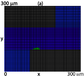
Let us denote by the region occupied by fluid and by the region occupied by biofilm. The whole computational region is divided in a grid of tiles. Each tile may be filled with either substratum, fluid, or biomass, as illustrated in Fig. 1. Since we have in mind applications to microflows, we choose the size of each tile to be of the order of the average size of one bacterium, about - .
The fluid surrounding the biofilm is governed by the incompressible Navier-Stokes equations:
| (1) | |||||
where is the velocity and the pressure. and stand for the density and viscosity of the fluid. The non-slip condition on the velocity holds at the biofilm/fluid interface . A low cost prediction of the evolution of the velocity and pressure fields is provided by second order slight artificial compressibility schemes [3]. Approximated velocities and pressures can be improved using second order implicit gauge schemes [5], if necessary, at a higher cost.
Flow effects are felt by a biofilm on much shorter time scales (seconds) than growth effects (hours) [4]. Biomass attaches, detaches and moves according to the flow fields at each location. Floating bacteria are carried by the fluid. The flow geometry selects preferential adhesion sites on the walls where biofilm seeds may be nucleated [13]. Biofilm nucleation may be successful or not depending on the surface nature and the bacterial strain. The flow also determines the strength of the biofilm [10, 15]. Once a biofilm seed is formed, biomass accumulation is a balance between biomass increase due to adhesion or cellular processes, and loss of bacteria due to erosion [16]. We describe below basic stochastic rules for adhesion, erosion and motion processes, having in mind the model case of bacterial streamers in laminar corner microflows, that will serve as a test later. We focus on fast processes. Growth due to nutrient consumption is neglected here.
Two main adhesion processes are taken into account:
-
•
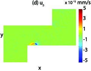
Adhesion of floating cells to walls. In laminar regimes, nucleation of biofilm seeds on the walls is often driven by the geometry. Corners or narrowings may produce secondary flows that drive cells and particles to the walls. Continuous adhesion of bacteria at preferential adhesion sites is taken care of by attaching cells at each step. They distribute on the seed, inside a limited region where the secondary flow is expected to be relevant.
-
•
Once a biofilm seed sticks out from the wall, bacteria and particles swimming with the flow may hit it, and stick to it at a certain rate. Additional biomass blocks are distributed between the tiles located at the biofilm/fluid interface.
and depend on the density of biomass floating in the fluid. is affected by the likeliness of the specific bacterial strain selected to adhere to the walls.
Biomass tiles located on the surface of the biofilm detach due to shear forces exerted by the flow [16]. A probability for biomass detachment is proposed in [9]:
| (2) |
is a measure of the biofilm cohesion. We assume it to be known and constant. measures the shear force felt by cell . Here, we use the magnitude of the shear force due to the flow at the cell location , modified by a geometrical factor that accounts for the local sheltering role of neighboring cells, see [7]. In our numerical experiments, is usually set equal to the shear rate at location multiplied by the fluid viscosity . The shear rate is defined as the spatial rate of change in the fluid velocity field [8]. As for the geometrical factor, it varies according to the main component of the flow, see [7]. In practice, we check erosion in the three directions. At each step and for each biomass tile on the biofilm boundary, we detach biomass with probability . Erosion due to the flow may occur as detachment of single blocks or of whole clusters of biomass with a thinning connection to the rest of the biofilm.
Shear forces exerted by the flow on the biofilm surface detach biomass. Normal forces on biofilm surfaces may move them. The motion of a biofilm block may be seen as the result of the collective motion of small fragments of the aggregate.
The probability for biomass motion in the directions is defined as:
| (3) |
Similar expressions are used in the and directions. is again a measure of the biofilm cohesion. is the force exerted by the flow in the direction (on cell walls normal to the direction) weighted with a geometrical factor accounting for neighbor protection similar to the one used in (2), [7]. and are its counterparts in the and direction. The forces are calculated using the values of the fluid stress tensor at the cell location: for the chosen normal vector .
At each step and for each occupied tile on the biofilm boundary, the biomass moves in the direction with probability pushing its neighbors in that direction too. Motion is in the positive or negative sense depending on the sign of . Similar rules are applied in the and directions.
3 Numerical results
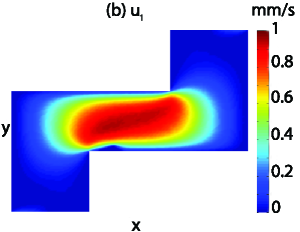
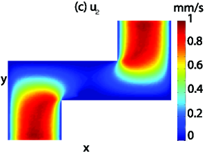
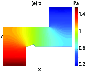
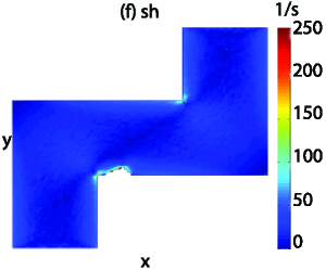
We will fix as a model case of study the growth of streamers in corner microflows, that is well documented experimentally [13]. The computational region is described in Fig. 1(a). A pressure driven flow circulates through the ducts with maximum velocities of about . The structure of the flow is represented in Figs. 1(b)-(f). The density of the liquid is and its viscosity . The bacterial size, and the tile size thereof, is taken to be . The dimensions of the central straight fragment are . Streamers grow mostly in the region between corners. In real experiments, usual values for and are , and . In the numerical tests selected here, we have divided those sizes by to reduce the computational cost.
An initial biofilm seed is placed on the left corner at the bottom, see Figure 1(a). According to [13], the presence of secondary vortices in that area favors adhesion of particles to the wall, becoming a preferential adhesion site. Biomass will be attached to that seed, eroded and moved according to stochastic rules described above.
(a) (b)
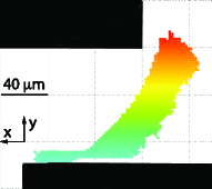
Numerical tests of biofilm growth are performed using this geometry, see Fig. 2. is a measure of the biofilm cohesion estimated from the biofilm Young modulus. Reference [13] gives values in the range . To reduce the computational cost, we adjust it so that our biofilms involve a small number of tiles. Images in Reference [13] yield estimates for the adhesion time of block of biomass per second. Each step of the adhesion-erosion-motion process occurs in a time scale .
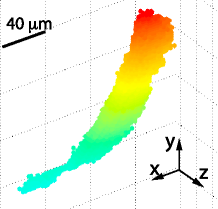
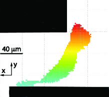
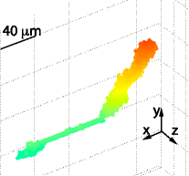
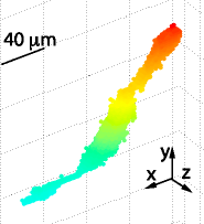
Provided enough biomass attaches to the seed (to avoid streamer detachment) and to the biofilm body (to resist increasing erosion while crossing the current), the aggregate grows into the current, elongates with it, bends when it reaches the curve, approaches the opposite corner, and eventually merges with the additional biofilm seed that should be growing there. The observed effective growth rate is the balance between the biomass that attaches and detaches at each step, and varies during the spread process. It is usually larger before the thread tries to cross the main stream and decreases as it tries to reach the opposite corner while changing its shape.
The aggregate grows into the region of minimum shear rate, that joins the two corners. Once formed, pressure variations move the filament downstream, curving it in a similar way to the experimentally observed threads, and leaving a thin joint with the seed. It reaches the opposite corner from behind, as observed in experimental photographs.
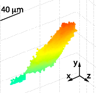
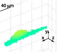
The number of biomass blocks to be attached depends on the selected biofilm cohesion. Too large values of produce expanding balls. Too small adhesion rates to the biofilm produce an elongated thread close to the wall, that eventually feels the corner flow and starts to gain biomass on the top, but may not receive enough biomass to resist the increased erosion and detaches, see Figures 3 (a) and (b). For small values of the connection between the streamer and the seed breaks off, see Figure 3 (c). Too large adhesion rates to the seed favor expansion parallel to the bottom substratum. If is not large enough for the selected cohesion, the biofilm reaches the rightmost wall as shown in Figure 4 (a). Increasing , the biofilm may cross to the opposite corner sustained by a wider basis. If the initial adhesion rates are large enough for the considered cohesion, a sort of fan expands into the main stream. The fan becomes narrower as we reduce the adhesion rates.
Depending on the ratio for the selected , we see narrower or wider streamers. If we increase the cohesion parameter , we must reduce the computational adhesion rates and to see similar behaviors. The failed streamer in Figure 4 (a) reaches successfully the opposite corner sustained by a wider basis when we slightly increase in Figure 4 (b), (c). If the biofilm cohesion is too small, the biofilm seed is eroded and eventually washed out. No thread is formed.
These tests provide insight on the way these structures are formed. Threads experimentally observed [13], however, look more like thin jets and may require a different description. Streamers joining opposite corners appear to be attractor shapes that may be formed under different dynamics.
(a) (b) (c)
(a) (b) (c)

Acknowledgement. D. R. Espeso and A. Carpio were supported by the Autonomous Region of Madrid and the spanish MICINN through grants S2009/ ENE-1597, and FIS2011-28838-C02-02. B. Einarsson was supported by a grant of the NILS program and project FIS2008-04921-C02-01.
References
- [1] Alpkvist, E., Picioreanu, C., Loosdrecht, M.C.M., Heyden, A.: Three-dimensional biofilm model with individual cells and continuum eps matrix. Biotechnol. Bioeng. 94, 961-979 (2006)
- [2] Castellon, E., Chavarria, M., de Lorenzo, V., Zayat, M., Levy, D.: An electro-optical device from a biofilm structure created by bacterial activity. Adv. Mater. 22, 4846-4850 (2010)
- [3] Chorin, A.J.: A numerical method for solving incompressible viscous flow problems. J. Comp. Phys. 2, 12-26 (1967)
- [4] Drescher, K., Shen, Y., Bassler, B.L., Stone, H.A.: Biofilm streamers cause catastrophic disruption of flow with consequences for environmental and medical systems. Proc. Nat. Acad. Sc. 110, 4345-4350 (2013)
- [5] E, W., Lui, J.G.: Gauge method for viscous incompressible flows. Comm. Math. Sci. 1, 317-332 (2003)
- [6] Eberhard, J.P., Efendiev, Y., Ewing, E., Cunningham, A.: Coupled cellular models for biofilm growth and hydrodynamic flow in a pipe. Int. J. Mult. Comp. Eng. 3, 499-516 (2005)
- [7] Rodriguez, D., Einarsson, B., Carpio, A.: Biofilm growth on rugose surfaces. Phys. Rev. E 86, 061914 (2012)
- [8] Finlayson, B.A.: Introduction to Chemical Engineering Computing. Wiley, New Jersey (2012)
- [9] Hermanovic, S.W.: A simple 2d biofilm model yields a variety of morphological features. Math. Biosciences 169, 1-14 (2001)
- [10] Lecuyer, S., Rusconi, R., Shen, Y., Forsyth, A., Vlamakis, H., Kolter, R., Stone, H.A.: Shear stress increases the residence time of adhesion of pseudomonas aeruginosa. Biophys. J. 100, 341-350 (2011)
- [11] Morina, S., Pesceb, S., Tlilib, A., Costea, M., Montuelle, B.: Recovery potential of periphytic communities in a river impacted by a vineyard watershed. Ecol. Indic. 10, 419-426 (2010)
- [12] Rodriguez Espeso, D.: Modeling and simulation of bacterial biofilms. Ph.D. thesis, Universidad Carlos III de Madrid (2013)
- [13] Rusconi, R., Lecuyer, S., Autrusson, N., Guglielmini, L., Stone, H.A.: Secondary flow as a mechanism for the formation of biofilm streamers. Biophys. J. 100, 1392-1399 (2011)
- [14] Schachter, B.: Slimy business-the biotechnology of biofilms. Nat. Biotechnol. 21, 361-365 (2003)
- [15] . Stoodley, P., Cargo, R., Rupp, C.J., Wilson, S., Klapper, I.: Biofilm material properties as related to shear-induced deformation and detachment phenomena. J. Ind. Microb. Biotech. 29, 361-367 (2002)
- [16] Stoodley, P., Dodds, I., Boyle, J.D., Lappin-Scott, H.M.: Influence of hydrodynamics and nutrients on biofilm structure. J. Appl. Microb. Symposium. Supplement 85, 19S-28S (1999)