Electrified Fracture of Nanotube Films
Abstract
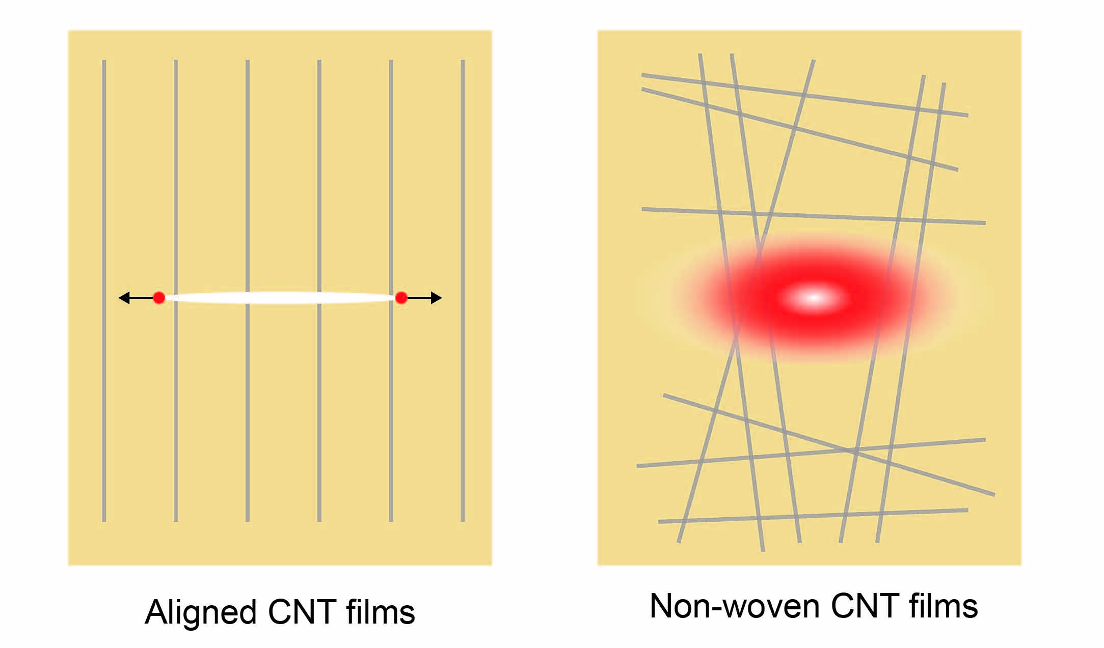
Strong and conductive carbon nanotube films are ideal candidates for lightning-strike protection. Understanding their failure mechanisms by considering the anisotropic and single-fiber nature is essential to improve performance. Our experimental studies show that the single-layer, nanometer-thick films fail under electrification by crack nucleation and propagation, reminiscent of brittle and ductile fracture of materials under mechanical loads. Sharp and diffuse patterns of fracture are identified in aligned and non-woven films, respectively, signaling the strong effect of material anisotropy that is absent in common engineering materials. The fracture is driven by local Joule heating concentrated at the crack fronts instead of force-induced breakage, which is validated by experimental characterization and simulation results at both continuum and atomistic levels.
Lightning striking is an instantaneous but energy-intensive process. The current rises to 200 kA within tens of µs [1, 2], resulting in concentrated damage to materials [3, 1, 4]. Carbon nanotubes (CNTs) are one-dimensional (1D) nanostructures that are mechanically strong and conductive for both heat and charge carriers [5]. CNT fibers, films, and composites have thus been explored for their potential in high-end material applications for lightning-strike protection [6, 7, 8]. However, unlike conventional protection materials in use (e.g., copper, aluminum), the performance of CNT-derived materials highly relies on their microstructures, such as the orientation and packing density of CNTs, since the van der Waals contact between CNTs is much weaker than the sp2 bonding network within the graphitic walls. Recent studies showed improved mechanical and conductive properties of aligned CNT films manufactured from vertically-grown arrays compared to their randomly aligned counterparts, as well as promising performance against lightning strikes [9, 10]. However, the failure mechanism remains unclear due to both the multiphysical nature of the underlying process and the multiscale structures of the materials.
Among the various types of material damage, fracture behaves as a detrimental process for structural health since the cracks can be nucleated from local energy concentration and quickly advance across the whole structure in a catastrophic way. Fracture can be caused by different driving forces under lightning strikes, including mechanical loads, thermal stress or decomposition, chemical attack, and electrical breakdown [11, 12]. The characteristics and dynamics of fracture can identify the sources of cracks in damaged materials. For example, the crack morphologies are often associated with the underlying mechanisms, such as the sharp and blunt ones in overloaded brittle and ductile solids, respectively [13]. In comparison, fractures under electrification are much more diverse. For instance, fractures can be directly caused by the material decomposition [14, 15, 16, 17] and thermal stress [18, 17] induced by the Joule heating effects in materials under electrification. In addition, electromigration, and electrical fatigue can also lead to fractures in metals [19, 20, 17], and fractures in piezoelectric materials can be caused by fatigue stress under electrical fields [14].
In this work, we investigate electrification-induced fracture in aligned and non-woven CNT films, which exhibit the same 1D nanostructures but radically different microstructures. The 1D, covalently-bonded graphitic tubules carry the load as well as the heat and charge carriers. However, the effective thermal diffusion at the film scale is highly anisotropic in the aligned films and isotropic in the non-woven ones, since the van der Waals contacts or gaps between the CNTs are much weaker in energy transfer. The fracture patterns and their spatiotemporal evolution are characterized to reveal the underlying mechanisms. We report that the failure is caused by Joule heating that can concentrate at the crack tips, which is supported by evidence from experimental characterization and numerical simulations. A theoretical model for Joule heating rate at the crack tip and failure criterion is developed in analog to the stress analysis in linear elastic fracture mechanics (LEFM).
Sample Preparation and Experimental Setup - CNTs are nanofibers with outstanding mechanical performance and thermal conductivity, which can be metallic or semiconducting, depending on the chirality of their graphitic walls [5]. Preserving the performance of nanofibers in their macroscopic assemblies remains challenging due to the formation of microstructural imperfections. Efforts have been made to improve the alignment [21, 22], the metallic content [23, 24, 22], and the fill ratio of CNTs in composites [25, 22] in the past decades. However, the state-of-art techniques are still far from being viable [26, 27].
We fabricate aligned and non-woven films of multiwalled CNTs (MWNTs) with typical diameters of nm [28] and lengths of µm [29]. Microstructural characterization shows that the MWNTs aggregate into bundles in the aligned and non-woven films, respectively. The diameters of the bundles ( nm) also define the thickness of ‘single-layer’ films. Aligned CNT films are pulled out as continuous ribbons using a tweezer from vertically-grown CNT arrays, the width of which is determined by the size of the initial array [28]. To fabricate non-woven films, CNTs are dispersed in a solvent. The suspension is then filtered through a porous substrate (a membrane or a filter paper) under controlled vacuum or pressure conditions, where the CNTs form a thin, entangled mat on the substrate, or namely, the non-woven CNT films [30, 31].
The aligned CNT films demonstrate highly oriented microstructures in comparison with the non-woven films. In order to quantify the degrees of alignment of CNTs in the films, a Raman laser beam is directed either parallel or perpendicular to the CNTs. The recorded intensities of the G band are denoted as or , respectively, the ratio of which provides a direct measure of the orientational order. We conclude with for anisotropic, aligned films and for the isotropic, random films. Improved alignment of CNTs in the films is expected to elevate the stiffness, strength, as well as thermal and electrical conductivities along the strong (fiber) direction [32, 27], rendering them with high performance in lightning-strike protection.
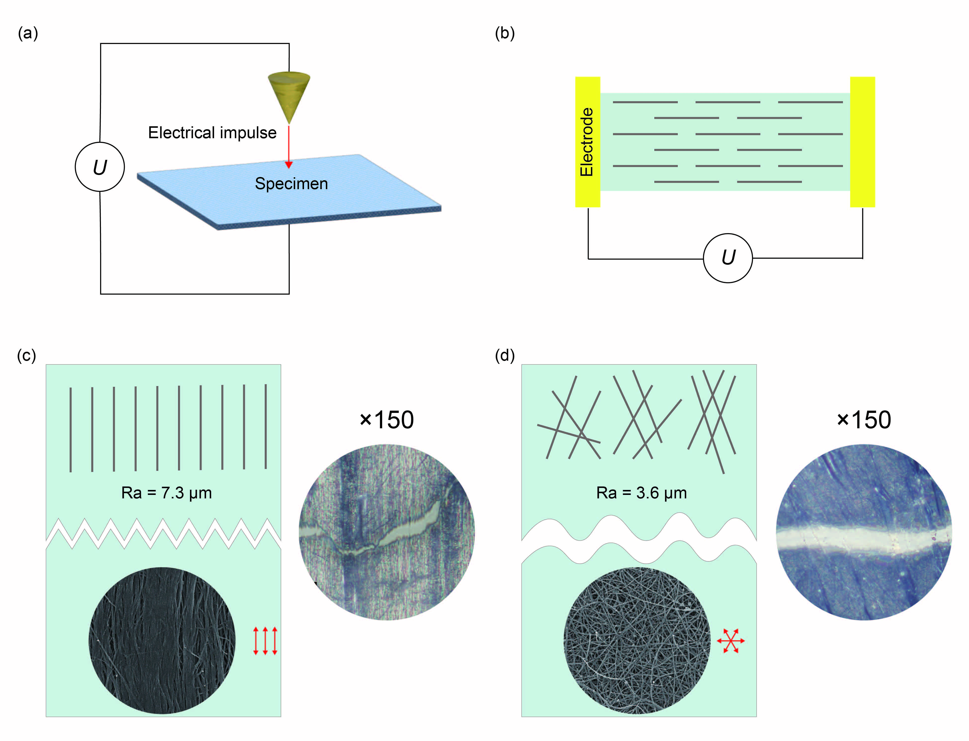
The structural responses and failure of CNT films under lightning strikes are experimentally simulated in an electrified platform, where a quartz substrate structurally supports the films (Fig. 1(a, b)). Quartz is chosen for its smooth surface, good thermal insulating properties, and thus the least perturbation to the fracture process. Electrical contacts are made by depositing silver to two opposite edges of films. Electric fields are then applied by using a direct current (DC) power source (Keithley 2480) with a voltage , where is the length of the film and is the electrical field. Experimental tests show that the films are destructed in a time scale of s, which is longer than the duration of a typical lightning strike [1, 2]. Post-destruction analysis using optical microscope (OM) images ( pixels/cm) is used to calculate the edge roughness . The crack morphologies of aligned CNT films are identified to be sharp and jagged with µm (Fig. 1(c)). In contrast, non-woven CNT films are destructed with a diffuse pattern of fracture with much smoother edges () µm (Fig. 1(d)).
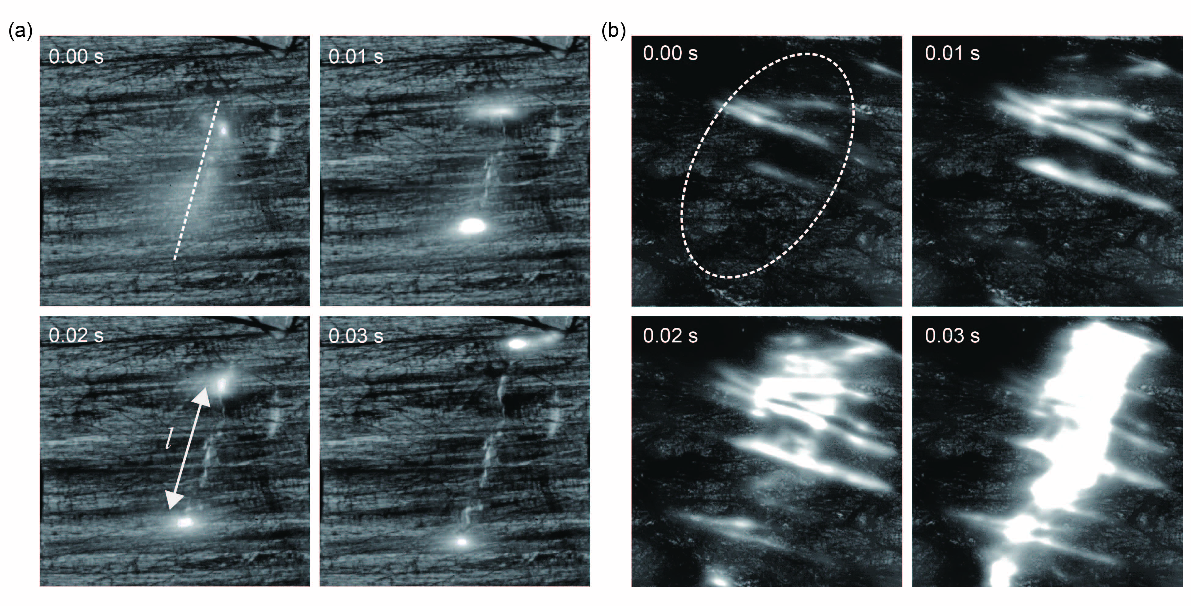
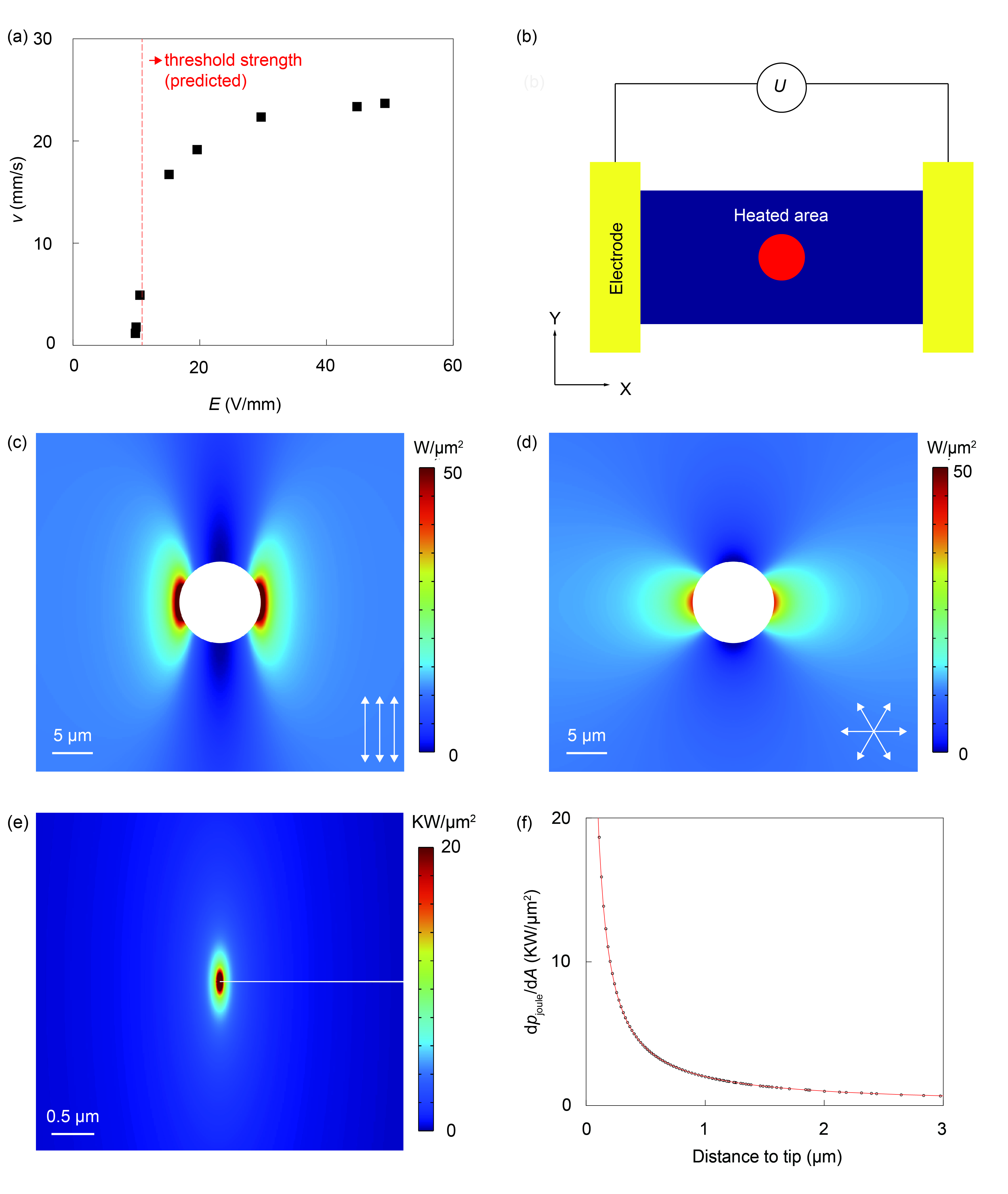
Progressive damage of the CNT films is recorded by using a high-speed camera (Photron FastCam mini UX100). An OM lens () is connected to the camera with a speed of flashes per second. From the videos taken during fracture (Fig. 2, Supplemental Videos S1 and S2), we find that in both aligned and non-woven samples, a flash emerges in the center of the specimen at seconds after power activation. The occurrence of flash signals energy concentration in the region or localized temperature rise and results in subsequent material damage by fracture. In the aligned CNT films, the luminous spots are localized at the crack tip and propagate along a straight line in the range of V/mm, leaving a crack wherever it passes (Fig. 2 (a)). The speed increases with the applied electric field after a threshold value of V/mm and gradually converges to mm/s beyond V/mm (Fig. 3 (a)). In contrast, the flash emerges from the central locus and expands uniformly in all orientations in the non-woven CNT films at a speed of mm/s, reflecting their isotropic nature. The fibers along the direction of the electric field show bright spots in the form of line segments, corresponding to the concentration of Joule heat (Fig. 2 (b)).
Physics and Theoretical Analysis - The coefficients of thermal expansion of CNTs remain as low as K-1 even as the temperature rises to K [33]. As a result, the maximum thermal stress in the film is far lower than the strength of CNTs, indicating that thermal stress will not lead to fracture. Buckling of slender CNTs may occur but it will not lead to fracture. Moreover, CNTs are covalently bonded materials, and electromigration does not play a key role in the destruction process compared to metals [34], especially within such a short duration (less than s). We conjecture that the local damage and destruction are induced by Joule heating. Balancing the areal rate of Joule heating () and that of thermal dissipation per unit area thus predicts the threshold field strength, . Beyond heat will be accumulated and fracture of the film is activated as observed in our experiments. Typically the failure will be nucleated at the center of the film [35] due to the boundary effect and at the defective sites with poor conductivities.
Following Joule’s law, the rate of heating is
| (1) |
where and are the thickness and electrical resistivity of the CNT films, respectively. On the other hand, heat dissipation of CNT films includes contributions from natural convective heat dissipation, , and radiative heat dissipation, , that is
| (2) |
where is the natural convective heat transfer coefficient. and are the temperatures of sample surfaces and ambient air, respectively. The radiative heat dissipation is determined by the Stefan-Boltzmann law, where and are the surface emissivity (), and the Stefan-Boltzmann constant ( Wm-2K-4). A threshold field strength can thus be estimated as
| (3) |
beyond which the Joule heating rate becomes higher than the maximum value of . Considering the breakdown (oxidization) temperature of CNT films in the air as K [34], the estimated value of shows agreement with the experimental data (Fig. 3(a)).
Above , the crack initiates from the destructed region (the central hole in Fig. 3(b)) and starts to propagate at a speed increasing with the Joule heat injected into the crack front. The heat concentration near the crack tip is simulated by finite element analysis (FEA). A 2D model with anisotropic thermal and electrical conductivities is constructed for the CNT films, which can be reduced to the isotropic one. The initial damage is modeled as a circular hole in the sample. The simulation results show the concentration of Joule heating near the damaged area (Fig. 3(c,d)). Compared with the isotropic, non-woven CNT films, there is a more intense concentration in the vicinity of the initial damage in aligned CNT films. The crack in the aligned CNT films thus propagates along a straight line, while in the non-woven film, the crack expands in a diffuse way.
By considering the anisotropic electrical conductivity in the aligned CNT films, the electrical potential can be solved from the governing Poisson equation
| (4) |
By rescaling the coordinates , where is the average conductivity, this equation can be transformed into . The boundary conditions of electrically insulating edges are enforced. The near-field field strength in polar coordinates is obtained as [36]
| (5) |
where measures the distance to the crack tip. and are the corresponding angle and crack length in the transformed coordinates. This result features a similar singularity as the stress field at the crack tip in LEFM. As shown in the coordinate transformation, the anisotropic conductivity enhances the field concentration at the crack tip. The rate of Joule heating in the vicinity of the crack tip thus exhibits a direct proportionality to the inverse of the distance from the crack tip, signaling heat concentration (Fig. 3(e, f)). In practice, the electrified at the crack tip cannot go to infinity due to the shielding effect originating from charge redistribution in the CNTs. An increase in will result in a higher heating rate, and a more rapid local destruction process (Fig. 3(a)), which saturates as the crack approaches the sample boundary.
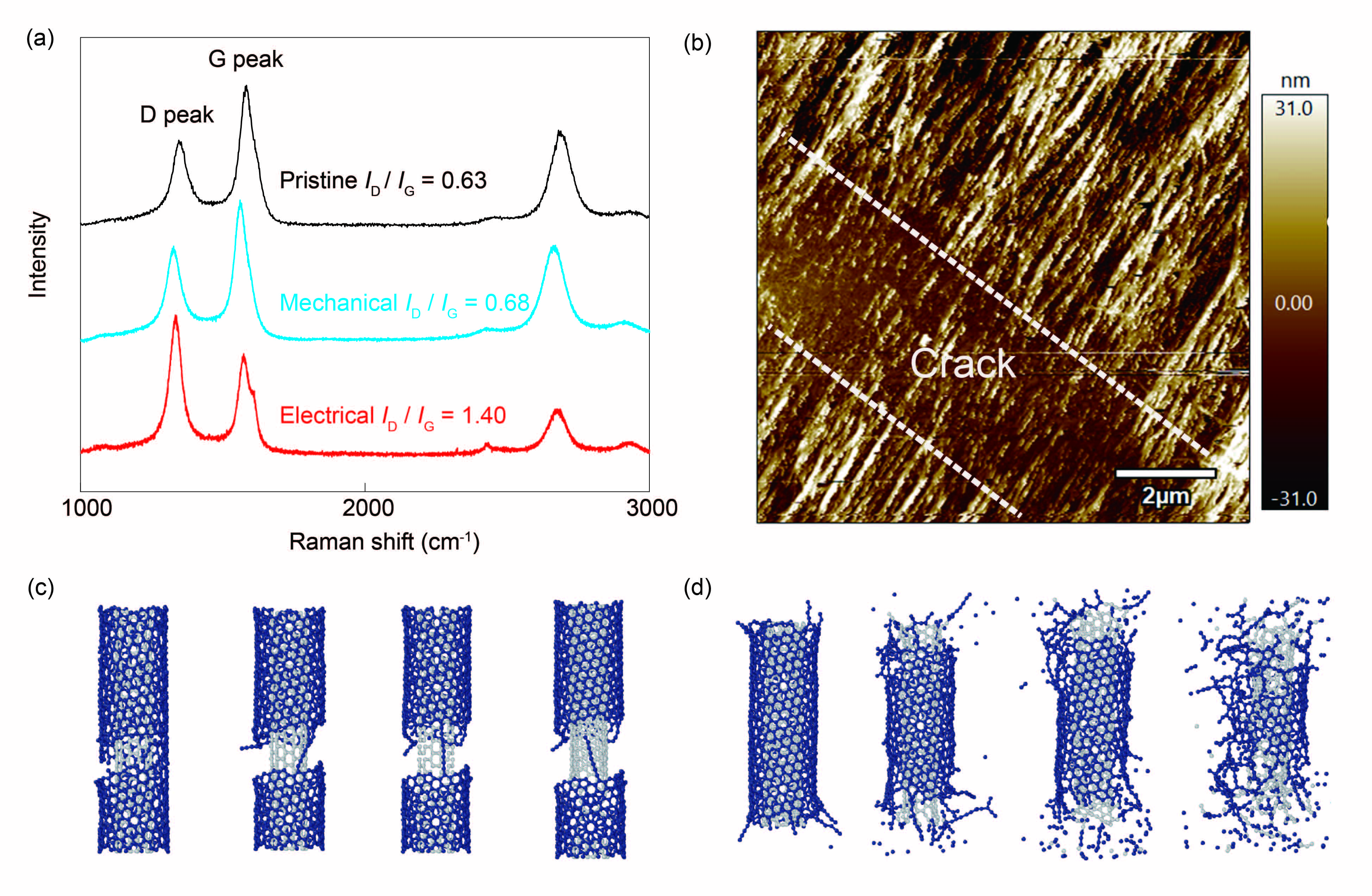
The fractured surfaces of aligned CNT films under electrification are further examined by Raman spectroscopy to elucidate the atomic-level processes occurring at the crack tip, and compared to the surfaces of cleaved mechanically (Fig. 4(a)). The results suggest a higher intensity of the ratio and thus a greater degree of atomic-scale disorder in the electrified samples. Atomic force microscopy (AFM) images at the crack tip resolve the crack features created by Joule heating, which show jagged patterns (Fig. 4(b)) and suggest a melting failure at the single-fiber level under electrification. We also carry out molecular dynamics (MD) simulations for direct evidence of these processes. Tensile- and electrification-induced fractures of double-walled CNTs (DWNTs) are modeled using the large-scale atomic/molecular massively parallel simulator (LAMMPS) [37] (Fig. 4(c, d)). The adaptive intermolecular reactive empirical bond order (AIREBO) potential [38] is used to model the interatomic interaction between carbon atoms in the DWNTs. Periodic boundary conditions are used with a supercell of nm. Joule heating is performed by raising the temperature from K to K at a rate of K/ns, and the strain rate of tensile loading is m/s, which is relatively low to reduce the rate dependence but still much higher than the experimental values due to the spatiotemporal limitation of MD simulations. The findings indicate that during tensile fracture, the DWNTs experience bond breakage, while the sp2 lattice remains unaltered. In contrast, the lattice melts under Joule heating.
In this study, we conduct a comparative analysis of the fracture patterns shown by aligned and non-woven CNT films. In terms of fracture edges, aligned CNT films exhibit a distinct and irregular morphology, characterized by sharp and jagged features. In contrast, the edges of the non-woven CNT films appear to be more refined and less rough. Aligned CNT films demonstrate a linear, tip-guided fracture propagation mode, whereas non-woven CNT films display a diffusive mode. Numerical simulations and theoretical analysis show that the observed discrepancy can be attributed to the pronounced anisotropic conductivity of the aligned CNT films. This characteristic gives rise to a significant heat accumulation around the edges of the initially damaged hole in the aligned CNT films. We then theoretically demonstrated the existence of a singular temperature field near the crack tips, which guides the dynamics of cracking and defines the fracture patterns. The arguments exhibit a favorable agreement with the outcomes obtained from the experimental and simulation results. The fracture patterns of the aligned CNT films are further examined by Raman spectroscopy, AFM characterization, and MD simulations, validating that the fracture in electrified films is generated by Joule heating and is very different from force-induced fracture.
This study was supported by the National Natural Science Foundation of China through grants 52090032 and 11825203, and the National Key Basic Research Program of China grant No. 2022YFA1205400. The computation was performed on the Explorer 100 cluster system of the Tsinghua National Laboratory for Information Science and Technology.
References
- Larsson [2002] A. Larsson, The interaction between a lightning flash and an aircraft in flight, Comptes Rendus. Physique 3, 1423 (2002).
- Kumar et al. [2020] V. Kumar, T. Yokozeki, C. Karch, A. A. Hassen, C. J. Hershey, S. Kim, J. M. Lindahl, A. Barnes, Y. K. Bandari, and V. Kunc, Factors affecting direct lightning strike damage to fiber reinforced composites: A review, Compos. Part B: Eng. 183, 107688 (2020).
- Uman and Rakov [2003] M. Uman and V. Rakov, The interaction of lightning with airborne vehicles, Prog. Aero. Sci. 39, 61 (2003).
- Gagné and Therriault [2014] M. Gagné and D. Therriault, Lightning strike protection of composites, Prog. Aero. Sci. 64, 1 (2014).
- Dresselhaus et al. [1998] G. Dresselhaus, M. S. Dresselhaus, and R. Saito, Physical Properties of Carbon Nanotubes (World scientific, 1998).
- De Volder et al. [2013] M. F. De Volder, S. H. Tawfick, R. H. Baughman, and A. J. Hart, Carbon nanotubes: present and future commercial applications, Science 339, 535 (2013).
- Kinloch et al. [2018] I. A. Kinloch, J. Suhr, J. Lou, R. J. Young, and P. M. Ajayan, Composites with carbon nanotubes and graphene: An outlook, Science 362, 547 (2018).
- Hirano et al. [2010] Y. Hirano, S. Katsumata, Y. Iwahori, and A. Todoroki, Artificial lightning testing on graphite/epoxy composite laminate, Compos. Part A: Appl. Sci. Manuf. 41, 1461 (2010).
- Bai et al. [2023a] Y. Bai, M. Zhu, S. Wang, F. Gao, R. Gao, Y. Qu, X. Cui, G. Wang, L. Liu, H. Zhang, et al., Mechanism study of advanced lightning strike protection composite systems using a miniature tip discharge system, Compos. Part A: Appl. Sci. Manuf. 167, 107394 (2023a).
- Bai et al. [2023b] Y. Bai, M. Zhu, S. Wang, F. Gao, R. Gao, C. Wang, G. Wang, H. Jin, L. Liu, H. Zhang, and Z. Zhang, Superaligned carbon nanotube film/quartz fiber composites towards advanced lightweight lightning strike protection, Compos. Part A: Appl. Sci. Manuf. 173, 107617 (2023b).
- Huntington and Grone [1961] H. Huntington and A. Grone, Current-induced marker motion in gold wires, J. Phys. Chem. Solids 20, 76 (1961).
- Subramaniam et al. [2013] C. Subramaniam, T. Yamada, K. Kobashi, A. Sekiguchi, D. N. Futaba, M. Yumura, and K. Hata, One hundred fold increase in current carrying capacity in a carbon nanotube-copper composite, Nat. Commun. 4, 2202 (2013).
- Lawn [1993] B. R. Lawn, Fracture of Brittle Solids (Cambridge University Press, 1993).
- Yang [2003] W. Yang, Mechatronic Reliability: Electric failures, Mechanical-Electrical Coupling, Domain Switching, Mass-Flow Instabilities (Springer Science & Business Media, 2003).
- Liu [2008] T. Liu, Thermo-electro-structural coupled analyses of crack arrest by joule heating, Theor. Appl. Fract. Mech. 49, 171 (2008).
- Westover et al. [2009] T. Westover, R. Jones, J. Huang, G. Wang, E. Lai, and A. A. Talin, Photoluminescence, thermal transport, and breakdown in joule-heated gan nanowires, Nano Lett. 9, 257 (2009).
- Zhao et al. [2011] J. Zhao, H. Sun, S. Dai, Y. Wang, and J. Zhu, Electrical breakdown of nanowires, Nano Lett. 11, 4647 (2011).
- Song et al. [2020] H. Song, K. Xie, and C. Gao, Progressive thermal stress distribution around a crack under joule heating in orthotropic materials, Appl. Math. Model. 86, 271 (2020).
- Black [1969] J. R. Black, Electromigration: A brief survey and some recent results, IEEE Trans. Electron Devices 16, 338 (1969).
- Ho and Kwok [1989] P. S. Ho and T. Kwok, Electromigration in metals, Rep. Prog. Phys. 52, 301 (1989).
- Xu et al. [2016] W. Xu, Y. Chen, H. Zhan, and J. N. Wang, High-strength carbon nanotube film from improving alignment and densification, Nano Lett. 16, 946 (2016).
- Guo et al. [2022] Y. Guo, E. Shi, J. Zhu, P.-C. Shen, J. Wang, Y. Lin, Y. Mao, S. Deng, B. Li, J.-H. Park, et al., Soft-lock drawing of super-aligned carbon nanotube bundles for nanometre electrical contacts, Nat. Nanotechnol. 17, 278 (2022).
- Ericson et al. [2004] L. M. Ericson, H. Fan, H. Peng, V. A. Davis, W. Zhou, J. Sulpizio, Y. Wang, R. Booker, J. Vavro, C. Guthy, et al., Macroscopic, neat, single-walled carbon nanotube fibers, Science 305, 1447 (2004).
- Puchades et al. [2015] I. Puchades, C. C. Lawlor, C. M. Schauerman, A. R. Bucossi, J. E. Rossi, N. D. Cox, and B. J. Landi, Mechanism of chemical doping in electronic-type-separated single wall carbon nanotubes towards high electrical conductivity, J. Mater. Chem. C 3, 10256 (2015).
- Han et al. [2017] B. Han, X. Xue, Y. Xu, Z. Zhao, E. Guo, C. Liu, L. Luo, and H. Hou, Preparation of carbon nanotube film with high alignment and elevated density, Carbon 122, 496 (2017).
- Taylor et al. [2021] L. W. Taylor, O. S. Dewey, R. J. Headrick, N. Komatsu, N. M. Peraca, G. Wehmeyer, J. Kono, and M. Pasquali, Improved properties, increased production, and the path to broad adoption of carbon nanotube fibers, Carbon 171, 689 (2021).
- Wang et al. [2021] S. Wang, J. Lin, Z. Xu, and Z. Xu, Understanding macroscopic assemblies of carbon nanostructures with microstructural complexity, Compos. Part A: Appl. Sci. Manuf. 143, 106318 (2021).
- Jiang et al. [2011] K. Jiang, J. Wang, Q. Li, L. Liu, C. Liu, and S. Fan, Superaligned carbon nanotube arrays, films, and yarns: a road to applications, Adv. Mat. 23, 1154 (2011).
- Chen et al. [2016] H. Chen, L. Zhang, J. Chen, M. Becton, X. Wang, and H. Nie, Effect of cnt length and structural density on viscoelasticity of buckypaper: A coarse-grained molecular dynamics study, Carbon 109, 19 (2016).
- Liu et al. [1998] J. Liu, A. G. Rinzler, H. Dai, J. H. Hafner, R. K. Bradley, P. J. Boul, A. Lu, T. Iverson, K. Shelimov, C. B. Huffman, et al., Fullerene pipes, Science 280, 1253 (1998).
- Kim et al. [2006] Y. A. Kim, H. Muramatsu, T. Hayashi, M. Endo, M. Terrones, and M. S. Dresselhaus, Fabrication of high-purity, double-walled carbon nanotube buckypaper, Chem. Vap. Depos. 12, 327 (2006).
- Gao et al. [2018] E. Gao, W. Lu, and Z. Xu, Strength loss of carbon nanotube fibers explained in a three-level hierarchical model, Carbon 138, 134 (2018).
- Jiang et al. [2004] H. Jiang, B. Liu, Y. Huang, and K. Hwang, Thermal expansion of single wall carbon nanotubes, J. Eng. Mater. Technol. 126, 265 (2004).
- Bai et al. [2023c] Y. Bai, M. Zhu, S. Wang, L. Liu, and Z. Zhang, Dynamic electrical failure of carbon nanotube ribbons, Carbon 202, 425 (2023c).
- Liu et al. [2016] P. Liu, Z. Fan, A. Mikhalchan, T. Q. Tran, D. Jewell, H. M. Duong, and A. M. Marconnet, Continuous carbon nanotube-based fibers and films for applications requiring enhanced heat dissipation, ACS Appl. Mater. Interfaces 8, 17461 (2016).
- Hua-lin and Ping [2005] F. Hua-lin and C. Ping, Crack arrest effect in thin plates, Acta Armamentarii 26, 791 (2005).
- Thompson et al. [2022] A. P. Thompson, H. M. Aktulga, R. Berger, D. S. Bolintineanu, W. M. Brown, P. S. Crozier, P. J. in’t Veld, A. Kohlmeyer, S. G. Moore, T. D. Nguyen, et al., LAMMPS: A flexible simulation tool for particle-based materials modeling at the atomic, meso, and continuum scales, Comput. Phys. Commun. 271, 108171 (2022).
- Stuart et al. [2000] S. J. Stuart, A. B. Tutein, and J. A. Harrison, A reactive potential for hydrocarbons with intermolecular interactions, J. Chem. Phys. 112, 6472 (2000).