Power Optimization in Satellite Communication Using Multi-Intelligent Reflecting Surfaces
Abstract
This study introduces two innovative methodologies aimed at augmenting energy efficiency in satellite-to-ground communication systems through the integration of multiple Reflective Intelligent Surfaces (RISs). The primary objective of these methodologies is to optimize overall energy efficiency under two distinct scenarios. In the first scenario, denoted as Ideal Environment (IE), we enhance energy efficiency by decomposing the problem into two sub-optimal tasks. The initial task concentrates on maximizing power reception by precisely adjusting the phase shift of each RIS element, followed by the implementation of Selective Diversity to identify the RIS element delivering maximal power. The second task entails minimizing power consumption, formulated as a binary linear programming problem, and addressed using the Binary Particle Swarm Optimization (BPSO) technique. The IE scenario presupposes an environment where signals propagate without any path loss, serving as a foundational benchmark for theoretical evaluations that elucidate the system’s optimal capabilities. Conversely, the second scenario, termed Non-Ideal Environment (NIE), is designed for situations where signal transmission is subject to path loss. Within this framework, the Adam algorithm is utilized to optimize energy efficiency. This non-ideal setting provides a pragmatic assessment of the system’s capabilities under conventional operational conditions. Both scenarios emphasize the potential energy savings achievable by the satellite-RIS system. Empirical simulations further corroborate the robustness and effectiveness of our approach, highlighting its potential to enhance energy efficiency in satellite-to-ground communication systems.
I Introduction
Satellite communication systems have been a cornerstone of global telecommunications for several decades, providing essential services such as broadcasting, navigation, and remote sensing. However, the inherent challenges of satellite communication, such as long propagation delays, signal attenuation, and interference, have motivated continuous research and development efforts to enhance system performance and reliability. Reconfigurable Intelligent Surfaces (RISs) have recently garnered significant attention as a potential cornerstone for the next generation of wireless communication networks [1]. Essentially, an RIS is a synthetic surface laden with a vast array of cost-effective, reconfigurable passive reflecting elements. These elements have the capability to modify the trajectory of incoming wireless signals by fine-tuning their amplitude and phase shift [2]. One of the standout features of RISs is their independence from radio frequency (RF) chains. This independence translates to a substantial decrease in energy usage and hardware expenses, positioning RISs as a more cost-effective and eco-friendly alternative to traditional multi-antenna and relaying systems [3, 4]. Given these attributes, RISs are emerging as a streamlined and cost-efficient solution for achieving wireless communication that boasts high spectral and energy efficiencies. This potential has ignited a surge of interest from both the commercial and academic sectors, all eager to harness the full spectrum of benefits that RISs offer.
Related Works
Research Insights into Single RIS-Aided Terrestrial Systems
The domain of single RIS-aided systems has been thoroughly explored in various studies [5, 6, 3, 7, 8, 9, 10, 11]. A comparative analysis in [5] demonstrates that RIS outperforms conventional massive multiple-input multiple-output systems and multi-antenna amplify-and-forward (AF) relaying networks, offering advantages in system complexity and cost reduction. Reference [6] provides insight into the basic characteristics of RIS/antenna technology and explores its potential applications. In [3], the authors present a comprehensive overview of state-of-the-art solutions, highlight fundamental distinctions between RIS and other technologies, and discuss pivotal open research issues in this field. The utilization of RIS to enhance the quality of source signals transmitted to a destination via an unmanned aerial vehicle is explored in [[7]. Study [8] investigates the performance of an RIS-assisted mixed indoor visible light communication/radio frequency (RF) system, deriving closed-form expressions for Outage Probability (OP) and bit error rate (BER) for both AF and decode-and-forward (DF) relaying schemes. In [9], the secrecy OP of an RIS-assisted network is derived, considering the presence of a direct link and an eavesdropper. Conversely, [10] derives accurate approximations for channel distributions and performance metrics of RIS-assisted networks, assuming Rayleigh fading channels and applicability to any number of reflecting elements. More recently, [11] provided closed-form expressions for the bit error probability of RIS-assisted networks over Nakagami-m fading channels. They noted that their results are primarily valid for BPSK and QAM modulation techniques. While the authors in [11] considered Nakagami-m fading channels, their exact expressions for error probability were confined to a limited number of reflecting elements.
Multiple RISs-Aided terrestrial station
Diverging from the exploration of single RIS-aided networks, several scholarly works have delved into analyses involving multiple RISs. Pertinent literature in this domain can predominantly be classified into two main categories: those focusing on optimization and those centered on performance analysis. In the optimization category, [12] introduces a novel approach, exploiting the line-of-sight (LoS) link between adjacent RISs to establish a multi-hop cascaded LoS link between the base station (BS) and the user. In this context, a set of RISs are strategically selected to sequentially reflect the BS’s signal, thereby maximizing the received signal power at the user. However, it’s crucial to note that this study exclusively considered the impact of path-loss, omitting the potential impact of fading. Conversely, a more recent contribution to this category is [13], which explored the optimization of RIS-aided networks by deploying multiple RISs to cater to wireless users. The researchers sought to enhance the network’s energy efficiency by dynamically adjusting the operational status of each RIS and fine-tuning the reflection coefficients matrix. For further exploration into optimization challenges within RIS-aided networks that utilize multiple RISs, [14] and [15] provide additional perspectives and findings.
Meanwhile, the utilization of multiple RISs can enhance communication systems by providing numerous paths for received signals, thereby amplifying the received signal strength. The outage probability in systems assisted by multiple RISs was scrutinized and optimized in [16]. In [17], the authors explored the use of multiple RISs to maximize the received power for downlink point-to-point millimeter-wave communications. Considering multi-hop transmission through RIS, the design of double-hop assisted wireless communication was investigated in [18] and [19]. Furthermore, the multi-cell network with multiple RISs was examined in [20], taking into account non-orthogonal multiple access. By concurrently considering uplink and downlink, the weighted sum rate maximization problem for multi-RIS-assisted full-duplex systems was studied in [21]. However, the aforementioned works [16]-[21] presupposed that all RISs are operational, which is not energy-efficient since RISs also consume energy for signal controlling.
RISs-Aided Satellites Systems
Effective communication between satellites and terrestrial stations is paramount for the transmission of data across extensive distances. With the proliferation of satellites and an escalation in data transmission requirements, it is imperative to augment the energy efficiency of these communication systems. Satellites, predominantly powered by photovoltaic cells and energy storage units, necessitate meticulous energy management to prolong their operational lifespan. In an epoch where extended satellite operability and sustainability are of paramount importance, the enhancement of energy efficiency is indispensable.
A pragmatic approach to optimize energy utilization in satellite systems involves the refinement of the ground segment of the communication architecture. By augmenting signal processing capabilities at terrestrial stations, it becomes feasible to decode attenuated signals emanating from satellites. Consequently, satellites can operate at reduced power levels, thereby conserving energy while concurrently ensuring robust and reliable communication. This methodology underpins the sustainable functionality of satellite systems and guarantees the integrity of data transmission, thereby upholding the efficacy of global communication networks. In recent advancements, the integration of Reflecting Intelligent Surfaces (RISs) into satellite communication frameworks has been proposed, offering an auxiliary indirect path for signal transmission concomitant with the direct Line-of-Sight (LoS) link from satellites. This integration has the potential to fortify the received signal and mitigate the effects of environmental perturbations [22]. While studies like [23, 24, 25] and [26] have highlighted the benefits of RISs in terrestrial wireless communication, there is limited academic research on their use in satellite communication systems. The unique characteristics of satellite communications, encompassing global coverage, protracted propagation distances, and the spherical geometry of Earth, present novel challenges and opportunities for the implementation of RISs [27]. The scarcity of research specifically addressing the integration of RISs in satellite systems underscores a significant gap in the current body of knowledge, emphasizing the need for further exploration in this innovative domain.
Contribution
Energy Efficiency () is defined as the ratio of power received by the system to its total power consumption [28]. While the energy efficiency of RIS-aided satellites has been explored to some extent, comprehensive research in this domain remains sparse in the extant literature. This investigation endeavors to address this lacuna by proposing a new model tailored to augment the energy efficiency of multi-RIS-aided satellite communication systems. Several determinants influence in RIS-aided satellites, encompassing the power expended per reflecting element, RIS phase shifting consumption, control power operation, and the energy requisitioned by the associated circuitry. It is salient to note that the predominant power consumption in an RIS emanates from its reflecting elements. As delineated by [29], each RIS reflection element necessitates approximately 0.33 mW of power. Consequently, the incorporation of multiple RISs invariably escalates consumption due to the augmented count of reflecting elements. In light of this backdrop, the present manuscript elucidates an optimization framework dedicated to amplifying the system’s energy efficiency. This is achieved through the deployment of two distinct methodologies under varied environmental paradigms, thereby enriching the academic discourse with diverse optimization techniques.
First Method: Ideal Environment (IE)
In the Idle Environment (IE) method, we propose an optimization scheme that presupposes an environment devoid of perturbations. Here, "IE" denotes a scenario wherein the signal, emanating from both the satellite and the RIS panel and directed towards the user, remains unimpeded by path-loss, shadowing, and other factors that could impact signal propagation. The optimization of Energy Efficiency () in this context is delineated into two sub-problems: the maximization of power received by the end-user and the minimization of the overall power expenditure. This bifurcation facilitates a more granular analysis, thereby enabling the formulation of targeted solutions that strike an equilibrium between performance and . To optimize power reception in the IE method, we introduce a methodology to calculate the received power, accounting for both the Line-of-Sight (LoS) and the RIS-reflected components. Subsequently, we employ this initial computation to ascertain the optimal phase shifts for each RIS, with the aim of achieving maximal power reception. Utilizing Selective Diversity (SD), we identify the RIS configuration that yields the highest power reception. Conversely, the minimization of power consumption, predominantly attributed to the reflecting elements, is formulated as a binary linear programming problem. In addressing this challenge, we employ the Binary Particle Swarm Optimization (BPSO) algorithm, acclaimed for its efficacy in navigating complex solution spaces to identify optimal configurations. Upon the concurrent maximization of power reception and minimization of power consumption, we deduce the optimal energy efficiency.
Second Method: Non-Ideal Environment (NIE)
Within the Non-Ideal Environment (NIE) framework, we consider both deterministic and stochastic components of signal path loss. Deterministic path loss predominantly arises from signal attenuation, influenced by factors such as transmission distance and medium-specific properties, including air or vacuum. Conversely, stochastic path loss is attributed to shadowing and various unpredictable environmental dynamics. For the optimization of in the NIE context, we utilize the Adam algorithm, a methodology originally conceptualized for neural networks by [30]. In its foundational application, the Adam algorithm measures the divergence between predicted and actual outputs, typically denoted as a loss, serving as the objective function. The algorithm capitalizes on moving averages of the parameters, termed momentums, to expedite optimization. Moreover, its adaptive learning rates, which adjust based on historical gradient data, ensure meticulous convergence towards the optimal solution.
In the context of our proposed system, the primary objective is to enhance . In this endeavor, the attributes of the Adam algorithm, specifically its adaptive learning rates and momentum components, prove invaluable. These features facilitate the accurate calibration of optimal parameter values, potentially offering a more efficient approach than conventional optimization methods. Considering the complexity of the proposed system, which comprises multiple RISs, each with an array of reflection elements, the proficiency of the Adam algorithm in navigating complex optimization challenges is manifest. Given these considerations, we have adapted the Adam algorithm into a unique strategy designed to estimate energy efficiency in RIS-aided satellite networks, especially under NIE conditions. The outcomes from this approach validate the algorithm’s proficiency in RIS-centric scenarios, and our simulation results provide additional validation of its reliability.
The structure of this paper is as follows: Section II presents the system model, elaborating on the components and configuration of the RIS-assisted communication system. Section III articulates our proposed formulation for energy efficiency, encompassing both the received power and power consumption metrics. Section IV, emphasizes the optimization of the RIS phase shift under ideal conditions, elucidating the methodologies and techniques employed to optimize energy efficiency. Section V explores the intricacies of non-ideal scenarios, with a particular focus on the implications of path-loss and environmental uncertainties on received power. The paper concludes with Section VI, which synthesizes our findings and proposes potential directions for future research and advancements in the domain of RIS-assisted wireless communication systems.
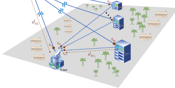
II System Model
In this study, we present a satellite communication system designed to transmit data to a terrestrial user. This system incorporates multiple Reflecting Intelligent Surfaces (RISs) situated on the Earth’s surface to facilitate the relay of the satellite signal to the user. communications. Each RIS is composed of elements, which can be dynamically adjusted to modulate both the phase and amplitude of the reflected electromagnetic waves, thereby creating an indirect transmission route that complements the LOS link arriving directly from satellite communications. As illustrated in Fig. (1), the system’s configuration adopts a triangular arrangement that includes the Satellite (S), the User receiver (U), and a designated terrestrial RIS. Within this arrangement, the signal propagation paths are defined as: (from S to each RIS), (direct path from S to U), and (from each RIS to U). Given the global reach of satellite communications and taking into account the Earth’s spherical geometry, we apply spherical trigonometry to determine the distances associated with signal propagation [31]. The Cartesian coordinates of each RIS () and the user ) are utilized to derive their corresponding geographic coordinates (latitude and longitude). The coordinates for the RIS are determined as:
| (1) |
where the is an index that uniquely identifies each RIS and is defined as , where represents the total number of RISs in the system. The terms lat and lon denote the latitude and longitude of the respective locations, and signifies the Earth’s radius. By employing the Cartesian coordinates of each RIS and the user, we can determine the Euclidean distance between each RIS and the user receiver
| (2) |
To deduce the total power received from both the direct LOS link and any RISs, we commence by evaluating the power of the LOS signal arriving at the ground receiver, denoted as U. It is assumed that all the channel information from each RIS and the LOS link is available at the user node. The power received by U is influenced by factors such as the propagation distance , the transmission frequency, and atmospheric attenuation. Consequently, the expression which encapsulates the complex amplitude of the signal from the satellite to the user, incorporating both amplitude and phase information, is articulated by
| (3) |
In the given expression, denotes the transmitted signal power, is the path loss (PL) between S and U, while and represent the gains of the transmitter and receiver antennas, respectively. The phase of the direct received signal is represented by , and is defined as
| (4) |
The path loss between S and U primarily arises from free space propagation, and can be expressed in decibels using the following expression:
| (5) |
where is the frequency in , is the wavelength, and is a random variable captures the additional PL arising from ground clutter, including structures like buildings, vegetation, and terrain [32]. It’s noteworthy that when considering the RIS, which typically maintains a clear path to the satellite, the shadowing effect (or additional PL) due to such obstacles is negligible. The direct signal path from to the user, , is characterized by both amplitude and phase, represented as:
| (6) |
where is given by: and is accompanied by its phase shift
The trajectory of a signal incident on the RIS is is primarily determined by the distance For each RIS in the system (where ranges from 1 to ), the incident signal can be comprehensively described by:
| (7) |
Here, denotes the antenna gain at the th element of the RIS, corresponding to the angles of incidence . The phase characterizes the phase of the signal upon reaching the RIS and is defined as: Furthermore, represents the path loss between the S and the specific RIS. When expressed in decibels, this path loss is given by:
| (8) |
In this expression, is defined to have the same characteristics as
The interaction of a signal with a given RIS is determined by several factors. These encompass the angle of incidence, signal polarization, the distance from the S to a specific RIS, denoted as , and the distance from that RIS to the user receiver, indicated by .
The complex amplitude of the signal reflected from any RIS, notated as , is determined by:
| (9) |
In this formulation, signifies the phase induced by each element of the RISs, represents the reflected antenna gain of the element of the RISs, correlated to the reflected angle and illustrates the reflection coefficient for an RIS, indicating the portion of the incident signal’s power that’s reflected by the element within each RIS, as discussed in [4]. The phase-shifting capability of each RIS panel, denoted by , plays a pivotal role in the system. This capability to modulate the signal phase can induce either constructive or destructive interference at the receiving terminal. Under the assumption that there are no multi-path signals originating from any RIS to the receiver, the complex amplitude of the signal received by U is given by:
| (10) |
where represents the phase of the indirectly received signal and is defined by the equation and , denotes the path loss between a specific RIS and the user U and can be expressed as
| (11) |
In this equation, is a random variable representing the shadow fading effect between any RIS and the user. This shadow fading is characterized by a log-normal distribution: , where , and are the mean and standard deviation of the shadow fading effect for any , respectively. Drawing upon the amplitude expression from (10), we derive
| (12) |
with the total phase being: .
Now, simplifying the expression for we get:
| (13) |
Let us define the overall amplitude of the signal at the user from all the RIS elements as: and the phase of the total signal at the user from all the RIS elements as:
| (14) |
where the function extracts the phase angle of a complex number. This essentially captures the overall phase shift experienced by the signal as it interacts with all the RIS elements and reaches the user. However, to delve deeper and understand the phase contributions from each individual RIS element, we can represent these individual phases in a vector format. For each RIS element, indexed by and , the phase is given by . Collectively, these phases can be represented as a vector:
| (15) |
Each element in the vector represents the phase shift introduced by a specific RIS element. By examining this vector, we can glean insights into how each RIS element contributes to the overall phase of the received signal.
The total signal received at the user is the summation of both the direct path from the satellite and the reflected paths from all the RISs, represented as The received power, , is then determined by squaring the magnitude of this combined signal:
| (16) |
For any complex number , the squared magnitude is given by,, where denotes the complex conjugate of Utilizing this property, the received power can be expanded as:
| (17) |
Breaking down the terms in (17) as
| (18) |
where and represent the cross-terms, indicating the interaction between the direct signal and the RIS-reflected signal. Using properties of complex multiplication, this interaction is defined as: These cross-terms encapsulate the interference effects between the direct and RIS-reflected signals, accounting for both amplitude and phase differences. In particular, the real part of this product captures the nature of this interference, signifying whether the signals constructively or destructively interfere. Hence, the received power can be succinctly represented as:
| (19) |
Thus, the received power is a function of various factors, including phase shifts, propagation distances, and external environmental influences represented by path loss.
III Energy Efficiency
The incorporation of RISs into contemporary wireless communication architectures has been identified as a promising avenue for bolstering overall system performance. In scenarios where the system comprises distinct RISs, each equipped with reflecting elements, the metric of energy efficiency becomes crucial for a comprehensive assessment of the system’s effectiveness [13]. As delineated by [28, p. 2484], energy efficiency is represented as the ratio of the total power received by the system to its overall power consumption. In formal terms, energy efficiency can be expressed as:
| (20) |
In (20) formulation, the term represents the power consumed by each RIS system’s circuitry. Assuming all the RISs have approximately the same , then . The variable denotes the state of the element in the RIS. Specifically, signifies that the reflecting element in the RIS is active, whereas indicates it is inactive. The terms and indicate the power consumed for phase shifting and control operations, respectively, for the element of the RIS. The term encapsulates the notion that power consumption for phase shifting and control may vary across elements and RISs. In our study, equation serves as the reference or baseline model, representing the standard approach in the field. Within this model, the term (19) is defined as per (19). Notably, this baseline does not account for advanced techniques such as phase optimization, or the implementation of selective diversity.
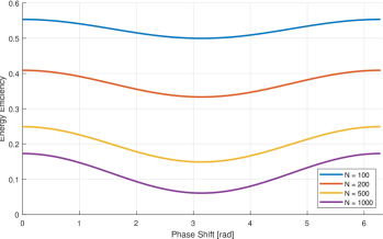
Fig. 2 depicts the baseline energy efficiency of a system that incorporates four RISs. For the sake of simplification, we assume that all RIS elements have a uniform phase shift. The graph indicates a decline in energy efficiency as the number of reflecting elements, , increases. This decline can be attributed to the increased power consumption by the RISs, especially during phase shifting and the control of additional elements. Consequently, this amplifies the denominator in the equation, leading to a reduction in overall energy efficiency. Such observations emphasize the inherent trade-off between system performance and energy consumption. It underscores the importance of judiciously selecting the number of reflecting elements in RIS-integrated communication systems, even before the implementation of any optimization techniques.
Subsequently, our primary aim is to optimize energy efficiency, which intrinsically reduces power consumption while concurrently enhancing received power. To achieve this, we deconstruct (20) into two sub-optimal problems: maximization of received power and minimization of power consumption, . In this study, maximization is introduced into two scenarios. The first scenario considered ideal conditions, assuming no path loss, while the second one incorporates the path loss.
IV Maximize under ideal conditions
The primary objective of the proposed method is to optimize the phase shift, , to enhance over a specified distance range. Given that is an element of the phase vector , and considering that other components (i.e., and ) are known, the main focus shifts to the optimization of . By achieving this, we can effectively cover a broader range of users or areas. As previously mentioned, maximizing entails maximizing and minimizing the denominator of .
The received power, , depends on several factors, including the transmitted power, the gains of the transmitting and receiving antennas, the path loss, and the phase shifts introduced by the RIS elements. In the absence of path loss, the received power is predominantly influenced by the direct LOS path and the paths associated with the RISs. The interference effect between the direct and RIS-reflected signals is encapsulated by the term . The goal is to adjust the phase shifts to ensure this interference is constructive, thereby augmenting the received power. To identify the optimal phase shifts that maximize we employ differential calculus. Differentiating with respect to provides:
| (21) |
To maximize , the derivative should be set to zero, yielding the condition: , where, is an integer. This equation delineates the optimal phase shifts that ensure the received power is at its peak. Essentially, the phase shifts must be adjusted so that the direct and RIS-reflected signals are in phase. This alignment results in constructive interference, leading to an enhanced received power.
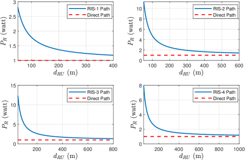
To validate (21), we assess the power received from each individual RIS, treating each case as if . Fig. 3 presents a detailed comparison of the received power when utilizing four RISs versus a direct path over a range of distances. Each subplot is associated with a distinct RIS, differentiated by its proximity to the user. The data suggests that the received power is influenced by several factors, such as the distance between the RIS and the user, the number of elements in each RIS, and the phase shifts introduced by the RIS. The red dashed line in each subplot represents the power received via the direct path, serving as a benchmark for comparison. On the other hand, the continuous lines illustrate the power received with the aid of each RIS. A side-by-side comparison of the continuous and dashed lines clearly demonstrates the potential of an RIS to either enhance or reduce the received power relative to the direct transmission path.
Given a system with multiple paths (or channels) through which a signal can reach a receiver, represented as selective diversity can be employed to choose the path with the highest signal power. This can be mathematically expressed as:
| (22) |
where represents the selected power among RISs.
The secondary objective focuses on minimizing the cumulative power consumption, represented as: . To augment power efficiency across the circuitry and individual RIS elements, several pivotal tactics warrant consideration. One such strategy entails the selective deactivation of certain RIS elements deemed non-essential, facilitating power conservation. Furthermore, meticulous scrutiny and optimization of control operations can yield energy-efficient management, curtailing power expenditure without sacrificing system efficacy. On a more granular level, hardware-centric enhancements offer avenues for superior energy efficiency. This can be achieved by diminishing the intrinsic power consumption of each RIS element, either through the adoption of energy-conserving materials or advancements in thermal management. Consequently, the optimization objective can be articulated as:
| (23) |
The primary objective now is purely to reduce the power consumed by the RISs. Since is binary, the optimization will find the optimal configuration of active and inactive reflecting elements to achieve this objective. The problem defined in (23) is characterized as a binary linear programming issue. While there exist efficient solvers tailored for such challenges, the computational burden significantly rises with an increase in the number of RISs and elements number As a result, resorting to heuristic or metaheuristic strategies, such as greedy algorithms and genetic algorithms, could offer a more feasible approach. However, Particle Swarm Optimization (PSO) stands out among these methods due to its unique ability to concurrently explore and exploit the solution space. Its collaborative nature enables particles to learn from both individual and global best solutions, ensuring rapid convergence. Moreover, when adapted for binary contexts using Binary PSO (BPSO) techniques, PSO demonstrates enhanced scalability and efficiency with minimal parameter tuning, marking it as an optimal choice for such optimization challenges [33].
Given RISs, where each RIS has reflecting elements, we can represent the state (either active or inactive) of each element using a binary matrix. The dimensionality of our swarm is determined by the total number of variables in our problem, which is . In the PSO approach, every particle embodies a potential solution. The position of a particle is represented by a binary matrix, indicating whether each reflecting element is active or inactive. To illustrate, the binary state of reflecting elements across all RISs can be captured in the matrix as follows:
| (24) |
where denotes the state of the element in the RIS.
The aim of the PSO algorithm is to identify the matrix that results in the least total power consumption. This consumption is quantified by the fitness function as:
| (25) |
In this context, each particle possesses both a position and velocity. The position defines the current solution, representing the activation configuration of the RIS elements. On the other hand, the velocity dictates the particle’s positional shift in the succeeding iteration. The velocity update equation for a given reflecting element is defined as:
| (26) |
where, is the velocity of the element at time , is the inertia weight which controls the impact of the previous velocity, represents the position (or state) of the element at time , and are cognitive and social constants, respectively, dictating how much the particle considers its own best position and the best position of its neighbors, and are random numbers between 0 and 1, introducing a stochastic aspect to the optimization, is the best-known position for that element, g is the best-known position among the particle’s neighbours.
After updating the velocity, it’s necessary to determine if the reflecting element is active or inactive. To convert the continuous velocity value into a binary choice, we utilize the sigmoid transfer function, given by
| (27) |
The sigmoid function translates the velocity into a value between 0 and 1, aiding in deciding the state of the reflecting element. If the result of the sigmoid function, , exceeds 0, the element is designated as active (1); otherwise, it remains inactive (0). Therefore, the updated position can be defined as:
| (28) |
The threshold "" is used for balanced binary decision-making. Through the sigmoid function, values greater than 0.5 yield a decision of 1, while those less or equal give 0. This offers a symmetrical and unbiased division of possible outcomes.
The algorithm continues either for a predetermined number of iterations or until convergence is achieved, with the fitness function reaching its minimal value. The resulting configuration matrix identifies the best activation states for the RIS reflecting elements, aiming to curtail power consumption. To incorporate the activation status of each RIS element into the power consumption model, the formula must be adjusted as
| (29) |
The expression (29), captures the overall power consumption of the system at a specific iteration in the optimization process. Here, the state signifies whether an individual RIS element is active or not at the iteration. When an RIS element is active, represented by , it utilizes power for both phase adjustment and control tasks. Conversely, if the RIS element is inactive, indicated by , it refrains from consuming power for these functions. By the conclusion of the optimization procedure, employing the BPSO algorithm, each will finalize to a value of either 0 or 1. This indicates the optimal operational state of every RIS element to minimize the system’s total power consumption. The notation is indicative of the progression step within the optimization process. As the algorithm advances, it systematically updates the operational states of the RIS elements, based on the inherent velocity and position update rules of the BPSO methodology. The ultimate objective is to discern the configuration of RIS elements that curtails the total power consumption while preserving optimal system performance.
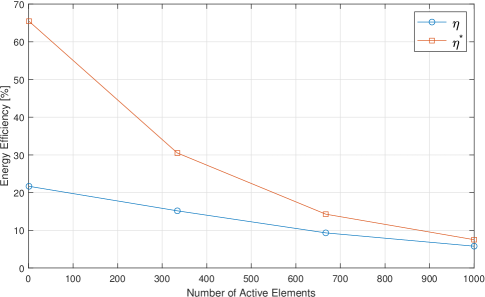
Incorporating (22) and (29), we can deduce the optimal energy efficiency for the proposed system. Comparing this efficiency with the baseline outlined in (20), Fig. 4 illustrates the energy efficiency in relation to the number of active elements for both the baseline and the optimized scenarios. The comparison underscores that the optimal () delivers a markedly better energy efficiency than its baseline counterpart, underlining the potency of our advocated technique.
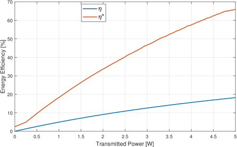
In practical wireless communication systems, transmitters dynamically adjust their power output in response to various factors, including environmental conditions and channel states. Such modifications can significantly influence the system’s energy efficiency, underscoring the importance of comprehending its implications. Fig. 5 illustrates the relationship between transmitted power (denoted as ) and energy efficiency within the proposed systems. For analytical purposes, two scenarios are presented: a baseline model devoid of optimization techniques and an enhanced method, , which implements the proposed optimization strategy to augment energy efficiency. Energy efficiency is measured at different transmitted power levels, showing how affects energy efficiency in both scenarios. The discernible disparities between the curves underscore the benefits of integrating optimization techniques, showcasing superior energy efficiency across different transmitted power levels in the optimized method compared to the baseline.
V Maximize considering non-ideal condition
In the complex realm of wireless communication systems, path loss significantly influences performance, particularly in suboptimal environmental conditions. Path loss inherently encompasses deterministic factors, such as distance and environmental attributes, as well as stochastic components, primarily arising from shadowing effects denoted by Considering this variability, instead of aiming for the highest possible energy efficiency, the goal becomes maximizing its average value as follows:
| (30) |
In the equation provided, signifies the expected value, which is a function of and a random variable. The path-loss, in a linear scale . To achieve (30), which includes both direct LOS signals and those reflected by RISs, we utilize the Adam optimization algorithm. This method is adept at managing intricate optimization challenges, rendering it appropriate for our system. Our system integrates various elements, from direct signals and RIS-reflected signals to phase alterations and shadowing phenomena. A notable characteristic of the Adam method is its adaptive learning rates. These rates adjust based on historical gradient data [30]. This flexibility provides stability against unpredictable variations introduced by shadowing , ensuring consistent convergence of the algorithm. Moreover, the momentum feature of Adam aids in navigating challenges in the optimization landscape, such as local extremes or unstable points, particularly those arising from interactions between direct and RIS-reflected signals. The RIS’s capability to alter phase is central to our system and benefits from the adaptability of Adam, ensuring optimal phase values within predefined limits. In light of these advantages, the Adam algorithm maintains computational efficiency even as our system expands to include multiple RISs, each with numerous reflecting elements. This underscores its role as a reliable tool for enhancing the energy efficiency of our system.
To optimize the system using the Adam algorithm, the process commences with the random initialization of phase shifts, , for each RIS element, ensuring they are constrained within the range [0, 2π]. This represents our starting point in the optimization landscape. Following this, two moment estimators, and are initialized to zero. These estimators are instrumental in adaptively adjusting the learning rates for each specific parameter, . During the optimization, we track the progress using a time step, denoted as””, which starts at zero and increments with each iteration. To prevent division by zero in our calculations, we introduce a small constant value, , ensuring stability and accuracy throughout the computational process. The core of the optimization relies on the estimation of the gradient, which is expressed as:
| (31) |
where .
The gradient of with respect to indicates the necessary direction and magnitude of adjustment to optimize the expected energy efficiency. Direct computation of this gradient can be challenging due to the evaluation of expectations over the random variable embedded in . Such evaluations might require the resolution of complex integrals or summations, especially when the system model encompasses multiple stochastic elements. To circumvent these intricacies and to encapsulate the effects of the stochastic variable , the Monte Carlo sampling technique is employed. This method facilitates the approximation of the gradient by generating numerous samples of from its established distribution. The equation for the Monte Carlo approximation of the gradient is given by:
| (32) |
Here, is the number of Monte Carlo samples generated from the distribution of , and is the samples of . The approximation method outlined in (32) provides a feasible strategy to estimate intricate expectations influenced by stochastic variables. As the sample size increases, this method tends to converge towards the true value, striking a balance between computational efficiency and statistical precision. In essence, it harmonizes the trade-off between precision and feasibility. Utilizing this approximation, the update rule for the phase shift can be formulated as
| (33) |
where is the learning rate.
To improve the optimization procedure, the Adam algorithm employs moment estimates for adaptive adjustment of the learning rates. The initial moment estimate, often termed the momentum term, is given by:
| (34) |
The subsequent moment estimate, often equated to the Root Mean Square Propagation (RMSP) term, serves as a dynamic adjuster for the learning rate. This dynamic adjustment enhances the algorithm’s stability in the face of gradient variations. Formally, the RMSP term is expressed as:
| (35) |
where and denote the exponential decay rates for the first and second moment estimates, respectively, and they are typically close to one, serves as an adaptive normalization factor, adjusting the learning rate for each parameter
The values and correspond to the first moment (mean) and the second moment (uncentered variance) of the gradients, respectively. When initialized at zero, these estimates can be biased towards zero, especially during the initial iterations. Such bias can hinder the optimization process, especially at its commencement. To counteract this bias, the Adam algorithm introduces bias-corrected versions of and . The corrected estimates are computed as:
| (36) |
Utilizing these bias-corrected values, the update formula for the phase shift is defined as:
| (37) |
With the inclusion of the bias-corrected estimates, the update rule for the phase shift is
| (38) |
The updated phase shifts, after each iteration, are subjected to a clipping procedure to ensure they remain within the permissible range. Mathematically, this can be represented as:
| (39) |
The function guarantees that remains within the defined interval maintaining the physical validity of the model. Once all the optimal individual phase shifts are obtained, they are combined into a unified variable, represented as . It is formulated as:
| (40) |
The vector acts as a consolidated representation of the optimal phase shifts throughout the system. Utilizing this vector simplifies the process of comparing energy efficiencies among different RISs. The selection of the most efficient RIS is based on the subsequent criteria:
| (41) |
This methodology facilitates the optimization of phase shifts for individual RISs and simultaneously identifies the RIS that delivers the highest energy efficiency. The step-by-step process of applying (30)-(41) is illustrated in algorithm-1.
The graphical representation in Fig. 6 depicts how the learning rate, , evolves during the optimization process using the Adam algorithm. The x-axis, labeled "Iteration", counts the number of updates made to the aiming to enhance energy efficiency. The y-axis, titled , shows the adjusted learning rate at each step. Initially, the learning rate is set higher, enabling the algorithm to swiftly explore the solution space and make significant changes to . As the process continues, the learning rate gradually decreases, allowing for more precise, smaller adjustments to . Such modulation ensures that the algorithm zeroes in on the optimal solution without undue fluctuations or overshooting. The declining trend of the learning rate is a characteristic feature of the Adam algorithm. It ensures that, at the outset, the algorithm explores solutions rapidly. However, as it nears the optimal solution, it adopts a more cautious approach, ensuring a steady and reliable convergence.
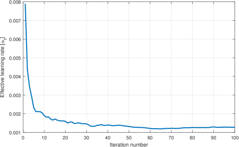
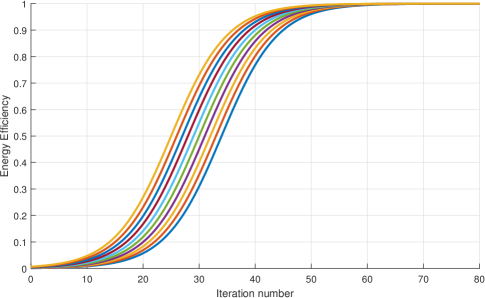
Figure 7 illustrates the progression of energy efficiency over iterative optimization using the Adam algorithm, considering various initial phase shift setups for the RISs. Each trajectory in the plot represents a distinct initial configuration of phase shifts, , for the RIS elements. The y-axis quantifies the energy efficiency, while the x-axis, labeled "Iteration", indicates the number of applications of the Adam algorithm to refine and update the phase shifts, , with the objective of optimizing energy efficiency. A close examination of Fig. 7 reveals that, irrespective of the initial configurations, all trajectories converge to a similar energy efficiency value. This behaviour underscores the robustness of the Adam optimization algorithm, which dynamically adjusts its learning rates based on the gradient’s first and second moment estimates. The algorithm’s adaptability ensures that even in the presence of stochastic variables like shadowing effect, it can navigate the optimization landscape effectively and converge to an optimal or near-optimal solution. The convergence of all trajectories to a similar value also suggests that the system’s energy efficiency has a global optimum that is reachable from various initial configurations. This is a promising observation, indicating that the system’s performance is not overly sensitive to initial conditions, and the optimization process is effective in enhancing energy efficiency across different scenarios.
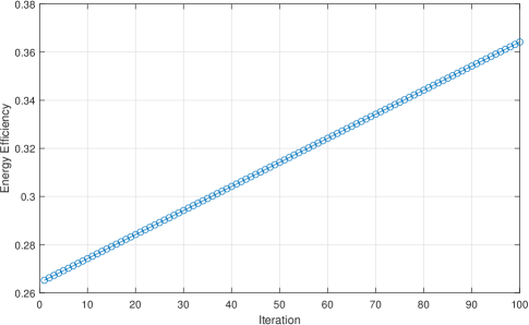
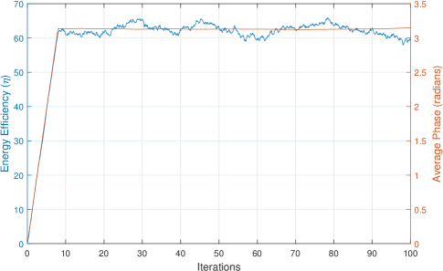
To provide a clearer understanding of the optimization process and its impact on system performance, we turn our attention to Fig. 8. This figure visually depicts the evolution of energy efficiency across iterations. The plotted line’s rising and subsequent stabilizing pattern suggests that the algorithm is effectively refining the phase shifts, leading towards an optimal or near-optimal solution. This behavior underscores the algorithm’s capability to navigate the solution space and make beneficial adjustments, ultimately achieving a desirable energy efficiency outcome.
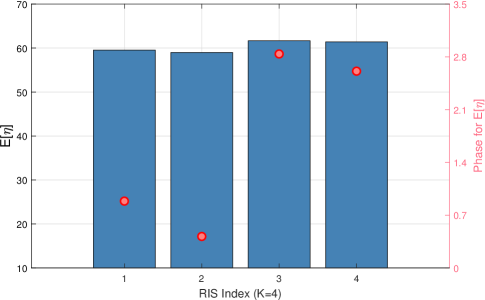
To elucidate the modulation of phase configurations of RIS elements by the Adam algorithm for the maximization of energy efficiency, Fig. 9 presents a dynamic illustration of the optimization process over time. In this figure, the curve representing energy efficiency initially ascends and subsequently stabilizes. This pattern indicates that the algorithm is progressively optimizing the phase configurations to enhance energy efficiency, eventually converging to an optimal or near-optimal solution. In parallel, the phase curve provides insights into the average adjustments made to the RIS elements over time. Notably, this curve reflects the trend of the energy efficiency curve, highlighting that the algorithm persistently modifies the configurations until a stable phase setting is achieved. While Fig. 9 unveils the dynamics of the optimization process, Fig. 10 delineates the final outcomes, detailing the maximal energy efficiency realized by each RIS at specific phase values. This figure integrates a bar chart that exhibits the maximal for every RIS, calculated from normalized phase values. The height of each bar corresponds to the energy efficiency attained by an individual RIS subsequent to phase optimization. Superimposed on this bar chart is a line graph with markers, each of which denotes the optimal phase shift at which the associated RIS reaches its peak energy efficiency. Annotations on both the bars and markers provide exact values, facilitating a comprehensive understanding of the results.
VI Conclusion
This study presents two innovative approaches designed to enhance energy efficiency in satellite-to-ground communication systems, utilizing multiple Reflective Intelligent Surfaces (RISs). The central objective of these methods is to maxmize the overall energy efficiency of the system, and this is achieved by tacking two distinct challenges. In the first approach, denoted as IE, the emphasis is on amplifying power reception by fine-tuning the phase shift of each RIS. Subsequently, Selective Diversity is used to identify the RIS delivering the maximum power. The next challenge revolves around minimizing power consumption. This challenge is articulated as a binary linear programming problem and tackled using the BPSO technique. The IE approach presumes an ideal environment where signals propagate without any path loss. This ideal scenario is used as a foundational reference for theoretical evaluations, shedding light on the peak capabilities of the system. In contrast, the second approach, termed NIE, is designed for scenarios where signal transmission is subject to path loss. Within this framework, the Adam algorithm is utilized to optimize energy efficiency. This non-ideal setting offers a pragmatic evaluation of the system’s capabilities under conventional operational conditions. The efficacy of the proposed framework is assessed under these two paradigms. Both scenarios underscore the potential energy savings of the satellite-RIS system. The ideal setting elucidates the system’s pinnacle performance under optimal conditions, while the real-world scenario underscores the practical challenges and requisite adaptations. Importantly, the framework integrates probabilistic considerations to accommodate external environmental variables, representing a substantial advancement in optimizing energy efficiency for RIS-augmented satellite communication.
References
- [1] S. Basharat, S. A. Hassan, H. Pervaiz, A. Mahmood, Z. Ding, and M. Gidlund, “Reconfigurable intelligent surfaces: Potentials, applications, and challenges for 6g wireless networks,” IEEE Wireless Communications, vol. 28, no. 6, pp. 184–191, 2021.
- [2] M. Di Renzo, A. Zappone, M. Debbah, M.-S. Alouini, C. Yuen, J. de Rosny, and S. Tretyakov, “Smart radio environments empowered by reconfigurable intelligent surfaces: How it works, state of research, and the road ahead,” IEEE Journal on Selected Areas in Communications, vol. 38, no. 11, pp. 2450–2525, 2020.
- [3] E. Basar, M. Di Renzo, J. De Rosny, M. Debbah, M.-S. Alouini, and R. Zhang, “Wireless communications through reconfigurable intelligent surfaces,” IEEE Access, vol. 7, pp. 116 753–116 773, 2019.
- [4] M. I. Khalil, “Enhancing active reconfigurable intelligent surface,” Intelligent and Converged Networks, vol. 3, no. 4, pp. 351–363, 2022.
- [5] Q. Wu and R. Zhang, “Intelligent reflecting surface enhanced wireless network via joint active and passive beamforming,” IEEE Transactions on Wireless Communications, vol. 18, no. 11, pp. 5394–5409, 2019.
- [6] Y.-C. Liang, R. Long, Q. Zhang, J. Chen, H. V. Cheng, and H. Guo, “Large intelligent surface/antennas (lisa): Making reflective radios smart,” Journal of Communications and Information Networks, vol. 4, no. 2, pp. 40–50, 2019.
- [7] L. Yang, F. Meng, J. Zhang, M. O. Hasna, and M. D. Renzo, “On the performance of ris-assisted dual-hop uav communication systems,” IEEE Transactions on Vehicular Technology, vol. 69, no. 9, pp. 10 385–10 390, 2020.
- [8] L. Yang, X. Yan, D. B. da Costa, T. A. Tsiftsis, H.-C. Yang, and M.-S. Alouini, “Indoor mixed dual-hop vlc/rf systems through reconfigurable intelligent surfaces,” IEEE Wireless Communications Letters, vol. 9, no. 11, pp. 1995–1999, 2020.
- [9] L. Yang, J. Yang, W. Xie, M. O. Hasna, T. Tsiftsis, and M. D. Renzo, “Secrecy performance analysis of ris-aided wireless communication systems,” IEEE Transactions on Vehicular Technology, vol. 69, no. 10, pp. 12 296–12 300, 2020.
- [10] L. Yang, F. Meng, Q. Wu, D. B. da Costa, and M.-S. Alouini, “Accurate closed-form approximations to channel distributions of ris-aided wireless systems,” IEEE Wireless Communications Letters, vol. 9, no. 11, pp. 1985–1989, 2020.
- [11] R. C. Ferreira, M. S. P. Facina, F. A. P. De Figueiredo, G. Fraidenraich, and E. R. De Lima, “Bit error probability for large intelligent surfaces under double-nakagami fading channels,” IEEE Open Journal of the Communications Society, vol. 1, pp. 750–759, 2020.
- [12] W. Mei and R. Zhang, “Cooperative beam routing for multi-irs aided communication,” IEEE Wireless Communications Letters, vol. 10, no. 2, pp. 426–430, 2021.
- [13] Z. Yang, M. Chen, W. Saad, W. Xu, M. Shikh-Bahaei, H. V. Poor, and S. Cui, “Energy-efficient wireless communications with distributed reconfigurable intelligent surfaces,” IEEE Transactions on Wireless Communications, vol. 21, no. 1, pp. 665–679, 2022.
- [14] G. C. Alexandropoulos, S. Samarakoon, M. Bennis, and M. Debbah, “Phase configuration learning in wireless networks with multiple reconfigurable intelligent surfaces,” in 2020 IEEE Globecom Workshops (GC Wkshps, 2020, pp. 1–6.
- [15] J. Lyu and R. Zhang, “Spatial throughput characterization for intelligent reflecting surface aided multiuser system,” IEEE Wireless Communications Letters, vol. 9, no. 6, pp. 834–838, 2020.
- [16] R. Kumar Hindustani, D. Dixit, and S. Sharma, “Outage probability analysis of multiple intelligent reflecting surface-assisted single-input single-output system with switched diversity,” International Journal of Communication Systems, vol. 36, no. 14, p. e5550, 2023. [Online]. Available: https://onlinelibrary.wiley.com/doi/abs/10.1002/dac.5550
- [17] P. Wang, J. Fang, X. Yuan, Z. Chen, and H. Li, “Intelligent reflecting surface-assisted millimeter wave communications: Joint active and passive precoding design,” IEEE Transactions on Vehicular Technology, vol. 69, no. 12, pp. 14 960–14 973, 2020.
- [18] B. Zheng, C. You, and R. Zhang, “Double-irs assisted multi-user mimo: Cooperative passive beamforming design,” IEEE Transactions on Wireless Communications, vol. 20, no. 7, pp. 4513–4526, 2021.
- [19] C. Huang, Z. Yang, G. C. Alexandropoulos, K. Xiong, L. Wei, C. Yuen, Z. Zhang, and M. Debbah, “Multi-hop ris-empowered terahertz communications: A drl-based hybrid beamforming design,” IEEE Journal on Selected Areas in Communications, vol. 39, no. 6, pp. 1663–1677, 2021.
- [20] W. Ni, X. Liu, Y. Liu, H. Tian, and Y. Chen, “Resource allocation for multi-cell irs-aided noma networks,” IEEE Transactions on Wireless Communications, vol. 20, no. 7, pp. 4253–4268, 2021.
- [21] M. A. Saeidi, M. J. Emadi, H. Masoumi, M. R. Mili, D. W. K. Ng, and I. Krikidis, “Weighted sum-rate maximization for multi-irs-assisted full-duplex systems with hardware impairments,” IEEE Transactions on Cognitive Communications and Networking, vol. 7, no. 2, pp. 466–481, 2021.
- [22] L. Bariah, L. Mohjazi, H. Abumarshoud, B. Selim, S. Muhaidat, M. Tatipamula, M. A. Imran, and H. Haas, “Ris-assisted space-air-ground integrated networks: New horizons for flexible access and connectivity,” IEEE Network, pp. 1–8, 2022.
- [23] M. Aldababsa, A. M. Salhab, A. A. Nasir, M. H. Samuh, and D. B. da Costa, “Multiple riss-aided networks: Performance analysis and optimization,” IEEE Transactions on Vehicular Technology, vol. 72, no. 6, pp. 7545–7559, 2023.
- [24] H. Niu, Z. Lin, K. An, X. Liang, Y. Hu, D. Li, and G. Zheng, “Active ris-assisted secure transmission for cognitive satellite terrestrial networks,” IEEE Transactions on Vehicular Technology, vol. 72, no. 2, pp. 2609–2614, 2023.
- [25] Z. Lin, H. Niu, K. An, Y. Wang, G. Zheng, S. Chatzinotas, and Y. Hu, “Refracting ris-aided hybrid satellite-terrestrial relay networks: Joint beamforming design and optimization,” IEEE Transactions on Aerospace and Electronic Systems, vol. 58, no. 4, pp. 3717–3724, 2022.
- [26] M. Najafi, V. Jamali, R. Schober, and H. V. Poor, “Physics-based modeling and scalable optimization of large intelligent reflecting surfaces,” IEEE Transactions on Communications, vol. 69, no. 4, pp. 2673–2691, 2021.
- [27] O. Kodheli, E. Lagunas, N. Maturo, S. K. Sharma, B. Shankar, J. F. M. Montoya, J. C. M. Duncan, D. Spano, S. Chatzinotas, S. Kisseleff, J. Querol, L. Lei, T. X. Vu, and G. Goussetis, “Satellite communications in the new space era: A survey and future challenges,” IEEE Communications Surveys and Tutorials, vol. 23, no. 1, pp. 70–109, 2021.
- [28] J. C. Whitaker, The electronics handbook, 2nd ed., ser. The Electrical engineering handbook series. Boca Raton, Fla: CRC Press, 2005.
- [29] W. Tang, M. Z. Chen, X. Chen, J. Y. Dai, Y. Han, M. Di Renzo, Y. Zeng, S. Jin, Q. Cheng, and T. J. Cui, “Wireless communications with reconfigurable intelligent surface: Path loss modeling and experimental measurement,” IEEE Transactions on Wireless Communications, vol. 20, no. 1, pp. 421–439, 2021.
- [30] D. P. Kingma and J. Ba, “Adam: A method for stochastic optimization,” 2017.
- [31] D. Vallado and W. McClain, Fundamentals of Astrodynamics and Applications, ser. Fundamentals of Astrodynamics and Applications. Microcosm Press, 2001.
- [32] ITU-R, “Propagation data required for the evaluation of interference between stations in space and those on the surface of the earth,” International Telecommunication Union (ITU), P Series ITU-R P.619-5, 2021.
- [33] L. Cervante, B. Xue, M. Zhang, and L. Shang, “Binary particle swarm optimisation for feature selection: A filter based approach,” in 2012 IEEE Congress on Evolutionary Computation, 2012, pp. 1–8.