Semianalytically Designed Dual Polarized Printed-Circuit-Board (PCB) Metagratings
Abstract
Metagratings (MGs), sparse (periodic) composites of subwavelength polarizable particles (meta-atoms), have demonstrated highly efficient diffraction engineering capabilities via meticulous tailoring of the interaction between individual scatterers. To date, MGs at microwave frequencies have mostly been devised for either transverse electric (TE) or transverse magnetic (TM) polarized scenarios, which limits their use in many practical applications. Herein, we bridge this gap and present a comprehensive semianalytical design method for dual-polarized MGs with a separable response for TE and TM waves. First, by relating a printed circuit board (PCB) compatible array of dog-bone elements with the canonical dipole line analytical model, we establish a meta-atom for TM-polarized MGs, featuring negligible interaction with TE waves. Subsequently, we integrate the proposed configuration with a systematic synthesis scheme to implement a TM beam splitter MG, harnessing the equivalent dipole line model to resolve analytically the optimal meta-atom coordinates and dog-bone polarizability, without resorting to full-wave optimization. Finally, we show that a dual-polarized MG beam splitter can be conveniently synthesized correspondingly, combining the TM-polarized structure as is with previously reported TE-polarized MG designs. This work paves a clear path towards integration of sparse, semianlaytically synthesized, efficient MGs in practical dual-polarized communication and imaging applications.
Index Terms:
Metagrating, beam splitter, dual polarization, dipole lineI Introduction
In recent years, the emergence of semianalytical design tools for electromagnetic composites have enabled the creation of new advanced devices unavailable before. In such configurations, where the structure consists of many degrees of freedom (DOF), beyond the capability of the conventional full-wave optimizers, analytically-based models can be employed to reduce the computation time and yet reach near-optimal performance. In the realm of metasurfaces, these ideas manifest themselves in the macroscopic design scheme [1, 2, 3, 4, 5, 6]. Metasurfaces, dense planar arrangements of subwavelength polarizable particles termed meta-atoms (MAs), are typically designed in two separate steps: first, the macroscopic design step, where a continuously varying surface with a different surface impedance in each location is manifested to reach a desired functionality; second, the microscopic design step, where a batch of MAs is designed in various methods, matching a suitable physical structure to every local response prescribed by the former step. Transmissive beam deflectors[7, 8, 9, 10, 11, 12, 13, 14], flat lenses[15, 16, 17], and metasurface-based antennas[18, 19, 20], all rely on analytical macroscopic design techniques, are only some examples to devices that have demonstrated unprecedented efficacy by utilizing the aforementioned combined synthesis schemes.
Nonetheless, the microscopic design step described above poses certain difficulties. First, it requires the implementation of many, densely-arranged, often geometrically complex, MAs. This could lead to significant fabrication and design challenges, and tends to involve time-consuming full-wave optimizations [21, 18, 22, 23, 24]. Indeed, some simplifications can be achieved by considering cascaded impedance sheet models, utilized to devise Huygens’ and bianisotropic meta-atoms[11, 21, 13]. Yet, these techniques still lack crucial aspects, neglecting interlayer near-field interactions and often ignoring conductor loss; consequently, final optimization in full-wave solvers is almost always necessary. Second, metasurface design procedures rely on the assumption that when the separately designed MAs are combined together, the abstract continuous response prescribed by the macroscopic design would be reproduced (the homogenization approximation). This assumption, however, is hard to justify rigorously, especially for general metasurfaces with highly-inhomogeneous polarizability distributions, since the intercoupling between different neighboring MAs is typically not considered in the microscopic design scheme. Furthermore, it is not a priori clear how to determine the discretization resolution (meta-atom size) that would guarantee successful emulation of the homogenized response [25]. Therefore, relying on these approaches may make it difficult to identify the root cause of discrepancies between theoretical predictions and the ultimate metasurface performance, when such are observed.
One of the developments that was motivated by these microscopic design challenges when applied to practical complex media devices was the concept of metagratings (MGs). These sparse (typically periodic) arrangements of subwavelength polarizable particles (MAs) [26] have shown great potential in producing novel high efficiency beam-manipulating devices [27, 28, 29, 30]. In contrast to metasurfaces, MGs are devised by considering the interactions and mutual coupling between the MAs using reliable analytical models [29, 31]. These models, enabling delicate tunning of the interference patterns formed by the MGs upon external excitation, faciliated a large number of devices demonstrating a variety of wavefront manipulation functionalities [26]. Indeed, MGs were utilized across the electromagnetic spectrum to realize perfect anomalous reflection [29, 30], refraction [27, 32, 33], and focusing devices [34, 35].
In particular, in recent years, we have developed and utilized such a suitable analytical model to realize printed circuit board (PCB) MGs that perform versatile diffraction engineering tasks at microwave frequencies, devising the complete fabrication-ready layout without time consuming full-wave optimizations [31, 36, 37, 38]. Alas, as the model and subsequently the resultant MGs rely on elongated loaded wires as the underlying MAs[31, 1], this design scheme can only accommodate transverse electric (TE) polarized functionalities. Despite this alleged limitation, this convenient configuration and theoretical framework were further harnessed and elaborated by various groups to tackle a broad range of applications and scenarios, making it one of the more common embodiments for MGs at microwave frequencies to date [39, 40, 41, 42, 38, 43, 44, 45, 46, 47, 48].
Indeed, some researchers have suggested to address transverse magnetic (TM) polarized waves via MGs using vertical conducting loops [49], in which induced currents emulate a magnetic line source response, or by using grooves in metallic slabs[50, 51, 52, 53, 54], which support propagating TM modes. However, these solutions are not compatible with low-profile PCB technology, and may lead to challenging assembly and bulky devices. Another alternative considered for TM-polarized MGs is to utilize wide strip arrays (essnetially, narrow slot arrays), which interact with the orthogonal polarization following Babinet’s principle [55, 56, 28, 57, 58]. Nonetheless, these strips also interact with TE polarized waves, making it more difficult to design a device with different responses to the two orthogonal polarizations.
In this paper, we propose an alternative solution, developing a comprehensive semianalytical design scheme for dual-polarized PCB compatible MGs. Specifically, we propose to utilize properly aligned dog-bone arrays as MAs [59], which are susceptible to TM-polarized fields while exhibiting negligible response to TE-polarized excitations (Fig. 1). As shown, since the electric dipoles induced on this meta-atom configuration fit the canonical dipole line model [60], MG analysis and synthesis schemes can be conveniently augmented to analytically accommodate this new geometry [61]. Importantly, as the resultant TM-type MG does not interact with TE-polarized fields, it can be readily combined with the standard loaded-wire embodiment of TE-polarized MGs [38] to create separable-response, dual-polarized, PCB MGs.
We demonstrate our approach by designing a highly-efficient wide-angle polarization-dependent beam-splitter, combining independently devised TE- and TM- susceptible configurations to impose different splitting angles for each polarization. Contrary to metasurfaces previously developed to implement similar functionalities, incorporating dual-polarized control via dense Jerusalem crosses or crossed-dipole meta-atoms [62, 63, 64], the proposed MG-based devices are shown to offer a significant complexity reduction, featuring a sparse final layout and simplified design process. As verified via full-wave simulations, the formulated systematic semianalytical methodology, supported by a rigorous analytical model while yielding detailed design specifications, forms a reliable tool for the development of novel dual-polarized MG-based devices. In particular, such a design scheme can be highly appealing for applications such as satellite communication systems [65, 66] and future cellular networks [67, 68].
II Theory
II-A Formulation
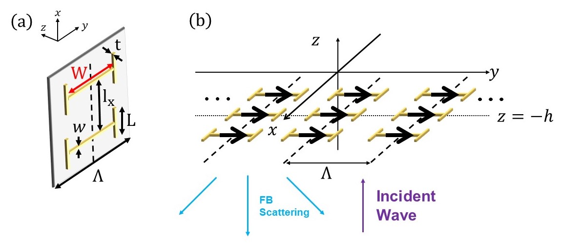
We consider first the structure depicted in Fig. 1, where columns of dog-bone elements are positioned on , parallel to the plane, surrounded by a homogeneous medium with permittivity and permeability . Harmonic time dependency is assumed and suppressed, defining the wave number , the wavelength , and the operating frequency ; the wave impedance is . The printed dog-bone elements have a trace width of and thickness . They are closely spaced along the axis in an -periodic arrangement, while positioned in a sparse -periodic formation along . The structure is excited by a TM-polarized plane wave () incoming from below; once impinging upon the dog-bone elements, it induces electric dipoles directed parallel to the axis111While the induced current profile may be more involved [69], we assume sufficiently small dog-bones such that the leading (electric dipole) term in the multipole expansion is sufficient to obtain an accurate description of the scattering phenomena., effectively forming a dipole line (secondary) source [60]. As , we view the th dipole line as a continuous entity (MA) described by an average current density , related to the dipole moment per unit length of the dog-bones via , where is the position of the th dipole line.
Correspondingly, for given induced dipole moments, the secondary fields generated by these TM MAs in the described periodic arrangement would follow the solution of the canonical dipole line problem [60, 70], reading
| (1) | ||||
where is the th order Hankel function of the second kind, stands for the observation point, and is the location of the th MA. We utilize the Poisson summation formula to find the Floquet-Bloch (FB) representation of the scattered fields in our case[1]. The tangential fields generated by the TM MGs would therefore read
| (2) | ||||
with and () being the th mode transverse and longitudinal wavenumbers, respectively. As expected, the tangential magnetic field changes sign when crossing the electric current source sheet [71], manifesting the fact that the scattered waves travel away from the MG.
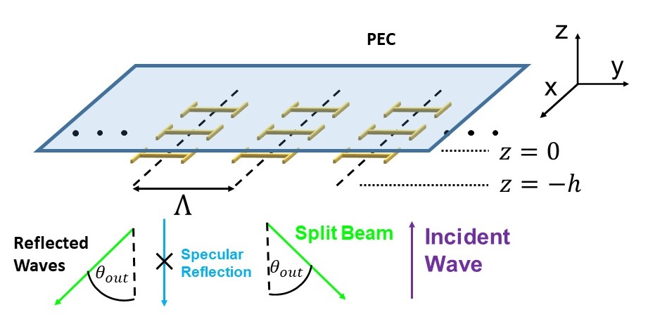
Once we have obtained a formulation for the fields scattered off an isolated TM MG, we may proceed and utilize it for deriving analytical expressions for the scattered fields when the MG is embedded in a more involved configuration. In particular, we are interested herein in devising a TM beam splitter, operating in reflect mode. To this end, we consider the scenario described in Fig. 2, where the MG is positioned a distance below a perfect-electric-conductor (PEC) mirror. Similar to previous work [31, 29], to analyze the scattered fields in this scenario we evaluate separately the contributions associated with the external fields (in the absence of the MG), and the secondary fields stemming from the induced dipoles.
The external fields consist of a normally incident plane wave approaching from and its specular reflection from the PEC at , namely,
| (3) |
The contribution of the secondary fields generated by the (induced) dipole line MG in the presence of the reflecting PEC can be calculated by using (2) in conjunction with image theory. In the observation region () below the MG, these are given by
| (4) | ||||
The total field will thus be the summation of these two field contributions, namely,
| (5) |
The magnetic field can be subsequently deduced via Maxwell’s equations by a simple derivation, yielding, together with (3)-(5), explicit expressions for the electric and magnetic tangential fields below the MG (),
| (6) | ||||
By considering these total fields scattered from the overall MG configuration (dog-bone array + PEC), we may now formulate constraints on the various mode amplitudes (coupling coefficients) as to obtain the goal functionality - perfect beam splitting towards . In analogy to the TE-polarized case [31], our degrees of freedom in the design would be the period size ; the MA dimensions [specifically, the dog-bone arm length , cf. Fig. 1(a)], related to their polarizability; and the distance between the MG and the PEC reflector.
II-B Perfect beam splitting
To synthesize the desired TM beam splitter, we follow the methodology presented in [31, 29], and impose three physical demands on the realized structure. First, we require that all higher-order FB modes () would be evanescent, such that real power could only be scattered towards the specular direction (which is always allowed) and to the desired split angles (). Correspondingly, according to the FB theorem[72], we tune the MG periodicity such that the trajectory of the first FB mode would coincide with for a normally incident wave, and demand that all other modes have decaying wave functions. Formally, this translates into
| (7) | |||||
This resolves the first degree of freedom, relating the periodicity to the output angle while identifying the valid angular range.
Second, we demand that no power will be coupled to the specular reflection () mode. This is accomplished by requiring that the field scattered by the MG to this direction would destructively interfere with the contribution of the external fields. Reviewing (6) and stipulating that the mode amplitude would vanish results in yet another condition
| (8) |
which indicates the induced dipole strength required for countering the specular reflection of the incident fields.
Lastly, since we wish the designed MG to allow realization via passive and lossless (reactive) components, we demand that power will be overall conserved by the system. Specifically, we require the net real power crossing any given plane below the MG would vanish, namely
| (9) |
Substituting (6), (8) into (9) yields, after some algebraic simplifications, the following nonlinear equation
| (10) |
the resolution of which identifies the possible dog-bone-PEC spacings that would enable realization of passive and lossless MG for perfect beam splitting towards .
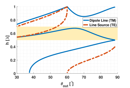
Figure 3 presents the relation between these distances and the output angle , obtained by graphically solving222Since (10) is nonlinear, several solution branches exist in Fig. 3. (10); for comparison, the analogous relation corresponding to the TE MG beam splitter presented in [31], based on capacitively loaded wires, is shown as well. Examining the nonlinear equation applicable for the TE-polarized case [Eq. (14) of [31]] with respect to (10), one can pinpoint the difference between the two trends as stemming from the different wave impedances associated with TE- and TM-polarized waves [71]. We further note that (10) is consistent with the results presented in [57] for a TM MG based on wide metallic strips as meta-atoms. Nonetheless, as will be shown in Section III, the MG realization proposed herein for TM-polarized applications is advantageous since it does not interact with TE-polarized waves, while at the same time enabling convenient assessment of the MA geometry.
II-C Meta-atom polarizability
Once the position of the MG below the PEC mirror is set via (10), we proceed to finding the suitable MA polarizability of the dog-bones to be placed there, guaranteeing implementation of the perfect beam splitting. Instead of the loaded wires utilized before for realizing TE-polarized MG [31] that could sustain a continuous current along them, the interaction with the elementary scatterers used herein are more appropriately described via induced (-directed) dipole moments [Fig. 1(b)]. Correspondingly, the relation between the local field applied at the dog-bone position to the excited dipole moment is given by the scatterer polarizability [1]
| (11) |
where stands for the local field at the dipole location, created by all the sources in the given geometry but the one under test, and corresponds to the MA polarizability per unit length. We should emphasize that the relation that ties the induced current and the acting fields used herein differs from the one employed in [31] in the sense that the acting fields herein exclude the fields generated by the induced dipole moment itself, in consistency with the polarizability concept [59, 1, 73, 57].
Considering the geometry in Fig. 2, the local field at the vicinity of the reference MA at is composed of three field contributions
| (12) | ||||
where is the external field defined in (3), is the intralayer field created by the other induced dipoles residing on the MG plane, and stands for the contribution of the image sources corresponding to the latter, formed by the reflecting PEC at . Overall, utilizing (1)-(3), the local field can be explicitly formulated as
| (13) | ||||
where the intralayer coupling is calculated directly from (1). Noting that for large distances , attenuates rather quickly [74], we find that the second term in (13) readily converges as a sum of non-radiative waves (reactive near fields). Obeserving that the FB series in the third term includes only a finite number of propagating harmonics (the rest are rapidly decaying evanescent components), provides the necessary guarantee that the entire RHS of (13) properly converges.
By substituting (8), (13) back to the definition (11), we find that the MA polarizability required for realizing perfect beam splitting of a normally incident TM-polarized wave towards is
| (14) | |||
This concludes the principal design procedure for the proposed TM-polarized MG. For given operating frequency and split angle , we first use (10) to extract the PEC-MG separation required to guarantee complete suppression of the specular reflection via a passive and lossless MG (if proper dipoles are induced on the MAs by the impinging fields). Next, the extracted is substituted into (14) to resolve the dipole line polarizability per unit length that would ensure that the desired dipole moment would indeed be induced. With these in hand, the overall synthesis of the MG can be completed by setting the MA dimensions to realize the evaluated , which will be addressed and demonstrated in next section.
III Results and discussion
III-A TM-polarized MG beam splitter
To verify and demonstrate the theory developed in Section II, we utilize it to devise a TM-polarized beam splitter at 20 GHz. In particular, we aim at devising a set of beam splitters for various prescribed split angles, covering the range between and [complying with (7)]. Our first step would be to match a suitable MA geometry to fulfill our requirement for the MA polarizability (see Section II-C). To this end, we establish a method to evaluate the polarizabilty of a given scatterer geometry, following the procedure proposed in [75, 49].
As described in Section II-A, we focus on dog-bone arrays as meta-atoms for the TM-polarized device (Fig. 1), with their trace width and thickness fixed to m and m, respectively, following standard fabrication capabilities. We set their side-arm length to , acting as a constant inductive load, while using the dipole length to tune the meta-atom response (modify the working point around the resonance). Correspondingly, we consider a range of values for , serving as the degree of freedom for realizing the desired polarizability values found as per (14). Subsequently, to characterize the TM MG polarizability corresponding to a given , we place the MA in a -periodic formation in a full-wave solver (CST Microwave Studio), excite it with a normally incident plane wave [as shown in Fig. 1 (b)], and record the reflection coefficient of the fundamental mode . Since this coefficient can be readily related to the induced dipole by considering the term in (2), namely, , we can use the recorded in (11) to estimate the effective polarizability of this specific dipole line geometry, reading
| (15) |
Figure 4 presents the extracted effective polarizabilities of the TM-susceptible dog-bone MAs as a function of the dipole length, for a series of period sizes . The plots confirm that the polarizability is an inherent property of the dog-bone column alone, almost independent of the period size. The slight differences found in this regard for different values of are attributed to approximated dipole model used in our formulation leading to (15), neglecting high order multipoles associated with the dog-bone side-arms, which may affect the mutual coupling between adjacent MAs. Nonetheless, since the differences between the curves is very small, we choose to use the one corresponding to for devising the MG realizations herein and in subsequent sections.
It should be noted that the polarizability trends in Fig. 4 match the polarizability of an inductively loaded dipole (loaded wire [59, 1]), as previously reported in the literature [73]. Compared to pristine dipoles, it can be seen that the dog-bone side-arms, acting as inductive loads, shift the resonance frequencies down, which manifests itself as a shift of the polarizability graph towards smaller . Similarly, since the polarizability is proportional to the electrical length of the dipole (and not its absolute length), correspondence can be found also with the typical frequency dependency of dipole polarizability [73].

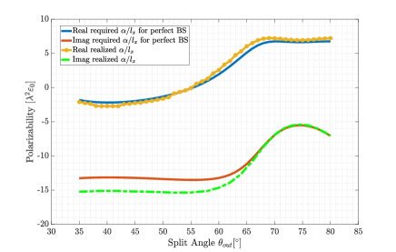
With the devised dipole lines in our hands, we continue and implement the theory as mentioned in Section II-A. Our degrees of freedom in the design would be the period size (), the dog-bone (meta-atom) arm length (), and the MG separation distance from the reflector (). For a given , we (i) use the FB theorem (7) to set the MG periodicity; (ii) enforce specular reflection elimination and power conservation by utilizing a spacing which solves (10) for the prescribed (we focus on the solution branch highlighted in Fig. 3, which covers the entire angular splitting range); and (iii) calculate the required meta-atom polarizability for the chosen using (14), translating it into the actual dog-bone dimensions by finding the closest geometry in our lookup table (Fig. 4) that provides the goal poarizability.
We follow this approach for the range of angles . The corresponding required (solid lines) are presented in Fig. 5 for each of the split angles, along the closest achievable value (by means of least square error) using the specific dog-bone geometry (dot-dashed or circle markers) as deduced from Fig. 4. As can be seen, the chosen MA geometry satisfactorily allows meeting the demands in terms of polarizability, with a slight deviation in the imaginary part for split angles below . Finally, the prescribe polarizability (Fig. 5) is translated into actual dog-bone dimensions (dipole length ) with the aid of Fig. 4, setting the last degree of freedom and thus finalizing the design. The resultant beam splitters were then defined and simulated in a full-wave solver (CST Microwave Studio), for verification. The final design parameters along with the recorded TM MG beam splitter performance are presented in Table I.
[b] Splitting Efficiency Specular reflection Losses Bandwidth
Figure 6 shows the dog-bone dipole length as a function of the desired split angle as predicted by the described synthesis method (solid blue), along with the actual values (blue circles) that yield highest beam splitting efficiency as obtained from limited parametric sweeps in CST around the predicted value. As shown by these plots, corresponding to the left axis of Fig. 6, the results match very well, indicating that our seimanalytical design method achieves a near optimal design for every split angle, without actually involving full-wave optimizations. The orange markers corresponding to the right axis of Fig. 6 verify that complete specular reflection suppression is indeed obtained for all considered angles (x markers), while the beam-splitting efficiency approaches unity (squares). These conclusions are confirmed quantitatively by the values presented in Table I.
A closer examination of Table I reveals that the fraction of power coupled to the specular reflection and the modes ( directed beams) does not sum up to unity at all points; this is due to inevitable conductor loss in the realistic copper traces realizing the dog-bone in practice, which is, however, quite minor. Similar observations has been made for TE-polarized MGs [31], where the copper traces implementing the beam splitter absorb a fraction of the power.
To further probe the fidelity of our design method, we compare in Fig. 7 the analytically predicted electric fields (6) with the fields recorded by the full-wave solver when simulating the actual dog-bone configuration specified in Table I, for a representative case (MG realizing beam splitting towards ). As can be clearly observed, the two field snapshots agree very well, except in the regions that are very close to the dog-bone construct. This can be explained by the finite size of the dog-bone element, which is not accounted for in the theoretical model, which analyzes it as an infinitesimal -directed dipole; a similar observation has been made for TE-polarized MGs [31].
These results confirm that the formulated semianalytical scheme and chosen MA realization indeed enable systematic design of TM-polarized MGs, demonstrating efficient beam manipulation with a sparse PCB-compatible design while avoiding full-wave optimization.
III-B Dual-polarized beam splitter
As discussed in Section I, one of the main advantages of the proposed PCB-compatible TM MG geometry is that it does not interact with TE-polarized fields (the dominant induced dipoles are along the axis, with a negligible polarizability component along the axis [76, 64]). Consequently, one can readily devise dual-polarized MGs with independent response to TE and TM polarized fields by combining the TM MG configuration presented herein with the TE MG configuration reported in [31] (based on loaded wires along , which interacts mostly with TE-polarized fields) on the same PCB. Since either design is practically sensitive to only a single polarization, one can simply follow separately the design schemes for the TM (this work) and TE [31] polarized MGs, and then define the two resultant copper traces together on the same board.
We demonstrate this by synthesizing a dual-polarized MG beam splitter, reflecting different polarization components into different angles. In particular, we use the scheme developed herein to design a TM beam splitter with a corresponding period size , and the one presented in [31] to design a TE beam splitter with a period size (Fig. 8). These specific split angles were chosen such that a convenient macro-period could be defined for the combined structure (containing both the TM dog-bone and the TE loaded wire MGs), with . Correspondingly, according to Fig. 3, each polarization response requires a different PEC-MG spacing, namely, and , which indicate the distance for the TE and TM polarizations, respectively. Similarly, the required dog-bone width and loaded-wire capacitor width can be found by invoking separately the methodologies outlined herein (Table I) and in [31], respectively.
Subsequently, and without any further optimization, we superimpose the two designs in CST Microwave Studio, forming a single structure with interleaved TE and TM MAs (Fig. 8). Running the full-wave solver with the resultant dual polarized MG beam splitter reveals that, as expected, independent beam splitting for the two polarizations has been achieved, with less than of the incident power coupled to undesired specular reflection. The design achieves and beam power splitting efficiency for the TE and TM incident beams respectively. The remaining power dissipates in the copper traces due to the aforementioned conductor loss. This verifies that the two MA configurations indeed do not interfere with one another, effectively separating between the TE- (deflected towards ) and TM- (deflected towards ) polarized components of the incident wave.
The electric fields within the device (Fig. 9) further confirm these conclusions, additionally indicating the good correspondence between analytical and full-wave predictions. It should be noted that the device performance was found to be insensitive to the lateral offset between the two gratings, providing further evidence to the negligible coupling between the two polarizations in the chosen MAs.
The presented results verify the successful achievement of our goal in this work: proposing a TM-susceptible MG that does not interact with TE-polarized fields, enabling seamless integration of single-polarized MGs into a dual-polarized device with a separable polarization response, without requiring any redesign or optimization.
IV Conclusion
To conclude, we have presented a detailed semianalytical approach for designing PCB compatible TM MGs, providing a holistic methodology translating user defined requirements into detailed fabrication-ready devices based on canonical dipole line and particle polarizability models. We have demonstrated successfully how this methodology can be used for implementing a reflective beam splitter, which can be designed to deflect beams towards a wide range of oblique angles with high efficacy. We have further shown that since our proposed (dog-bone based) TM-susceptible MG does not interact with TE fields, it can be utilized to realized dual-polarized MG constructs by seamlessly combining independently devised TE-susceptible (loaded-wire based) MG formations developed in previous work; a polarization-dependent beam splitter was presented based on this idea. These results, verified via full-wave simulations, are expected to lay a rigorous and convenient framework for the development of advanced dual-polarized MG-based devices, establishing a set of effective tools for meeting the requirements of practical communication systems with sparse and rapidly designed composites.
References
- [1] S. Tretyakov, Analytical Modeling in Applied Electromagnetics. Artech House, 2003.
- [2] E. F. Kuester, M. A. Mohamed, M. Piket-May, and C. L. Holloway, “Averaged transition conditions for electromagnetic fields at a metafilm,” IEEE Trans. Antennas Propag., vol. 51, no. 10, pp. 2641–2651, 2003.
- [3] C. L. Holloway, E. F. Kuester, J. A. Gordon, J. O’Hara, J. Booth, and D. R. Smith, “An overview of the theory and applications of metasurfaces: The two-dimensional equivalents of metamaterials,” IEEE Antennas Propag. Mag., vol. 54, no. 2, pp. 10–35, 2012.
- [4] A. Epstein and G. V. Eleftheriades, “Huygens’ metasurfaces via the equivalence principle: design and applications,” J. Opt. Soc. Am. B, vol. 33, no. 2, pp. A31–A50, 2016.
- [5] S. B. Glybovski, S. A. Tretyakov, P. A. Belov, Y. S. Kivshar, and C. R. Simovski, “Metasurfaces: From microwaves to visible,” Phys. Rep., vol. 634, pp. 1–72, 2016.
- [6] J. Hu, S. Bandyopadhyay, Y.-h. Liu, and L.-y. Shao, “A review on metasurface: from principle to smart metadevices,” Frontiers Phys., vol. 8, p. 586087, 2021.
- [7] P. Lalanne, S. Astilean, P. Chavel, E. Cambril, and H. Launois, “Blazed binary subwavelength gratings with efficiencies larger than those of conventional échelette gratings,” Opt. Lett., vol. 23, no. 14, pp. 1081–1083, 1998.
- [8] Z. Bomzon, G. Biener, V. Kleiner, and E. Hasman, “Space-variant pancharatnam–berry phase optical elements with computer-generated subwavelength gratings,” Opt. Lett., vol. 27, no. 13, pp. 1141–1143, 2002.
- [9] N. Yu, P. Genevet, M. A. Kats, F. Aieta, J.-P. Tetienne, F. Capasso, and Z. Gaburro, “Light propagation with phase discontinuities: generalized laws of reflection and refraction,” Science, vol. 334, no. 6054, pp. 333–337, 2011.
- [10] C. Pfeiffer and A. Grbic, “Metamaterial huygens’ surfaces: tailoring wave fronts with reflectionless sheets,” Phys. Rev. Lett., vol. 110, no. 19, p. 197401, 2013.
- [11] F. Monticone, N. M. Estakhri, and A. Alu, “Full control of nanoscale optical transmission with a composite metascreen,” Phys. Rev. Lett., vol. 110, no. 20, p. 203903, 2013.
- [12] M. Selvanayagam and G. V. Eleftheriades, “Discontinuous electromagnetic fields using orthogonal electric and magnetic currents for wavefront manipulation,” Opt. Express, vol. 3727, no. 12, pp. 3720–3727, 2013.
- [13] A. Epstein and G. V. Eleftheriades, “Arbitrary power-conserving field transformations with passive lossless omega-type bianisotropic metasurfaces,” IEEE Trans. Antennas Propag., vol. 64, no. 9, pp. 3880–3895, 2016.
- [14] V. S. Asadchy, M. Albooyeh, S. N. Tcvetkova, A. Díaz-Rubio, Y. Ra’di, and S. A. Tretyakov, “Perfect control of reflection and refraction using spatially dispersive metasurfaces,” Phys. Rev. B, vol. 94, no. 7, p. 075142, aug 2016.
- [15] Q. Yang, J. Gu, D. Wang, X. Zhang, Z. Tian, C. Ouyang, R. Singh, J. Han, and W. Zhang, “Efficient flat metasurface lens for terahertz imaging,” Opt. Express, vol. 22, no. 21, pp. 25 931–25 939, 2014.
- [16] D. Lin, P. Fan, E. Hasman, and M. L. Brongersma, “Dielectric gradient metasurface optical elements,” Science, vol. 345, no. 6194, pp. 298–302, 2014.
- [17] V. S. Asadchy, Y. Ra’di, J. Vehmas, and S. A. Tretyakov, “Functional metamirrors using bianisotropic elements,” Phys. Rev. Lett., vol. 114, no. 9, p. 095503, mar 2015.
- [18] A. Epstein, J. P. Wong, and G. V. Eleftheriades, “Cavity-excited huygens’ metasurface antennas for near-unity aperture illumination efficiency from arbitrarily large apertures,” Nature Commun., vol. 7, no. 1, pp. 1–10, 2016.
- [19] M. Faenzi, G. Minatti, D. González-Ovejero, F. Caminita, E. Martini, C. Della Giovampaola, and S. Maci, “Metasurface antennas: New models, applications and realizations,” Sci. Rep., vol. 9, no. 1, pp. 1–14, 2019.
- [20] M. Boyarsky, T. Sleasman, M. F. Imani, J. N. Gollub, and D. R. Smith, “Electronically steered metasurface antenna,” Sci. Rep., vol. 11, no. 1, pp. 1–10, 2021.
- [21] C. Pfeiffer and A. Grbic, “Bianisotropic metasurfaces for optimal polarization control: Analysis and synthesis,” Phys. Rev. Appl., vol. 2, no. 4, p. 044011, 2014.
- [22] M. A. Cole, A. Lamprianidis, I. V. Shadrivov, and D. A. Powell, “Refraction efficiency of huygens’ and bianisotropic terahertz metasurfaces,” arXiv preprint arXiv:1812.04725, 2018.
- [23] M. Chen, E. Abdo-Sánchez, A. Epstein, and G. V. Eleftheriades, “Theory, design, and experimental verification of a reflectionless bianisotropic Huygens’ metasurface for wide-angle refraction,” Phys. Rev. B, vol. 97, no. 12, p. 125433, mar 2018.
- [24] G. Lavigne, K. Achouri, V. S. Asadchy, S. A. Tretyakov, and C. Caloz, “Susceptibility derivation and experimental demonstration of refracting metasurfaces without spurious diffraction,” IEEE Trans. Antennas Propag., vol. 66, no. 3, pp. 1321–1330, 2018.
- [25] N. M. Estakhri and A. Alu, “Wave-front transformation with gradient metasurfaces,” Phys. Rev. X, vol. 6, no. 4, p. 041008, 2016.
- [26] Y. Ra’di and A. Alù, “Metagratings for efficient wavefront manipulation,” IEEE Photon. J., vol. 14, no. 1, pp. 1–13, 2021.
- [27] D. Sell, J. Yang, S. Doshay, R. Yang, and J. A. Fan, “Large-angle, multifunctional metagratings based on freeform multimode geometries,” Nano Lett., vol. 17, no. 6, pp. 3752–3757, 2017.
- [28] M. Memarian, X. Li, Y. Morimoto, and T. Itoh, “Wide-band/angle blazed surfaces using multiple coupled blazing resonances,” Sci. Rep., vol. 7, no. 1, pp. 1–12, 2017.
- [29] Y. Ra’di, D. L. Sounas, and A. Alù, “Metagratings: Beyond the limits of graded metasurfaces for wave front control,” Phys. Rev. Lett., vol. 119, no. 6, p. 067404, 2017.
- [30] A. M. Wong and G. V. Eleftheriades, “Perfect anomalous reflection with a bipartite huygens’ metasurface,” Phys. Rev. X, vol. 8, no. 1, p. 011036, 2018.
- [31] A. Epstein and O. Rabinovich, “Unveiling the properties of metagratings via a detailed analytical model for synthesis and analysis,” Phys. Rev. Appl., vol. 8, no. 5, p. 054037, 2017.
- [32] J. Yang, D. Sell, and J. A. Fan, “Freeform metagratings based on complex light scattering dynamics for extreme, high efficiency beam steering,” Ann. Phys., vol. 530, no. 1, p. 1700302, 2018.
- [33] X. Dong, J. Cheng, F. Fan, X. Wang, and S. Chang, “Efficient wide-band large-angle refraction and splitting of a terahertz beam by low-index 3d-printed bilayer metagratings,” Phys. Rev. Appl., vol. 14, no. 1, p. 014064, 2020.
- [34] R. Paniagua-Dominguez, Y. F. Yu, E. Khaidarov, S. Choi, V. Leong, R. M. Bakker, X. Liang, Y. H. Fu, V. Valuckas, L. A. Krivitsky et al., “A metalens with a near-unity numerical aperture,” Nano Lett., vol. 18, no. 3, pp. 2124–2132, 2018.
- [35] M. Kang, Y. Ra’di, D. Farfan, and A. Alù, “Efficient focusing with large numerical aperture using a hybrid metalens,” Phys. Rev. Appl., vol. 13, no. 4, p. 044016, 2020.
- [36] O. Rabinovich and A. Epstein, “Analytical design of printed circuit board (pcb) metagratings for perfect anomalous reflection,” IEEE Trans. Antennas Propag., vol. 66, no. 8, pp. 4086–4095, 2018.
- [37] O. Rabinovich, I. Kaplon, J. Reis, and A. Epstein, “Experimental demonstration and in-depth investigation of analytically designed anomalous reflection metagratings,” Phys. Rev. B, vol. 99, no. 12, p. 125101, 2019.
- [38] O. Rabinovich and A. Epstein, “Arbitrary diffraction engineering with multilayered multielement metagratings,” IEEE Trans. Antennas Propag., vol. 68, no. 3, pp. 1553–1568, 2020.
- [39] V. Popov, F. Boust, and S. N. Burokur, “Beamforming with metagratings at microwave frequencies: Design procedure and experimental demonstration,” IEEE Trans. Antennas Propag., vol. 68, no. 3, pp. 1533–1541, 2019.
- [40] A. Casolaro, A. Toscano, A. Alu, and F. Bilotti, “Dynamic beam steering with reconfigurable metagratings,” IEEE Trans. Antennas Propag., vol. 68, no. 3, pp. 1542–1552, 2019.
- [41] V. Popov, S. N. Burokur, and F. Boust, “Conformal sparse metasurfaces for wavefront manipulation,” Phys. Rev. Appl., vol. 14, no. 4, p. 044007, 2020.
- [42] G. Xu, S. V. Hum, and G. V. Eleftheriades, “Dual-band reflective metagratings with interleaved meta-wires,” IEEE Trans. Antennas Propag., vol. 69, no. 4, pp. 2181–2193, 2020.
- [43] V. Popov, B. Ratni, S. N. Burokur, and F. Boust, “Non-local reconfigurable sparse metasurface: Efficient near-field and far-field wavefront manipulations,” Adv. Opt. Mater., vol. 9, no. 4, p. 2001316, 2021.
- [44] V. K. Killamsetty and A. Epstein, “Metagratings for perfect mode conversion in rectangular waveguides: Theory and experiment,” Phys. Rev. Appl., vol. 16, no. 1, p. 014038, 2021.
- [45] G. Xu, G. V. Eleftheriades, and S. V. Hum, “Analysis and design of general printed circuit board metagratings with an equivalent circuit model approach,” IEEE Trans. Antennas Propag., vol. 69, no. 8, pp. 4657–4669, 2021.
- [46] G. Xu, V. G. Ataloglou, S. V. Hum, and G. V. Eleftheriades, “Extreme beam-forming with impedance metasurfaces featuring embedded sources and auxiliary surface wave optimization,” IEEE Access, vol. 10, pp. 28 670–28 684, 2022.
- [47] Y. Kerzhner and A. Epstein, “Metagrating-assisted high-directivity sparse regular antenna arrays for scanning applications,” IEEE Trans. Antennas Propag., vol. 71, no. 1, pp. 650–659, 2022.
- [48] L. Biniashvili and A. Epstein, “Eliminating reflections in waveguide bends using a metagrating-inspired semianalytical methodology,” IEEE Trans. Antennas Propag., vol. 70, no. 2, pp. 1221–1235, 2022.
- [49] V. Popov, M. Yakovleva, F. Boust, J.-L. Pelouard, F. Pardo, and S. N. Burokur, “Designing metagratings via local periodic approximation: From microwaves to infrared,” Phys. Rev. Appl., vol. 11, no. 4, p. 044054, 2019.
- [50] O. Rabinovich and A. Epstein, “Dual-polarized all-metallic metagratings for perfect anomalous reflection,” Phys. Rev. Appl., vol. 14, p. 064028, Dec 2020.
- [51] M. Rahmanzadeh and A. Khavasi, “Perfect anomalous reflection using a compound metallic metagrating,” Opt. Express, vol. 28, no. 11, pp. 16 439–16 452, 2020.
- [52] H. Rajabalipanah and A. Abdolali, “Analytical design for full-space spatial power dividers using metagratings,” J. Opt. Soc. Am. B, vol. 38, no. 10, pp. 2915–2919, 2021.
- [53] M. Rahmanzadeh and A. Khavasi, “Analysis and design of two-dimensional compound metallic metagratings using an analytical method,” Opt. Express, vol. 30, no. 8, pp. 12 440–12 455, 2022.
- [54] H. Rajabalipanah, A. Momeni, M. Rahmanzadeh, A. Abdolali, and R. Fleury, “Parallel wave-based analog computing using metagratings,” Nanophotonics, vol. 11, no. 8, pp. 1561–1571, 2022.
- [55] K. Barkeshli and J. L. Volakis, “Electromagnetic scattering from thin strips. i. analytical solutions for wide and narrow strips,” IEEE Trans. Educ., vol. 47, no. 1, pp. 100–106, Feb. 2004.
- [56] O. Luukkonen, C. Simovski, G. Granet, G. Goussetis, D. Lioubtchenko, A. V. Raisanen, and S. A. Tretyakov, “Simple and accurate analytical model of planar grids and high-impedance surfaces comprising metal strips or patches,” IEEE Trans. Antennas Propag., vol. 56, no. 6, pp. 1624–1632, 2008.
- [57] Y. Ra’di and A. Alù, “Reconfigurable metagratings,” ACS Photon., vol. 5, no. 5, pp. 1779–1785, 2018.
- [58] M. Rahmanzadeh, A. Khavasi, and B. Rejaei, “Analytical method for diffraction analysis and design of perfect-electric-conductor backed graphene ribbon metagratings,” Opt. Express, vol. 29, no. 18, pp. 28 935–28 952, 2021.
- [59] S. A. Tretyakov and A. J. Viitanen, “Line of periodically arranged passive dipole scatterers,” Elect. Eng., vol. 82, no. 6, pp. 353–361, 2000.
- [60] L. B. Felsen and N. Marcuvitz, Radiation and Scattering of Waves. John Wiley & Sons, 1994.
- [61] Y. Shklarsh and A. Epstein, “Semianalytically designed, transverse magnetic, printed circuit board metagratings,” in 2021 International Symposium on Antennas and Propagation (ISAP). IEEE, 2021, pp. 1–2.
- [62] C. Pfeiffer and A. Grbic, “Millimeter-wave transmitarrays for wavefront and polarization control,” IEEE Trans. Microw. Theory Techn., vol. 61, no. 12, pp. 4407–4417, 2013.
- [63] M. Selvanayagam and G. V. Eleftheriades, “Polarization control using tensor huygens surfaces,” IEEE Trans. Antennas Propag., vol. 62, no. 12, pp. 6155–6168, 2014.
- [64] J. Cui, Q. F. Nie, Y. Ruan, S. S. Luo, F. J. Ye, and L. Chen, “Dual-polarization wave-front manipulation with high-efficiency metasurface,” AIP Advances, vol. 10, no. 9, p. 095003, 2020.
- [65] M. U. Afzal and K. P. Esselle, “Steering the beam of medium-to-high gain antennas using near-field phase transformation,” IEEE Trans. Antennas Propag., vol. 65, no. 4, pp. 1680–1690, 2017.
- [66] M. U. Afzal, K. P. Esselle, and M. N. Y. Koli, “A beam-steering solution with highly transmitting hybrid metasurfaces and circularly polarized high-gain radial-line slot array antennas,” IEEE Trans. Antennas Propag., vol. 70, no. 1, pp. 365–377, 2021.
- [67] M. Jiang, Z. N. Chen, Y. Zhang, W. Hong, and X. Xuan, “Metamaterial-based thin planar lens antenna for spatial beamforming and multibeam massive MIMO,” IEEE Trans. Antennas Propag., vol. 65, no. 2, pp. 464–472, 2016.
- [68] T. Li and Z. N. Chen, “Compact wideband wide-angle polarization-free metasurface lens antenna array for multibeam base stations,” IEEE Trans. Antennas Propag., vol. 68, no. 3, pp. 1378–1388, 2019.
- [69] E. Baladi and S. V. Hum, “Equivalent circuit models for metasurfaces using floquet modal expansion of surface current distributions,” IEEE Trans. Antennas Propag., vol. 69, no. 9, pp. 5691–5703, 2021.
- [70] P. C. Clemmow, The Plane Wave Spectrum Representation of Electromagnetic Fields. Pergamon Press, 1966.
- [71] D. M. Pozar, Microwave Engineering. John Wiley & Sons, 2011.
- [72] A. K. Bhattacharyya, Phased Array Antennas: Floquet Analysis, Synthesis, BFNs, and Active Array Systems. John Wiley & Sons, 2006.
- [73] L. Pulido-Mancera, M. F. Imani, P. T. Bowen, N. Kundtz, and D. R. Smith, “Analytical modeling of a two-dimensional waveguide-fed metasurface,” arXiv preprint arXiv:1807.11592, 2018.
- [74] M. Abramowitz, I. A. Stegun, and R. H. Romer, “Handbook of mathematical functions with formulas, graphs, and mathematical tables,” 1988.
- [75] S. Levy, Y. Kerzhner, and A. Epstein, “Rigorous analytical model for metasurface microscopic design with interlayer coupling,” in 2019 IEEE International Symposium on Antennas and Propagation and USNC-URSI Radio Science Meeting. IEEE, 2019, pp. 195–196.
- [76] F. Capolino, A. Vallecchi, and M. Albani, “Equivalent transmission line model with a lumped X-circuit for a metalayer made of pairs of planar conductors,” IEEE Trans. Antennas Propag., vol. 61, no. 2, pp. 852–861, 2012.