Interference and heat transfer between hairpin vortices in wakes behind staggered hills
Department of Systems Innovation Engineering,
Faculty of Science and Engineering, Iwate University,
4-3-5 Ueda, Morioka1, Iwate 202-8551, Japan
\AndYoshiyuki Yomogida
SUBARU CORPORATION,
1-20-8 Ebisu, Shibuya-ku, Tokyo 150-8554, Japan
Abstract
The present study performs a numerical simulation of the interference and heat transfer between hairpin vortices formed in wakes behind staggered hills in a laminar boundary layer. Hairpin vortices are periodically shed in the wake of a row of hills, causing interference between the hairpin vortices. As the spanwise distance between the hills decreases, interference increases and the hairpin vortices become strong. At that time, because the interference between the legs of the hairpin vortex and the Q2 ejection becomes strong, the head of each hairpin vortex rises sharply. When the hill spacing decreases, the turbulence caused by the head and both legs of the hairpin vortex generated from a hill in the second row increases remarkably. In addition, the secondary vortex also generates turbulence. The hairpin vortex and the secondary vortex are attracted to adjacent hairpin vortices, causing widespread high turbulence in the spanwise direction near the wall surface. Regardless of the hill spacing, Q2 ejection and Q4 sweep due to the hairpin vortex occur, and the secondary vortex forms around the hairpin vortex, activating heat transport and increasing the heat transfer coefficient in the wake. When the hill spacing becomes narrower, the interference between the hairpin vortices strengthens the legs of each hairpin vortex and secondary vortex, and heat transport near the wall surface becomes very active. The heat transfer increases over a wide range of the wake because the legs of hairpin vortices flowing downstream are spread in the spanwise direction.
Keywords Vortex dynamics, Hairpin vortex, Heat transfer, Unsteady flow, Boundary layer separation, Numerical simulation
1 Introduction
Hairpin vortices are a typical coherent vortex structure present in the boundary layer (Acarlar and Smith, 1987). The presence of multiple hairpin vortices has been observed in the boundary layer transition process and in a turbulent boundary layer (Christensen and Adrian, 2001; Bake et al., 2002; Green et al., 2007; Bernard, 2011; Lu et al., 2013; Schlatter et al., 2014). Detailed research on the characteristics of hairpin vortices has been conducted to understand the complicated flow field (Acarlar and Smith, 1987; Gretta and Smith, 1993; Zhou et al., 1999; Yang et al., 2001; Dong and Meng, 2004; Adrian, 2007; Yanaoka et al., 2007b, 2008; Li et al., 2019; Lloyd et al., 2022).
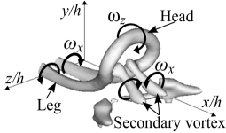
Hairpin vortices, which constitute a vortex structure with longitudinal vortices called legs, develop along a wall surface. Previous studies (Torii et al., 1994; Senaha et al., 2001) have shown that such longitudinal vortices are less likely to decay, thus facilitating fluid mixing and heat transfer in the wake. Acarlar and Smith (1987) investigated a hairpin vortex in the wake of a hemispherical protuberance in a visualization experiment and found that both legs of the hairpin vortex extend in the downstream direction. The present authors (Yanaoka et al., 2007b, 2008) previously reported that hairpin vortices cause high turbulence in the wake and increase heat transfer, as determined from a three-dimensional numerical analysis of a hairpin vortex generated behind a hill. Li et al. (2019) investigated the coherent structure and heat transfer in the turbulent boundary layer along the wall of a channel with a rib tabulator and found that multiple hairpin vortices occur, increasing the heat transfer coefficient and turbulence. Therefore, the formation of hairpin vortices is expected to be an effective method for mixing substances and promoting heat transfer.
When multiple ribs are installed on a wall, the wakes behind the ribs interfere with each other. Therefore, the vortex characteristics in a wake change depending on the arrangement of the ribs. Kurita and Yahagi (2008) investigated the wake of heated cylinders arranged perpendicular to the flow direction. They found that the wake becomes symmetric (asymmetric) when the cylinder spacing is wide (narrow). Hanson et al. (2009) showed that when two cylinders are placed perpendicular to the flow direction, there are two vortex shedding frequencies when the distance between the cylinders is narrow. Studies on such wake interference have not targeted flow fields with multiple hairpin vortices (Moriya and Sakamoto, 1985; Sayers and Saban, 1994; Zhou et al., 2002; Wang and Zhou, 2005; Li and Sumner, 2009). In a complex flow field with multiple hairpin vortices that generate high turbulence, it is considered that the turbulence and heat transfer change significantly due to the interference between the hairpin vortices.
In this study, we perform a numerical analysis of a flow field where multiple hairpin vortices exist in the wake behind staggered hills in a laminar boundary layer and clarify the effects of the interference between hairpin vortices on turbulence and heat transfer.
2 Fundamental equation and numerical procedures
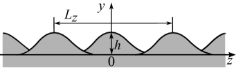
Figure 1 shows the flow configuration and coordinate system. The origin is on the wall surface and the -, -, and -axes are the streamwise, cross-streamwise, and spanwise directions, respectively. The velocities in these directions are denoted as , , and , respectively, and the temperature is denoted as . A uniform flow originates upstream and a laminar boundary layer develops downstream. The free stream velocity and temperature are denoted as and , respectively. In this study, similar to Acarlar and Smith (1987), a rib is placed in the laminar boundary layer and a hairpin vortex is generated using flow separation. The rib has the same shape as that used in the experiment of Simpson et al. (2002); it is a hill with a height of and a radius of . The height of the hill is given as follows:
| (1) |
where , is the radius, is the hill height, is the hill radius, is the Bessel function of the first kind, and is the modified Bessel function of the first kind.
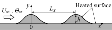
(a) - plane
(b) - plane
In this study, to create a flow field with multiple hairpin vortices, hill-shaped ribs are arranged parallel to the spanwise direction on the wall surface, as shown in figure 1, and installed in a staggered pattern. The hill spacing in the streamwise direction is and that in the spanwise direction is . The spanwise distance between the vertices of the hills in the first and second rows is .
This study deals with the three-dimensional flow of an incompressible viscous fluid with constant physical properties. The continuity, Navier-Stokes, and energy equations in Cartesian coordinates are transformed into those in a general coordinate system. The governing equations are solved using the simplified marker and cell method (Amsden and Harlow, 1970) extended to the collocated grid. The pressure interpolation proposed by Rhie and Chow (1983) is used to remove spurious errors. The Crank-Nicolson method is applied to discretize the time derivative and then time marching is performed. The second-order central difference scheme is used to discretize the spatial derivative.
3 Details of calculation
In this study, the hill spacing in the streamwise direction is fixed at and the spanwise hill spacing is or . We vary to investigate the effect of interference between hairpin vortices on the flow field and heat transfer. The computational region is to in the -direction, 0 to in the -direction, and to ( to ) for () in the -direction.
For the boundary conditions of the velocity field, the Blasius velocity profile is given at the inlet and convective boundary conditions are used at the outlet. No-slip boundary conditions are applied on the walls. Slip boundary conditions are assumed at the upper boundary away from the bottom surface. For the boundary condition of the temperature field, a uniform temperature is given at the inlet and the convective boundary condition is used at the outlet. The hill surface and bottom wall are heated with a constant heat flux. A zero gradient of the temperature is assumed at the upper boundary. Periodic boundary conditions are applied in the spanwise direction for the velocity and temperature.
The numerical calculations are performed under the Reynolds number , which is defined by and , and the Prandtl number . The velocity boundary layer thickness at the inlet is set so that the thickness becomes at without the hill. The boundary layer thickness at the entrance is , the displacement thickness is , and the momentum thickness is . The Reynolds numbers defined by these thicknesses and are , , and , respectively. These conditions are the same as those in previously reported calculations (Yanaoka et al., 2007b, 2008).
Grids with dimensions of (grid7-1), (grid7-2), and (grid7-3) are used to confirm the grid dependency on the calculation result for . Grids with dimensions of (grid4-1), (grid4-2), (grid4-3), and (grid4-4) are used for . The grids are dense near the lower wall surface and hills. The minimum grid widths for are (grid7-1), (grid7-2), and (grid7-3). The minimum grid widths for are (grid4-1), (grid4-2), (grid4-3), and (grid4-4). For each value, we investigated the effect of the number of grid points on the calculation results. We confirmed that the differences between the results obtained with grid7-2 and grid7-3 for and between those obtained with grid4-3 and grid4-4 for were small. The results obtained using the fine grids, namely grid3 for and grid4 for , are shown to clarify the turbulence due to the vortex structure in detail.
To clearly show the interference between hairpin vortices in the wake of a hill, we expanded the visualization region in the spanwise direction to visualize the areas from to for and from to for .
(a) Top view
(b) Side view downstream of hill in first row
(c) Side view downstream of hill in second row
4 Results and discussion
4.1 Vortex structure in wake
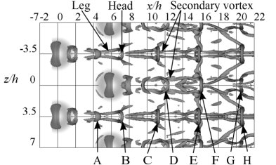
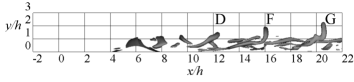
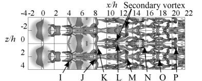
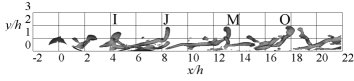
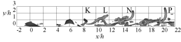
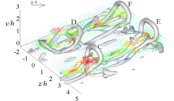
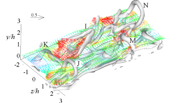
To clarify the vortex structure in the flow field, figures 2 and 3 show the top and side views of the isosurface of curvature calculated from the equipressure surface for and , respectively. This method of visualizing the vortex structure was used in our previous research (Yanaoka et al., 2007b, a, 2008). In the figures, the hairpin vortices are labelled A to P. For and , the separated shear layer at the top of each hill becomes unstable downstream and rolls up into a vortex. Such flow is similar to that for a single hill (Yanaoka et al., 2007b, 2008).
(a) Top view
(b) Side view downstream of hill in first row
(c) Side view downstream of hill in second row
(a) Perspective view

(b) Velocity fluctuation vectors
(c) Schematic diagram
For , shown in figure 2(a), the vortices rolled up at and behind the hill rows grow into hairpin vortices A and D around and downstream, respectively. Under the heads of hairpin vortices C and D, a secondary vortex forms. This secondary vortex consists of two streamwise vortices toward the wall surface. As can be seen from figures 2(b) and (c), as the hairpin vortex generated from each hill develops, the head rises and the angle between the legs and the wall increases. Because the shape and behaviour of such hairpin vortices are similar to those of a hairpin vortex generated from a single hill (Yanaoka et al., 2007b, 2008), it is considered that the interference between hairpin vortices is weak in this flow field.
For , shown in figure 3(a), the vortex rolled up at behind the hills in the first row grows into hairpin vortex I around . When the hairpin vortex moves downstream, its head shape changes in the same way as hairpin vortices J, M, and O. In addition, the vortex rolled up at behind the hill in the second row grows into hairpin vortex K around . Downstream of hairpin vortex K, hairpin vortex L near deforms in the same way as hairpin vortices N and P. Below the heads of hairpin vortices L and M, secondary vortices are observed, as in the case of . From figure 3(b), it can be seen that the heads of hairpin vortices J, M, and O generated from the hills in the first row are at the same height. In contrast, as shown in figure 3(c), the head of the hairpin vortex generated from the hill in the second row rises sharply downstream. The position of the head of hairpin vortex P reaches around . The shape and behaviour of such hairpin vortices are very different from those of hairpin vortices generated from a single hill (Yanaoka et al., 2007b, 2008). Therefore, in the flow field for , it is considered that the hairpin vortices strongly interfere with each other.
Hairpin vortices generated for and 4h are periodically shed in the wake behind each hill. The vortex shedding frequency is for and for , indicating that it is mostly independent of hill spacing. These values are very close to the calculation result () for a single hill (Yanaoka et al., 2007b, 2008). Moreover, the calculation result is within the range of experimental results ( to ) at (Acarlar and Smith, 1987).
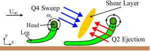
Figures 4(a) and (b) show an enlarged view of hairpin vortex C in figure 2 and the velocity fluctuation vector in the - plane, respectively, and figure 4(c) shows the flow around the hairpin vortex. As shown in figure 4(a), two streamwise vortices toward the wall surface appear below the head of hairpin vortex C. Such secondary vortices, which also exist under the heads of hairpin vortices D, L, and M, correspond to the horn-shaped secondary vortex reported in previous studies (Yanaoka et al., 2007b, 2008). In addition, it is found from figure 4(b) that a flow () rotating clockwise is induced around the head of hairpin vortex C. The flow from the lower side of the hairpin vortex head to the upstream mainstream side is called Q2 ejection. The flow from the upstream of the hairpin vortex head to the downstream wall surface is called Q4 sweep (figure 4(c)). The classification of such flow phenomena was reported by Yang et al. (2001). Around in figure 4(b), the flows due to Q2 ejection and Q4 sweep collide, generating a shear layer. The formation of such a shear layer has been previously observed (Yang et al., 2001; Yanaoka et al., 2007b, 2008).
(a)
(b)
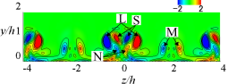
Next, to clarify the three-dimensional flow due to the hairpin vortices for and , figure 5 shows the velocity fluctuation vector at and the isosurface of the curvature calculated from the equipressure surface. The position of is below the head of each hairpin vortex. As in figures 2 and 3, the hairpin vortices in figure 5 are labelled C to F and J to M. The Q2 ejection observed in hairpin vortex C in figure 4(b) and the ascending and descending flows due to the legs occur around all the hairpin vortices. For , the interference between hairpin vortices is stronger than that at , and thus strong velocity fluctuations occur in the entire flow field and Q2 ejection due to the head of hairpin vortex L strengthens.
(a)
(b)

(a) First hill

(b) Second hill

(a) First hill

(b) Second hill
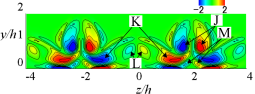
Figure 6 shows the streamwise vorticity () distribution in the - plane for . Regions J to N are the distributions generated by the legs of hairpin vortices J to N, and region S is the distribution generated by the secondary vortex of hairpin vortex L. At , high-vorticity region K appears below high-vorticity region J. At downstream, high-vorticity regions L and S are generated by the legs of hairpin vortex L and the secondary vortex, respectively.
When , as can be seen from figures 3(a) and 6(a), both legs of hairpin vortex K are attracted to hairpin vortex J, which has high vorticity. As a result, the legs are spread. At this time, because the interference between the hairpin vortices becomes strong, the structure of hairpin vortex K changes significantly, and downstream, hairpin vortex K develops like hairpin vortex L with a small distance between the legs and high vorticity (figure 6(b)). In hairpin vortex L, the distance between the legs narrows, and the legs significantly interfere with each other. Thus, the self-induction velocity between the legs increases, and Q2 ejection becomes strong. As a result, the head of hairpin vortex L rises sharply. Toward the downstream, because hairpin vortex M, whose vorticity weakens, is attracted to the developed secondary vortex S, the legs of hairpin vortex M spread. In hairpin vortex N, the shape of the head is close to that for . As the interference between adjacent hairpin vortices is weak for , the vortex structure and behaviour of the hairpin vortex in the wake do not significantly change like hairpin vortices K, L, and M for .
4.2 Mean properties
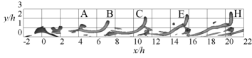
Figures 7 and 8 show time-averaged streamwise velocity and temperature distributions in the cross-sections of (), (), (), and (), where the hairpin vortices generated from the hills in the first and second rows respectively exist. The streamwise velocity is compared with the experimental values at and for reported by Acarlar and Smith (1987) and the calculation results at and for previously reported by the present authors (Yanaoka et al., 2007b, 2008). The temperature is compared with the results at and previously reported by the present authors (Yanaoka et al., 2007b, 2008). The positions of the calculation results shown in figures 7(b) and 8(b) coincide with the streamwise distance from the hill vertex in previously reported results (Acarlar and Smith, 1987; Yanaoka et al., 2007b, 2008). At in figure 7(a) and in figure 7(b), the maximum values generated by the legs of the hairpin vortex appear around in the distributions for and , as is the case for the previously reported results (Acarlar and Smith, 1987; Yanaoka et al., 2007b, 2008). As both legs of the hairpin vortex develop, they approach the vicinity of the wall surface, and a secondary vortex is generated under the head. Therefore, the flows near the wall surface at and are faster than those at and , respectively.
For in figure 7(b), the distribution at well agrees with the previously reported result for a single hill (Yanaoka et al., 2007b, 2008) but the distribution shape at is different from the previously reported shape. This result suggests that the hairpin vortices interfere with each other even for . In the distribution for at in figure 7(b), the flow in the region from to 1.1 is faster than that in the distribution for and previously reported results (Yanaoka et al., 2007b, 2008). This is because the interference between the hairpin vortices narrows the legs of the hairpin vortex generated from the hills in the second row. In addition, the effect of contraction between the hills increases the flow velocity.
All temperature distributions in figure 8 are high from the wall surface to because Q2 ejection and the rotation of the legs of the hairpin vortex lift the hot fluid near the wall. For in figure 8(b), the distribution at well agrees with the previously reported result (Yanaoka et al., 2007b, 2008), similar to the streamwise velocity distribution, whereas the distribution at is slightly different from the previously reported result near the wall surface. The temperature distribution for at in figure 8(b) shows higher values than that for and the previously reported result (Yanaoka et al., 2007b, 2008). This is because the vorticity of the hairpin vortices generated from the hills in the second row increases due to the strong interference between the hairpin vortices, which increases the vertical self-induction velocity and transports the hot fluid to the mainstream side.
From these mean properties, it can be seen that hairpin vortices interfere with each other in a flow field where multiple hairpin vortices exist, and that the interference is weak for but strong for .
(a) ()
(b) ()
(c) ()
(d) ()
4.3 Turbulence characteristics
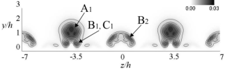
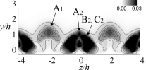
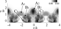
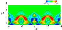
Figure 9 shows the contours of the time-averaged turbulence kinetic energy in the - plane at and 15 for and . Here, high-turbulence regions caused by the head and legs of the hairpin vortex and the secondary vortex are labelled A, B, and C, respectively. In addition, the turbulences caused by the hairpin vortices generated from the hills in the first and second rows are distinguished by subscripts 1 and 2, respectively. At for , the head of the hairpin vortex generated from the hills in the first row forms high-turbulence region A1 around . Turbulence regions B1 and C1 near the wall surface are generated by the two legs of the hairpin vortex and the secondary vortex, respectively. Around , turbulence region B2 is generated by the legs of the hairpin vortex. The above trend is the same at downstream. Because interference between hairpin vortices is weak for , such turbulence distributions generated by hairpin vortices are similar to previously reported results (Gretta and Smith, 1993; Dong and Meng, 2004; Yanaoka et al., 2007b, 2008).
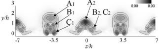
At for , the head of the hairpin vortex generated from the hill in the first row forms turbulence region A1 around . Near , regions A2, B2, and C2 have higher turbulence than those for . This result indicates that the interference between the hairpin vortices remarkably strengthens the hairpin vortex generated from the hill in the second row and that the secondary vortex develops into a strong vortex. Furthermore, because the distance between the legs of the hairpin vortex is narrowed in this region, the strong interference between the legs is considered to be a factor in such high turbulence. At downstream, because the legs of the hairpin vortex at are widened by the neighbour hairpin vortex, high-turbulence regions B1 and C1 respectively generated by the legs of the hairpin vortex and the secondary vortex, approach regions B2 and C2. Therefore, the high-turbulence region spreads in the spanwise direction near the wall surface.

(a) First hill

(b) Second hill
Figure 10 compares the turbulence intensity distributions of the streamwise velocity fluctuations in the cross-sections of (), (), (), and () with the previously reported results (Acarlar and Smith, 1987; Yanaoka et al., 2007b, 2008). The plane position is the same as that in figures 7 and 8. The position of the calculation result shown in figure 10(b) coincides with the streamwise direction distance from the hill vertex in the previously reported results (Acarlar and Smith, 1987; Yanaoka et al., 2007b, 2008). In the distributions of and at shown in figure 10(a), two maxima are generated around and 0.5 by the head and the two legs of the hairpin vortex, respectively. At downstream, the maximum value on the mainstream side occurs at a high position as the head rises due to the development of the hairpin vortex. Near the wall surface, the legs of the hairpin vortex approach the wall surface and the secondary vortex develops, so high turbulence is maintained. In the distributions of and in figure 10(b), two maxima are also generated by the head and the two legs of the hairpin vortex as in figure 10(a).
In the distribution for at in figure 10(a), higher turbulence occurs near than that for because the hairpin vortex generated from the hill in the first row interacts with the flow entering between the hills in the first row. In the distribution for at in figure 10(b), the turbulence is significantly higher than that for , previously reported results (Acarlar and Smith, 1987; Yanaoka et al., 2007b, 2008), and the result for at in figure 10(a). This is because the strong interference between the hairpin vortices strengthens the interference between the legs of the hairpin vortices generated from the hills in the second row, and Q2 ejection and the secondary vortex also strengthen. In the distribution for at downstream, the turbulence due to the head occurs at a higher position than that for and the previously reported results (Acarlar and Smith, 1987; Yanaoka et al., 2007b, 2008). The turbulence is high near the wall surface due to the two legs of the strengthened hairpin vortex and the secondary vortex.
Next, figure 11 shows the streamwise variation of the area- and time-averaged turbulence kinetic energy in the - plane. Because the hairpin vortex generated from the hill in the first row develops, the value of begins to increase from for and for . Downstream from the vicinity of for and for , the hairpin vortices generated from the hills in the first and second rows begin to interfere with each other, so the value of further increases. Near for and for , the value of decreases because the hairpin vortex decays and the interference between the hairpin vortices begins to weaken. The maximum value of around for reaches 4.2 times the maximum value around for , and the interference between hairpin vortices is remarkably strong for .
4.4 Heat transport property

(a) Vertical velocity fluctuation (contour interval is from to )
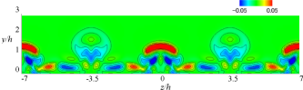
(b) Temperature fluctuation (contour interval is from to )
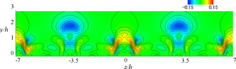
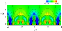
To investigate the heat transport in the flow field, figure 12 shows the contours of the instantaneous vertical velocity and temperature fluctuations in the - plane at , where high-turbulence kinetic energy was found for and in figure 11. For , the vertical velocity fluctuation around 2 and is negative. This fluctuation is mainly due to the Q4 sweep induced around the head of the hairpin vortex. Because the low-temperature fluid of the mainstream is transported toward the wall surface by the Q4 sweep, the temperature fluctuation becomes negative around in this region. The Q2 ejection by the head of the hairpin vortex and the rotating flow of the legs occur. Therefore, from to around , the vertical velocity fluctuation becomes positive. At that time, because the high-temperature fluid is lifted by upward flow, the temperature fluctuation around becomes an arch-shaped positive distribution centred on . Near the wall surface around , the vertical velocity and temperature fluctuations become negative due to the rotation of the secondary vortex.

(a)
(b)
The trend of is similar to that of . For , the hairpin vortex generated from the hill in the second row is strengthened by the interference with the adjacent hairpin vortex, and the secondary vortex strengthens accordingly. Therefore, strong fluctuations occur in the entire flow field, compared with the result for .
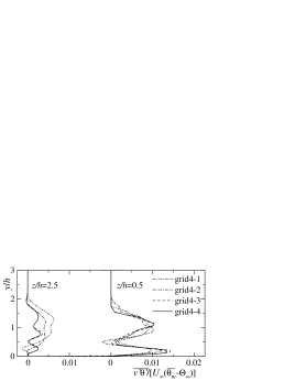
Next, figure 13 shows the distributions of the turbulent heat flux at the planes of (), (), (), and (), where the legs of the hairpin vortex generated from the hill in the first and second rows exist. In this figure, the results obtained using each grid point are compared. The maximum value of on the mainstream side of each distribution is generated by the head of the hairpin vortex. In addition, the maximum value of appears near the wall surface due to the legs of the hairpin vortex and the secondary vortex. For (grid7-3), the maximum regions are around , and , , 0.5. For (grid4-4), the regions are around , and , . The hairpin vortex generated from the hill in the second row and the secondary vortex are strengthened by the strong interference between the hairpin vortices. Therefore, in the distribution for at , is higher than that for , and heat transport is active.
There are differences in the results obtained with grid7-1 and grid7-2 for and those obtained with grid4-1, grid4-2, and grid4-3 for . In contrast, the distributions obtained with grid7-2 and grid7-3 for and those obtained with grid4-3 and grid4-4 for well agree. Therefore, grid7-1 for and grid4-1 and grid4-2 for are coarse grids, and it can be said that the grid resolution is low.
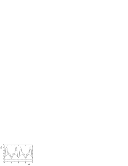
Next, figure 14 shows the variation of the instantaneous Nusselt number in the spanwise direction. Figure 15 shows the time- and spanwise-averaged Nusselt number . The Nusselt number is defined as , where is the local heat transfer coefficient, is the thermal conductivity, and is the heat flux at the wall. In figures 14 and 15, the calculation results are compared with a similarity solution for the laminar boundary layer (Lighthill, 1950), as in the previous studies (Yanaoka et al., 2007b, 2008). Around , , and for , is high because heat transport becomes active due to the flow of the legs of the hairpin vortex and the secondary vortex. In the distribution for , becomes maximum around , , and due to the same factors as those for . As can be seen from figure 3(a), the maximum values around for are strongly influenced by the secondary vortex for the distributions of and by the legs of the hairpin vortex for .
For , is very high around compared to for . This is because the hairpin vortices interfere with each other. As the turbulence is increased by the legs of the strongly developed hairpin vortex and the secondary vortex, heat transport near the wall surface becomes active. In addition, is high at the plane of , where the interference between hairpin vortices is strong. However, because the interference between hairpin vortices weakens downstream and heat transport declines, decreases. for is higher over the entire region in the spanwise direction than for . As a result, for in figure 15 shows a higher value from to 20 than the distribution for and the similarity solution. Therefore, it is clear that the heat transfer coefficient for is high over a wide range of the wake.

(a)
(b)

5 Conclusions
We performed a numerical simulation of the interference and heat transfer between hairpin vortices formed in the wake behind staggered hills in a laminar boundary layer. The obtained findings are summarized as follows.
Hairpin vortices are periodically shed in the wake of a row of hills, causing interference between the hairpin vortices. As the spanwise distance between the hills decreases, the interference increases and the hairpin vortex becomes strong. Then, because the distance between the legs of the hairpin vortex becomes narrow, the interference between the legs and Q2 ejection becomes strong. As a result, the head of the hairpin vortex rises sharply.
When the hill spacing decreases, the turbulence caused by the head and legs of the hairpin vortex generated from the hill in the second row increases remarkably. In addition, the secondary vortex also generates turbulence. Downstream, the hairpin vortex and secondary vortex are attracted to adjacent hairpin vortices, causing widespread high turbulence in the spanwise direction near the wall surface.
Regardless of hill spacing, the Q2 ejection and Q4 sweep due to the hairpin vortex occur, and the secondary vortex forms around the hairpin vortex, activating heat transport and increasing the heat transfer coefficient in the wake. When the hill spacing becomes narrower, the interference between the hairpin vortices strengthens the legs and the secondary vortex, and heat transport near the wall surface becomes very active. In addition, the heat transfer increases over a wide range of the wake because the legs of hairpin vortices flowing downstream are spread in the spanwise direction.
Acknowledgements. The numerical results in this research were obtained using supercomputing resources at the Cyberscience Center, Tohoku University. This research did not receive any specific grant from funding agencies in the public, commercial, or not-for-profit sectors. We would like to express our gratitude to Associate Professor Yosuke Suenaga of Iwate University for his support of our laboratory. The authors wish to acknowledge the time and effort of everyone involved in this study.
Declaration of interests. The authors report no conflicts of interest.
Author ORCID.
H. Yanaoka https://orcid.org/0000-0002-4875-8174.
Author contributions. H. Y. conceived and planned the research and developed the calculation method and numerical codes. T. Y. performed the simulations. All authors contributed equally to analysing data, reaching conclusions, and writing the paper.
References
- Acarlar and Smith (1987) Acarlar, M.S., Smith, C.R., 1987. A study of hairpin vortices in a laminar boundary layer. Part 1. Hairpin vortices generated by a hemisphere protuberance. J. Fluid Mech. 175, 1–41. doi:doi:https://doi.org/10.1017/S0022112087000272.
- Adrian (2007) Adrian, R.J., 2007. Hairpin vortex organization in wall turbulence. Phys. Fluids 19, 041301. doi:doi:https://doi.org/10.1063/1.2717527.
- Amsden and Harlow (1970) Amsden, A.A., Harlow, F.H., 1970. A simplified MAC technique for incompressible fluid flow calculations. J. Comput. Phys. 6, 322–325. doi:doi:https://doi.org/10.1016/0021-9991(70)90029-X.
- Bake et al. (2002) Bake, S., Meyer, D.G.W., Rist, U., 2002. Turbulence mechanism in Klebanoff transition: A quantitative comparison of experiment and direct numerical simulation. J. Fluid Mech. 459, 217–243. doi:doi:https://doi.org/10.1017/S0022112002007954.
- Bernard (2011) Bernard, P.S., 2011. The hairpin vortex illusion. J. Phys.: Conf. Ser. 318, 062004. doi:doi:https://doi.org/10.1088/1742-6596/318/6/062004.
- Christensen and Adrian (2001) Christensen, K.T., Adrian, R.J., 2001. Statistical evidence of hairpin vortex packets in wall turbulence. J. Fluid Mech. 431, 433–443. doi:doi:https://doi.org/10.1017/S0022112001003512.
- Dong and Meng (2004) Dong, S., Meng, H., 2004. Flow past a trapezoidal tab. J. Fluid Mech. 510, 219–242. doi:doi:https://doi.org/10.1017/S0022112004009486.
- Green et al. (2007) Green, M.A., Rowley, C.W., Haller, G., 2007. Detection of Lagrangian coherent structures in three–dimensional turbulence. J. Fluid Mech. 572, 111–120. doi:doi:https://doi.org/10.1017/S0022112006003648.
- Gretta and Smith (1993) Gretta, W.J., Smith, C.R., 1993. The flow structure and statistics of a passive mixing tab. J. Fluids Eng. 115, 255–263. doi:doi:https://doi.org/10.1115/1.2910133.
- Hanson et al. (2009) Hanson, R., Mohany, A., Ziada, S., 2009. Flow–excited acoustic resonance of two side–by–side cylinders in cross–flow. J. Fluids Struct. 25, 80–94. doi:doi:https://doi.org/10.1016/j.jfluidstructs.2008.03.008.
- Kurita and Yahagi (2008) Kurita, E., Yahagi, Y., 2008. Vortex structure behind highly heated two cylinders in parallel arrangements. JSME, Ser. B 74, 1600–1608. doi:doi:https://doi.org/10.1002/htj.20244. (in Japanese).
- Li and Sumner (2009) Li, H., Sumner, D., 2009. Vortex shedding from two finite circular cylinders in a staggered configuration. J. Fluids Struct. 25, 479–505. doi:doi:https://doi.org/10.1016/j.jfluidstructs.2008.11.001.
- Li et al. (2019) Li, H., Yu, T., Wang, D., Xu, H., 2019. Heat–transfer enhancing mechanisms induced by the coherent strucures of wall–bounded turbulence in channel with rib. Int. J. Heat Mass Transf. 137, 446–460. doi:doi:https://doi.org/10.1016/j.ijheatmasstransfer.2019.03.122.
- Lighthill (1950) Lighthill, M.J., 1950. Contributions to the theory of heat transfer through a laminar boundary layer. Proc. R. Soc. Lond. A 202, 359–377. doi:doi:https://doi.org/10.1098/rspa.1950.0106.
- Lloyd et al. (2022) Lloyd, C.J., Dorrell, R.M., Caulfield, C.P., 2022. The coupled dynamics of internal waves and hairpin vortices in stratified plane poiseuille flow. J. Fluid Mech. 934, A10. doi:doi:https://doi.org/10.1017/jfm.2021.1007.
- Lu et al. (2013) Lu, P., Yan, Y., Liu, C., 2013. Numerical investigation on mechanism of multiple vortex rings formation in late boundary–layer transition. Comput. Fluids 71, 156–168. doi:doi:https://doi.org/10.1016/j.compfluid.2012.10.008.
- Moriya and Sakamoto (1985) Moriya, M., Sakamoto, H., 1985. Fluctuating pressures and forces acting on downstream cylinder in staggered arrangement. JSME, Ser. B 51, 3017–3022. doi:doi:https://doi.org/10.1299/kikaib.51.3017. (in Japanese).
- Rhie and Chow (1983) Rhie, C.M., Chow, W.L., 1983. Numerical study of the turbulent flow past an airfoil with trailing edge separation. AIAA J. 21, 1525–1532. doi:doi:https://doi.org/10.2514/3.8284.
- Sayers and Saban (1994) Sayers, A.T., Saban, A., 1994. Flow over two cylinders of different diameters: The lock–in effect. J. Wind. Eng. Ind. Aerodyn. 51, 43–54. doi:doi:https://doi.org/10.1016/0167-6105(94)90076-0.
- Schlatter et al. (2014) Schlatter, P., Li, Q., Orlu, R., Hussain, F., Henningson, D.S., 2014. On the near–wall vortical structures at moderate Relynolds numbers. Eur. J. Mech. B Fluids 48, 75–93. doi:doi:https://doi.org/10.1016/j.euromechflu.2014.04.011.
- Senaha et al. (2001) Senaha, I., Ishikawa, S., Oyakawa, K., 2001. Studies on structure of heat transfer enhancement in tube with longitudinal vortices being generated. JSME, Ser. B 67, 2754–2761. doi:doi:http://dx.doi.org/10.1299/kikaib.67.2754. (in Japanese).
- Simpson et al. (2002) Simpson, R.L., Long, C.H., Byun, G., 2002. Study of vortical separation from an axisymmetric hill. Int. J. Heat Fluid Flow 23, 582–591. doi:doi:https://doi.org/10.1016/S0142-727X(02)00154-6.
- Torii et al. (1994) Torii, K., Nishino, K., Nakayama, K., 1994. Mechanism of heat–transfer enhancement by longitudinal vortices in a flat–plate boundary layer. JSME, Ser. B 60, 997–1004. doi:doi:https://doi.org/10.1299/KIKAIB.60.997. (in Japanese).
- Wang and Zhou (2005) Wang, Z.J., Zhou, Y., 2005. Vortex interactions in a two side–by–side cylinder near–wake. Int. J. Heat Fluid Flow 26, 362–377. doi:doi:https://doi.org/10.1016/j.ijheatfluidflow.2004.10.006.
- Yanaoka et al. (2007a) Yanaoka, H., Inamura, T., Kawabe, S., 2007a. Turbulence and heat transfer of a hairpin vortex formed behind a cube in a laminar boundary layer. Numer. Heat Tr., A-Appl. 52, 973–990. doi:doi:https://doi.org/10.1080/10407780701389590.
- Yanaoka et al. (2007b) Yanaoka, H., Inamura, T., Suenaga, Y., Kobayashi, Y., 2007b. Numerical simulation of vortex structures and heat transfer behind a hill in a laminar boundary layer. JSME, Ser. B 73, 2357–2544. doi:doi:https://doi.org/10.1299/kikaib.73.2537. (in Japanese).
- Yanaoka et al. (2008) Yanaoka, H., Inamura, T., Suenaga, Y., Kobayashi, Y., 2008. Numerical simulation of vortex structures and heat transfer behind a hill in a laminar boundary layer. Heat Trans. Asian Res. 37, 398–411. doi:doi:https://doi.org/10.1002/htj.20217.
- Yang et al. (2001) Yang, W., Meng, H., Sheng, J., 2001. Dynamics of hairpin vortices generated by a mixing tab in a channel flow. Exp. Fluids 30, 705–722. doi:doi:https://doi.org/10.1007/s003480000252.
- Zhou et al. (1999) Zhou, J., Adrian, R.J., Balachandar, S., Kendall, T.M., 1999. Mechanisms for generating coherent packets of hairpin vortices in channel flow. J. Fluid Mech. 387, 353–396. doi:doi:https://doi.org/10.1017/S002211209900467X.
- Zhou et al. (2002) Zhou, Y., Zhang, H.J., Yiu, M.W., 2002. The turbulent wake of two side–by–side circular cylinders. J. Fluid Mech. 458, 303–332. doi:doi:https://doi.org/10.1017/S0022112002007887.