Review on Panoramic Imaging and Its Applications in Scene Understanding
Abstract
With the rapid development of high-speed communication and artificial intelligence technologies, human perception of real-world scenes is no longer limited to the use of small Field of View (FoV) and low-dimensional scene detection devices. Panoramic imaging emerges as the next generation of innovative intelligent instruments for environmental perception and measurement. However, while satisfying the need for large-FoV photographic imaging, panoramic imaging instruments are expected to have high resolution, no blind area, miniaturization, and multidimensional intelligent perception, and can be combined with artificial intelligence methods towards the next generation of intelligent instruments, enabling deeper understanding and more holistic perception of real-world surrounding environments. Fortunately, recent advances in freeform surfaces, thin-plate optics, and metasurfaces provide innovative approaches to address human perception of the environment, offering promising ideas beyond conventional optical imaging. In this review, we begin with introducing the basic principles of panoramic imaging systems, and then describe the architectures, features, and functions of various panoramic imaging systems. Afterwards, we discuss in detail the broad application prospects and great design potential of freeform surfaces, thin-plate optics, and metasurfaces in panoramic imaging. We then provide a detailed analysis on how these techniques can help enhance the performance of panoramic imaging systems. We further offer a detailed analysis of applications of panoramic imaging in scene understanding for autonomous driving and robotics, spanning panoramic semantic image segmentation, panoramic depth estimation, panoramic visual localization, and so on. Finally, we cast a perspective on future potential and research directions for panoramic imaging instruments.
Index Terms:
Panoramic imaging, panoramic optical system, ultra-wide-angle optical system, computational imaging, intelligent instrument, computer vision, multidimensional perception, scene understanding.I Introduction
Recent advances in high-speed communication and artificial intelligence have led to stronger demand for upgrading traditional imaging systems. Panoramic imaging has a wider Field of View (FoV) than traditional panoramic optical systems and can capture more information about the surrounding environment at a time. It is becoming the next generation of intelligent sensing instruments. They are used in autonomous driving, machine vision inspection, endoscopic medicine, satellite atmospheric inspection, and many other applications. In terms of imaging performance, panoramic imaging faces several common challenges to satisfy the requirements of applications such as machine vision, including FoV, resolution, no blind area, and imaging quality. Another urgent requirement is multidimensional intelligent perception, where panoramic imaging is expected to be combined with intelligent sensors to record, fuse, and perceive higher dimensional information about the surrounding environment. In addition, panoramic imaging is expected to evolve towards lightweight and small-volume structural forms for applications in more space- and weight-constrained scenarios. However, the above requirements usually entail addressing different trade-offs, which make the design of panoramic imaging instruments particularly challenging. Compared with the only previous panoramic imaging survey [1], it is so far back that it does not provide an overview of the flourishing progress in panoramic imaging in the last 20 years [2, 3, 4, 5, 6, 7], which is addressed in this review. Surveys on other sensing have emerged, such as LiDAR [8, 9] or applications in scene understanding [10, 11, 12]. However, a detailed review of panoramic imaging and its applications has not appeared so far. This review fills the gap by combing panoramic imaging and its scenario applications from their origin to the latest developments. Panoramic imaging experienced its first boom in the 1990s, but this boom gradually declined due to the lack of qualified manufacturing equipment and digital information processing systems.
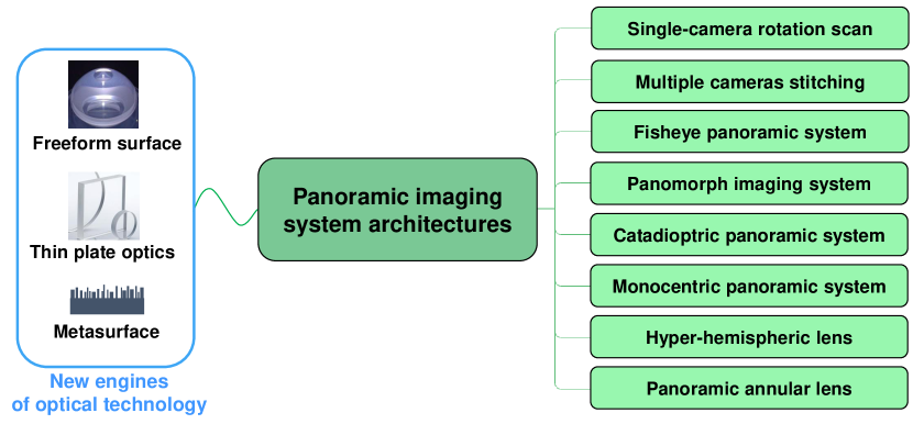
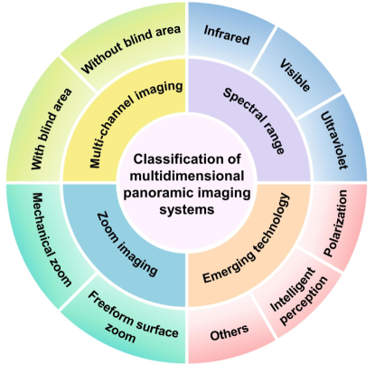
In the past decade, the concept of panoramic imaging has been revisited and has enjoyed a new boom. Emerging technologies such as freeform surfaces [13] and metasurfaces [14] have dramatically reshaped panoramic imaging systems and lit a bright light in the panoramic imaging field. The application of these emerging optical technologies has made a strong impetus for the performance improvement of panoramic optical system architectures (Fig. 1(a)). At the same time, the proposal of the multidimensional panoramic imaging system has enriched the panoramic imaging and played a more powerful role in different application fields (Fig. 1(b)). In this review, we first introduce the basic concepts of panoramic imaging, related design challenges, and potential solutions. Afterwards, we review different architectures of panoramic imaging systems and their characteristics in detail. In addition, we classify and analyze different panoramic imaging systems according to their multidimensional imaging modalities and briefly introduce the emerging optical technologies that are currently being equipped for panoramic imaging. Then, we summarize and discuss the applications of panoramic imaging in scene understanding in detail. Finally, this review provides a comprehensive overview and outlook in the field of panoramic imaging.
II Key Parameters of Panoramic Imaging Systems
To satisfy the panoramic environment perception, panoramic imaging systems usually face several common challenges, such as field of view, wavelength, F-number, focal length, resolution, imaging quality, and volume [15, 16]. To achieve panoramic imaging systems that meet application scenarios, these key parameters and their trade-offs usually need to be considered before design. Potential solutions can facilitate the design and manufacture of panoramic imaging systems with higher parametric performance. Before discussing each parameter in detail, it is helpful to review the basic definitions of the above parameters.
II-A Definition of Parameters
For panoramic imaging systems, the performance parameters of the optical system are particularly important. In this section, the definitions of the key parameters of panoramic imaging systems are summarized.
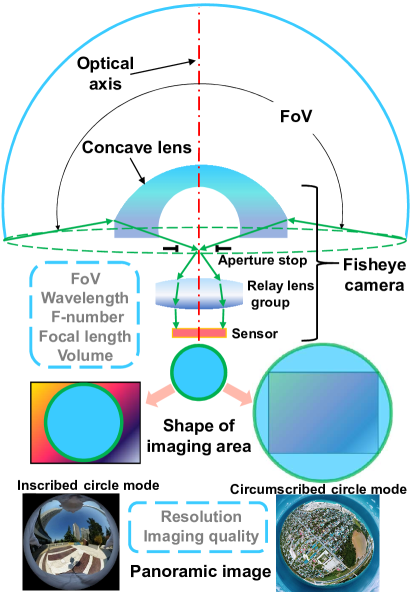
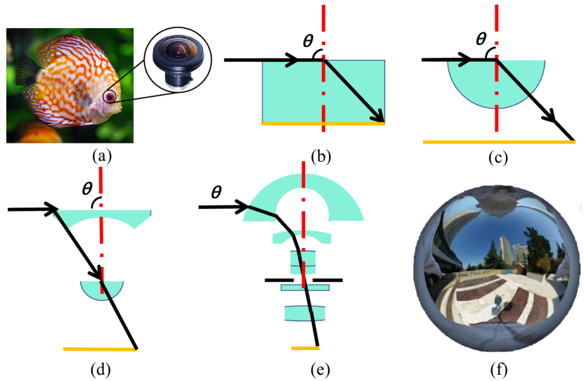
1) Field of View (FoV): In applied optics, there are four ways to express the FoV: angle, object height, paraxial image height, and actual image height. Panoramic imaging instruments usually take the angle as the evaluation standard of the FoV. In practical applications, full angle FoV is generally used. When designing a panoramic optical system, the expression of (Half FoV) is also usually used to represent a panoramic system with a blind area. In optical instruments, the angle formed by the two edges of the maximum range through which the object of the measured target can pass the camera, with the camera of the optical instrument as the vertex, is called the Field of View (FoV) [17, 18]. Here, we take the most common fisheye optical system (Fig. 2) as an example. The FoV determines the ability of the optical instrument to observe the range of the surrounding scene. Compared to other common imaging optical systems, the FoV of a fisheye optical system can usually reach or more. This unique imaging characteristic enables more information about the surrounding environment to be recorded at a time. Common imaging systems typically have a small FoV that captures less information each time. Therefore, panoramic imaging systems have more environmental perception advantages over traditional optical systems with common FoVs and have become a popular development direction for future optical instruments. The concept of metaverse has brought Augmented Reality (AR) and Virtual Reality (VR) display fields into a new round of development, and has also led to the rise of panoramic environment perception [19, 20]. New panoramic imaging instruments enables a broader environmental perception of the real world and transmits the data to artificial intelligence and big data processing for further human awareness and understanding of real-world scenes.
2) Wavelength: In physics, wavelength is the spatial period of a periodic wave [21]. Electromagnetic radiation can be classified by wavelength as radio waves, microwaves, infrared, visible spectrum, ultraviolet, X-rays, and Gamma rays [22, 23]. The spectral range in which the human eye can perceive the world can be described as visible light, usually defined as wavelengths in the range of nanometers (nm) [23]. Light wavelengths longer than the visible spectrum are called infrared. Light wavelengths shorter than the visible spectrum are called ultraviolet. Ultraviolet (UV) wavelengths range from nm to nm and are shorter than visible light, but longer than X-rays [24]. Typically, infrared (IR) wavelengths range from nm to millimeter (mm) [25]. Visible light wavelengths are the most common range for designing panoramic imaging optical systems [16]. To expand human perception of the surrounding environment, UV and IR panoramic imaging systems have emerged to enable a wider spectrum of environmental perception beyond the human visible spectrum wavelengths [26, 27].
3) F-number: It is defined as the ratio of the focal length (in the image space) of an optical system to its entrance pupil diameter [28, 29]. The smaller the F-number, the more light is fed into the optical system and the larger the size of the aperture diaphragm (aperture stop). Small F-number optical systems are also called high-speed imaging systems. Small F-number optical systems generally have a large aperture and greater luminous flux, which can improve shutter speed. In low light condition, this optical system can maintain more light flux, which is good for a night- or darkfield shooting [30]. When shooting moving objects, a small F-number optical system is more suitable for shooting the object clearly with a high-speed shutter. Optical system with small F-number has small depth of field [31]. When shooting, the optical system with smaller depth of field will highlight the target while defocusing the background. A large F-number optical system has a large depth of field, enabling clear imaging of a wide range of scenes at both distant and close range, but with reduced illumination. F-number is a crucial parameter. The smaller the F-number, the wider the scope of applications of the camera. When designing an imaging system, a small F-number optical system is more difficult to design. But it typically has higher imaging quality. Therefore, the F-number of a panoramic system is usually designed to be small enough to achieve a large luminous flux and excellent imaging quality.
4) Focal length: The focal length is the distance from the primary point of the optical system to the focal point[32]. The review of the projection models can help us understand the principles of panoramic imaging. Optical design usually follows five classical projection models [33, 34]. They are rectilinear projection model, equidistant projection model, equisolid angle projection model, orthographic projection model, and stereographic projection model. The equidistant projection model is widely used in the design of large FoV optical systems, and its expression in Equation (1) is:
| (1) |
where is the focal length, is the half FoV, and is the image height. The selection of the sensor is required to be matched with the optical system. Similar to other panoramic optical systems, the fisheye optical system contains two imaging modes: the Inscribed circle mode is illustrated in the bottom left corner of Fig. 2 and the Circumscribed circle mode is illustrated in the bottom right corner of Fig. 2. The rectangle is the sensor and the circle is the imaging circle of the fisheye optical system in the image plane. Panoramic images of these two imaging modes are presented below the corresponding imaging mode schematic. A panoramic system designed with the Inscribed circle imaging mode do not lose the FoV, but waste pixels at the edge of the sensor. To achieve panoramic scene understanding with the largest FoV, this mode is used more frequently in the design stage of panoramic systems. Panoramic systems designed with Circumscribed circle imaging modes lose the FoV at the edges. Sometimes this solution is adopted in the design of optical systems without central blind areas such as fisheye optical systems. When the FoV of a panoramic optical system remains the same value, the larger the focal length and the larger the image height. At the same time, the volume of the designed system will be larger. Its matched sensor tends to have a higher resolution (In the case of a constant sensor pixel size).
5) Resolution: Image resolution generally refers to the ability of a measurement or display system to resolve details. This concept can be measured in the fields of time, space, etc. In panoramic system design, resolution generally refers to the total number of arrays of horizontal and vertical pixels of the sensor, such as for a megapixel sensor [35, 36, 37, 38]. The pixel size and resolution of the sensor jointly determine the optical format of the sensor [39, 40]. For the optical system, optical resolution is relevant to the wavelength and aperture diaphragm size. In specific, the shorter the wavelength and the larger the aperture diaphragm, the higher the resolution of the optical system (In the case of great system aberration correction).
6) Imaging quality: The imaging quality of a panoramic optical system is not a single evaluation criterion. The biggest influence on imaging quality is aberration. Aberrations are mainly divided into spherical aberration, coma, astigmatism, field curvature, distortion, chromatic aberration, and wave aberration [28]. Chromatic aberration can be divided into longitudinal chromatic aberration and lateral chromatic aberration. Longitudinal chromatic aberration is also known as positional chromatic aberration, and lateral chromatic aberration is also known as transverse chromatic aberration. In the process of designing a panoramic optical system, the image quality of a panoramic imaging system is usually evaluated by the spot diagram and the Modulation Transfer Function (MTF) [16]. The optical system needs to follow the aberration design theory to correct the aberration in the design process, and the final design needs to satisfy the uniform relative illumination of each FoVs [41, 42]. In order to make the panoramic imaging instrument more conducive to scene understanding, the relative illumination of the panoramic optical system also needs to be as uniform as possible, and the distortion should be as small as possible to meet the perception accuracy requirements [16].
7) Volume: Miniaturized and lightweight panoramic optical systems will be suitable for more space and weight-constrained scenarios [16]. To facilitate the characterization and comparison of the compactness of panoramic systems, a better way is to use the panoramic system compactness ratio as the volume compactness parameter.
The compact ratio of the panoramic system as shown in Equation (2) can be defined as the ratio of the maximum diameter of the panoramic system to the diameter size of an image on the sensor [43]:
| (2) |
where is the ratio of compactness, is the maximum diameter of the imaging circle on the sensor, and is the maximum lateral diameter of the panoramic optical system.
At present, researchers in the panoramic field are inclined to design small volume, small F-number, and high-resolution panoramic optical systems to satisfy the demand for higher optical performance and compactness for panoramic field photography. At the beginning of the design, the parameters need to be considered and weighed in detail.
| System category | Dynamic scene | Image stitching | Compactness | Blind area | Distortion (In most cases) |
| Single-camera rotation scanning [1, 45, 46] | No | Yes | Low | No | Low |
| Multiple cameras stitching [47, 48, 49] | Yes | Yes | Low | No | Low |
| Fisheye panoramic system [50, 51, 52] | Yes | No | Medium | No | 15%20% (Equidistant projection) |
| Panomorph imaging system [53, 54, 55] | Yes | No | High | No | Distortion correction |
| Catadioptric panoramic system [56, 57] | Yes | No | Medium | Yes | 10% or more (Equidistant projection) |
| Monocentric panoramic system [58, 59, 60, 61] | Yes | Yes | High | No | 1%3% (Monocentric multi-scale imager, Rectilinear projection) |
| 20% (Monocentric lens imager, Equidistant projection) | |||||
| Hyper-hemispheric lens [62, 63, 64] | Yes | No | High | YesNo | Distortion correction |
| Panoramic annular lens [65, 66, 67, 16] | Yes | No | High | YesNo | 1%5% (Equidistant projection) |
II-B Key Parameters Trade-offs and Potential Solutions
In the design process of panoramic optical systems, a larger FoV is usually pursued [68]. The increased FoV will bring greater difficulty in aberration correction. The influence of the aberration of the panoramic imaging system on the imaging quality will be solved in the hardware design stage. Therefore, it is particularly important to evaluate which panoramic system architecture to be used in the optical design process to obtain panoramic images with high imaging quality and a large FoV. At the beginning of the development of panoramic optical systems, multiple cameras stitching [47, 48] or single camera scanning [1] techniques were usually used. Single-camera scanning requires high speed, high frame rate, and high precision to maintain scanning stability. However, this method cannot capture the surrounding environment in real time [69]. On the other hand, multiple cameras stitching technology needs to rely on post-algorithm stitching and correction, and there are still errors in camera calibration and correction [47]. The multiple cameras stitching approach usually brings greater device volume and power consumption, as well as the inevitable high price and arithmetic consumption. Subsequent developments in the fisheye optical system use a refractive optical path for single-camera large FoV imaging [51, 70]. The optical path to satisfy the large FoV aberration correction makes the optical path smooth, usually using more negative lenses in the front to deflect the direction of the light path for large FoV [71]. To reduce the number of lenses used, the difficulties of design, processing, and assembly, high refractive index materials are usually used in the design [52]. Although highly refractive materials have a greater ability to refract light, they tend to be more expensive. To further reduce the volume of the system, new panoramic imaging architectures such as catadioptric panoramic system [57], hyper-hemispheric lens [63], panoramic annular lens [16], etc. have emerged. These new architectures usually use a catadioptric optical path to collect the light from a large FoV into a relay lens group and then perform aberration correction. The parameter comparison of different panoramic imaging system architectures is shown in Table I. Each of these panoramic imaging systems has its own architecture, which will be discussed in detail in the next section.
To achieve higher relative illumination and higher optical resolution, small F-number panoramic optical systems have emerged [66]. Long focal length panoramic imaging systems [72, 15] are able to match high-resolution imaging sensors, thus, enabling detailed observation of the panoramic environment. The human eye can only perceive a very narrow spectrum of visible light in electromagnetic waves, which is approximately nm [23]. To provide higher-dimensional detection of the real environment, panoramic imaging systems in the infrared [73, 48, 57], visible [74, 68], and ultraviolet [26, 75] wavelengths have been designed in succession. Not only from the light wave spectrum but also the polarized light [43, 66] can be used for the design of panoramic systems. The use of panoramic optical systems to broaden the human perception of the surrounding environment has become a new trend in the development of panoramic imaging systems. Multidimensional panoramic perception will broaden human understanding of the real environment and provide a deeper understanding and awareness of the real world. Meanwhile, zoom panoramic optical systems [76, 77] can switch between large and small FoVs in the panoramic range to achieve detailed detection of key areas of interest. To obtain a wider observation FoV, multi-channel panoramic systems [78, 79] have also been proposed. These multi-channel panoramic imaging systems usually have larger FoVs with different views. They have certain advantages over single-channel panoramic systems. Catadioptric panoramic optical system usually have a central blind area [62]. To eliminate this tricky drawback, dichroic films [80] and polarization techniques [43, 66] were introduced to eliminate the blind areas. Conventional panoramic systems are designed using spherical surfaces [15, 67]. The optical lens design techniques use the accumulation of optical paths to modulate the beam [81]. As the FoV increases, it becomes more difficult to correct the optical aberration and more lenses are usually used. Such techniques make the design and manufacture of higher-performance compact panoramic systems more difficult. It also makes assembly more difficult and brings an inevitable increase in volume and price.
Fortunately, the rapid development of high-precision manufacturing technology has made new types of optical surfaces possible. Freeform surface [76, 82], thin-plate optics [83], and metasurface [84] technologies provide powerful engines for miniaturization and high imaging performance of panoramic imaging systems. These technologies offer more freedom degrees to optimize the design of panoramic optical systems, allowing for better image quality to an extreme extent, while reducing the system volume [82]. In application areas, panoramic imaging devices are becoming promising filming devices for autonomous driving, medical treatment, satellite navigation, etc [66, 85]. Combined with artificial intelligence and multidimensional sensor technology, panoramic imaging will have broader application scenarios and become a new trend in photographic instruments.
III Architectures and Properties of Panoramic Imaging Systems
III-A Single Camera Scanning and Multiple Cameras Stitching
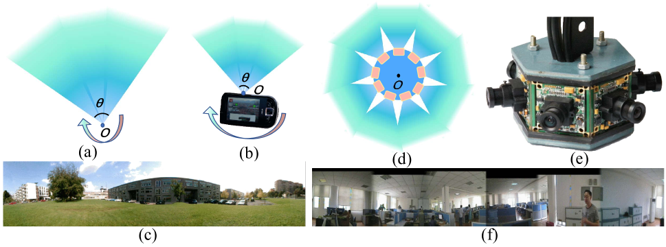
FoVs stitching is a method of using multiple FoVs to capture and stitch together to achieve large-FoV images [86, 87, 88]. This technology is implemented in single-camera scanning and multi-camera stitching methods. Single-camera scanning uses a high-precision mechanical rotating stage to rotate a single camera to create a panoramic view. The shooting principle is shown in Fig. 3(a), where the optical system is scanned around the center point to form an image with a large FoV. Using a mobile phone, a large-FoV panoramic image can be captured, as shown in Fig. 3(b), and the captured image is illustrated in Fig. 3(c) [45]. A similar single-camera scan case is the installation of Nikon 990 mounted on Kaidan Kiwi 990. It can form a large FoV image of [1]. This imaging method can be applied to shoot scenes in a relatively static environment, which requires high scanning accuracy for mechanical devices. The camera cannot achieve gaze imaging because it takes some time to rotate and scan during the shooting. Using a prism to flip the FoV and rotate the shot is a similar scheme [46].
Another common FoV-stitching technique is to use multiple cameras for stitching shots [89]. Multiple cameras shot simultaneously to achieve surround-view image, and the shooting schematic is shown in Fig. 3(d). In [47], a case of FoVs stitching using six visible light cameras is discussed (Fig. 3(e)). The captured image is shown in Fig. 3(f). Due to the inconsistency of the parameter settings and installation angles of each camera, the image stitching is affected. Long-wave infrared optical materials are usually costly. Adopting the multi-camera stitching panoramic imaging technique, Cowan et al. [48] achieved a low-cost long-wave infrared panoramic photography using nine circumferential arrays lined up with small-sized long-wave infrared cameras. This stitching method requires multiple sensors and image stitching algorithms. It requires high positioning and calibration between multiple cameras. A similar design is proposed in [49], which used four visible band cameras to synthesize a low-cost portable polycamera for stereo imaging. With the example of a two-mirror pyramid panoramic cameras, [90] illustrated optimizing the pyramid’s geometry and the selection and placement of imager clusters to maximize the FoV, sensor utilization, and image uniformity. This analysis can be extended and applied to other designs based on pyramid panoramic cameras.
III-B Fisheye Panoramic System
Compared with the FoVs stitching method to obtain panoramic images, using a single camera has the advantages of simple system structure, no need for stitching algorithms, low cost, and stable installation. The most classic way is to use a fisheye optical system. It is called the fisheye optical system because its first lens is protruding and its structure is similar to a fisheye, as shown in Fig. 4(a) [91]. In 1905, Wood [92] presented a prototype of an underwater wide-angle pinhole camera in chapter four of his book Physical Optics, as shown in Fig. 4(b). In 1922, Bond [93] designed a hemispherical lens with a pupil in the center of curvature for cloud recording, as illustrated in Fig. 4(c). In 1924, Hill [94] proposed a hill sky lens, adding a meniscus lens before the hemispherical lens, as depicted in Fig. 4(d). Fig. 4(e) was the first prototype of the modern fisheye lens [95, 96, 97, 98, 99], patented by AEG company in 1935 [100]. The FoV of the fisheye optical system usually exceeds , which is an ultra-wide-angle optical system [101, 102]. Due to its large FoV, it is usually used in panoramic photography and other fields. This large FoV imaging optical system generally consists of two or three negative meniscus lenses as the front group, which compresses the large FoV on the object side to the FoV required by the conventional lens, and then performs aberration correction through the relay lens group. Because the optical path of the fisheye optical system needs to be folded through multiple lenses in the front, the distortion of the optical system is large. The - distortion is usually can be as large as [50]. The distortion control of a wide FoV lens is particularly important. [103] described the design process of an imaging system for a micro wide-angle computing camera, and simulated the generation and correction method of distorted images. As shown in Fig. 4(f), a panoramic image captured by a fisheye lens Entaniya M12-280 can achieve a large-FoV imaging with no blind area of , but there is a large barrel distortion in the edge FoV of the image [44].
In addition, the first lens of fisheye optical system usually has a diameter five times greater than that of the rear correction lenses. Relatively speaking, the compactness of the fisheye optical system caused by the large diameter difference between the front and rear lens groups is still poor. There is no blind area in the center of the fisheye systems, but the distortion of the edge FoV will compress the image. Therefore, at the beginning of the design, the compactness of the system structure, color correction, and distortion correction need to be considered [104, 105]. For the ultra-wide-angle panoramic system, there are two kinds of aberrations of off-axis point object in each FoV: aperture-ray aberration of off-axis point object and chief ray aberration [106]. In addition to distortion correction, the correction of wave aberration of field curvature and chromatic aberration of each optical surface in fisheye optical system is also very important. The calculation method of field curvature aberration and chromatic aberration in [107] provided a theoretical basis for aberration correction of ultra-wide-angle systems.
In terms of image acquisition, fisheye images can be extracted by precise numerical image processing algorithms [108]. Image stitching using two fisheye lenses enables a larger panoramic FoV [109, 110, 111]. A more compact volume can be obtained by refraction of the optical path using prisms [112, 113]. In the vacuum environment of , the space fisheye system can still ensure stable imaging performance [114]. The use of capsule endoscopy to examine the pathological changes of the digestive system, especially the intestine, has recently become a major breakthrough in medical engineering. To solve the shortcomings of the traditional endoscope capsule that the FoV is not wide enough and the imaging quality is not good enough, a novel design of micro lens with wide-angle FoV and good imaging quality is proposed in [115]. The system is designed with a plastic aspheric lens and a glass lens. The length and width of the prototype are mm and mm high. The new zoom function of fisheye optical system can be realized by using the liquid lens technology [116]. In the field of medical and health care, the presence of blood will lead to scattering and absorption in the process of optical imaging. The fiber-optic infrared wide-angle imaging system [117] can capture wide FoV and large depth of field infrared images in real time.
III-C Panomorph Imaging System
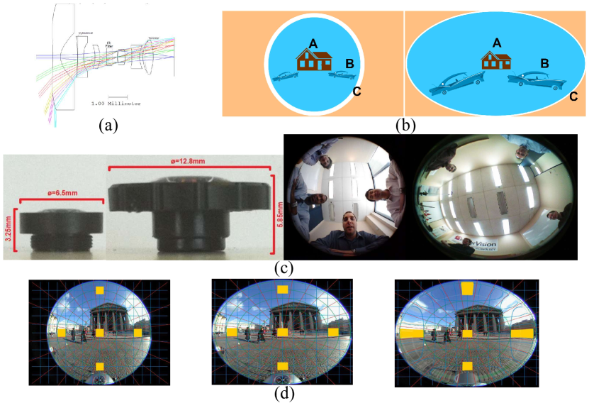
Thibault [54] proposed a novel type of panoramic camera: Panomorph lenses in 2006, and discussed the ways to control anamorphic and distortion profile. Such systems have higher sensor area usage and more pixels in the region of interest [53, 118]. The panomorph systems are usually equipped with cylindrical and toroidal surfaces to achieve different anamorphic ratios [119, 55, 120]. The optical path of this optical system is shown in Fig. 5(a), which can be used in a surveillance system to monitor driving conditions [55, 120]. As shown in Fig. 5(b), the fisheye system images the distant house A, the car B, and the edge-FoV C on the sensor. The image size distribution is shown on the left. The image taken by the panomorph system is shown in the right picture [121]. The far house A occupies a smaller area, and the car B is larger, and the edge C has a more obvious compression effect, indicating that the system has more pixels in the area of interest and is more suitable for enhanced surveillance and driving monitoring systems. The realized panomorph systems and imaging results are shown in Fig. 5(c)[55]. Fig. 5(d) shows the parking lot image, taken by a fisheye lens (Left) and a panoramic lens with equidistant projection (Middle). The yellow area is the relative size of the objects in the image. The panomorph lens provides a resolution gain by providing an anamorphic correction. The resolution on the borders is twice as high as the resolution in the center taken by a panomorph lens, also shown in Fig. 5(d)(Right)[122]. Tolerancing is the basic procedure of lens design. [123] studied and showed how the entrance pupil changes with the FoV of these optical systems (position and size), and come to the conclusion that the distortion comes from the front surface of the lens.
Surface irregularity error is usually used to specify the manufacturing accuracy of spherical-, aspherical-, or flat surfaces. A spatially correlated representation of irregular slope is proposed and implemented to specify surface accuracy in [124] and the front surface cases of fisheye and panoramic lenses are investigated in detail. In the design of modern panoramic optical systems, distortion control is particularly important. The design and distortion control of modern panoramic systems are analyzed and discussed in [125]. The optical testing of modern panoramic lenses on the market for safety and monitoring applications is reported for the first time in [126]. The first test is on the measurement of image mapping, especially on the reciprocal of Instantaneous Field of View (IFoV) expressed in pixels/degrees. The second test is to measure the MTF of the system. All tested lenses are coupled to the same camera to measure the MTF of the system. Therefore, any change in the front surface will greatly affect the image footprint. Similar image effects can be achieved by using fisheye lens image and one-directional linear interpolation algorithms [127]. To improve the relative illuminance of panomorph lenses, it is necessary to study their 3D entrance pupil mode [128]. It is shown that with the increase of FoV and pupil size, the entrance pupil moves forward, the optical axis is shifted, tilted, and deformed [129]. This increased-resolution panomorph lens is particularly suitable for use in implementing vehicle positioning and tracking [130]. [131] demonstrated that wide-angle FoV, enhanced resolution, close focusing, and distortion-free multivisualization software can improve laparoscopic and other endoscopic procedures. Furthermore, infrared panoramic lens can play a huge role in military short-distance positioning and urban security surveillance tasks [132, 119].
III-D Catadioptric Panoramic System
Catadioptric panoramic system is mainly composed of two parts, one part is the reflective optical element, and the other part is the refractive optical element [133, 134, 135, 136]. The reflective element is generally the mirror of the front element of the catadioptric system (Fig. 6(a)). The fisheye optical system uses multiple negative meniscus lenses for refraction, compressing the direction of the light entering relay lens group. Different from the fisheye optical system, the catadioptric panoramic optical system uses a mirror to reflect the surrounding light into the relay lens group. The refractive element of the catadioptric panoramic optical system is the relay lens group, which is used to correct aberrations for imaging. The mirror is placed in front of the aperture diaphragm and relay lens group. Also, the - distortion of such panoramic optical systems is usually greater than due to the large FoV for imaging [56, 57]. Compared to fisheye optics, it has fewer front lenses and focuses on surround-view imaging. Due to its characteristic as catadioptric imaging, this optical system images itself in the center of the image, which can also be considered as a blind area or area of non-interest. Due to the inaccurate localization of feature points, the distorted chessboard image will affect the accuracy of panoramic camera calibration. Distorted checkerboard images can affect the calibration accuracy of panoramic cameras due to the inaccurate positioning of feature points. Compared with the conventional approach, iterative refinement method [137] reduces the reprojection error of feature points by .
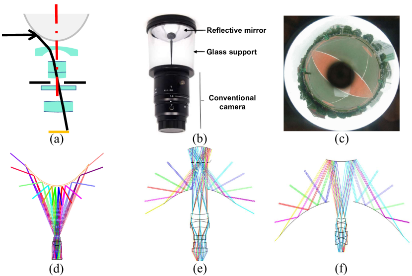
The catadioptric panoramic system is usually equipped with a transparent glass support or center mount to connect a conventional camera and a mirror, as depicted in Fig. 6(b) [138, 140]. The center of the captured image images the sensor, which is also a kind of blind area (Fig. 6(c)) [139]. A cata-fisheye camera with a FoV can be achieved by using a fisheye camera and a mirror [141]. To achieve the ideal object-image relationship, catadioptric panoramic optical systems that use a single mirror on the front element are usually designed with aspheric surfaces such as paraboloids, hyperboloids, and ellipsoids. The corresponding area of the blind area of single mirror catadioptric panoramic system is the ground, its optical path diagram is shown in Fig. 6(d). To achieve panoramic images in four directions with VGA video standard, a catadioptric panoramic system using an odd aspheric design is proposed in [142], its image distortion is less than . Over the past few decades, the technology of image sensor provides a platform for large FoV and high-resolution 3D shooting, analysis, and static- or dynamic scenes modeling [143]. For example, vision-based driver assistance can obtain real-time 3D data from mobile platforms. The use of convex mirrors and fisheye cameras can form a panoramic stereo imaging system and can adapt to non-single-view imaging conditions for 3D reconstruction in Euclidean space [144]. The concept of the catadioptric mirror can also be applied to endoscope design to simplify and reduce the volume of the system [145, 146]. The catadioptric panorama makes it possible that endoscope capsule can also use a conic mirror to observe the inner wall of the human body [147]. [148] demonstrated that a compact dual-channel endoscopic probe can simultaneously observe the needs of forward and backward FoVs in the colon. Similar designs can also be used in endoscopic capsules [149]. Developing a new convex mirror and repositioning the camera viewpoint can improve the efficiency of the catadioptric camera in the RoboCup MSL robot [150]. This design can be used not only in the visible light band but also in a wide-spectrum infrared panoramic catadioptric system [151, 152]. In the military field, infrared panoramic system is also widely used [153]. The US Navy Research laboratory has developed a high-resolution medium-wave-infrared panoramic periscope sensor system [154]. The compact system can provide horizontal azimuth and elevation FoV without moving components. The design difficulty of a catadioptric imaging system mainly lies in determining the initial structural parameters of the quadric mirror of the system. In conjunction with genetic algorithm and gradient descent, Zeng et al. [155] proposed a panoramic thermal imaging system to demonstrate the effectiveness of the method. In [156], the challenges involved in the three schemes to realize panoramic thermal imaging are discussed, and the spatial resolution, FoV, data complexity, system complexity, and cost of different solutions are analyzed in detail. The three solutions are a camera design of a long-wavelength infrared XGA sensor, the splicing of three adjacent long-wave infrared sensors equipped with a low distortion camera, and a half-FoV fisheye camera with an XGA sensor. Using a progressive design approach, Qiu et al. [157] designed a m long-wave infrared earth panorama system. Lim et al. [158] used the graphically symmetric method to correct for chromatic aberration and planar Pitzval field curvature, and designed a catadioptric system with a planar mirror. The space between the mirror surface and the relay lens group can also be changed from air to plastic [159, 160, 161, 162]. Using plastic lenses, a low-cost laser scanner for smart vehicle perception was designed in [163]. A front lens group can be set in front of the central FoV of the solid reflector to realize a catadioptric imaging system to simulate honeybee eyes [164]. The use of catadioptric optics with both forward and radial imaging channels enables minimally invasive endoscopic screening for gastrointestinal diseases, extending the detection range [165]. To significantly improve the visual authenticity of minimally invasive surgery and diagnosis in vivo, a dual-channel panoramic endoscope is proposed in [166], whose FoV is and from the optical axis. The system uses optical fiber or LED to illuminate the whole FoV. The panoramic endoscope can prevent repeated insertion of traditional endoscopes with different perspectives and reduce the risk of misleading due to the limited FoV of traditional endoscopes. Using an annularly-stitched aspherical surface, Chen et al. [167] realized a ultra-wide-angle three-channel catadioptric optical system. The research results show that the annularly-stitched asphere surface can significantly improve the imaging quality of different channels and realize the optimization of multi-channel and multi-FoVs imaging performance. In [168], a double distortion correction method for panoramic images is proposed, which solves the problem of low calibration accuracy caused by the mirror distortion of the catadioptric system. Computational ghost imaging and single-pixel imaging enable imaging and sensing under many challenging circumstances (e.g., scattering/turbulence, low temperature, unconventional spectroscopy). The ghost panoramic single-pixel imaging proposed in [169] has broad application prospects in fast-moving target localization and situational awareness for autonomous driving.
Catadioptric panoramic imaging systems using a two-mirror design have also appeared. To reduce the blind area ratio, a catadioptric panoramic system using two mirrors with the same bending direction was proposed in [68]. The system realized that the blind area is less than . Yang et al. [170] adopted a similar structure and designed a catadioptric panoramic system for imaging at m. This catadioptric panoramic architecture can be used to design low F-number long-wave infrared panorama systems [171]. The design and performance comparison of the two mirrors in the same (Fig. 6(e)) and opposite (Fig. 6(f)) directions is discussed in detail in [57]. In the field of automatic driving, the use of visible and infrared dual bands can help to realize day- and night panoramic scene detection [172].
Ultraviolet detection technology is concentrated in the nm ultraviolet band. The solar radiation in this band is strongly absorbed by the ozone layer and hardly exists in the near-earth atmosphere. It is called sun blind ultraviolet. In the solar-blind area, the ultraviolet radiation generated by targets such as flames and high-voltage discharge coronas is easily revealed under the weak radiation background noise. The ultraviolet detection technology realizes the monitoring of dangerous targets by detecting these spectral signals. The front element of the system can be constructed by using two mirrors and a transmissive meniscus lens to realize target detection in the ultraviolet spectrum [26]. Panoramic detection in both visible and ultraviolet wavelengths can be achieved by using a beam splitter [173]. Using two Charge-Coupled Device (CCD) cameras and two parabolic convex mirrors, combined with an enhancement of existing deep feature matching methods with epipolar constraints, a practical panoramic stereo sensor can be realized [174].
Further, in [175, 176], the researchers designed a mirror panoramic system composed of four mirrors. It is composed of pseudo-Cassegrain collecting mirror and a reverse pseudo-Cassegrain imaging mirror, which can image visible light and long-wave infrared light simultaneously. The FoV of the system is and the F-number is .
III-E Monocentric Panoramic System
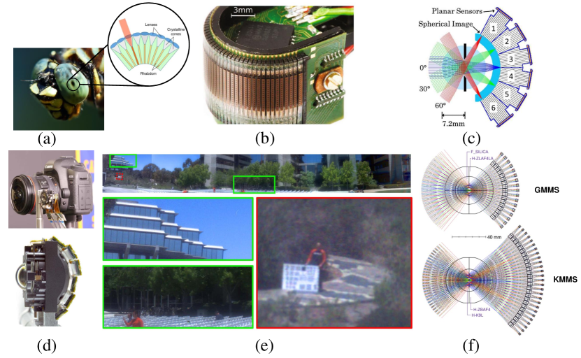
Compound eye (Fig. 7(a)) [177, 180, 181, 182, 183, 184, 185, 186] is a typical feature of arthropod in nature. Compared with a single aperture vision system, the compound eye possesses many excellent imaging characteristics, such as compact size, wide FoV, great perception of moving objects and sensitivity to light intensity [187]. Benefiting from the development of electronic sensors and advances in micro-nano fabrication, the realization of curved sensors makes traditional optical systems no longer limited to imaging on flat sensors. In 2014, Viollet et al. [178] proposed a Curved Artificial Compound Eye (CurvACE) (Fig. 7(b)) inspired by drosophila. It is composed of a microlens array, a neuromorphic photodetector array, and a flexible Printed Circuie Board (PCB). It consists of ommatidia and CurvACE’s FoV is . To satisfy the requirements of miniaturization, high imaging quality, large FoV of monitoring camera, and the development of curved image sensor, Wang et al. [61] designed a monocentric monitoring lens optical system. The monocentric system has a FoV of , mm focal length, mm total length, and F/. A monocentric lens with multi-aperture integration was proposed (Fig. 7(c))[179] in 2015. This optical system has the characteristics of all optical surfaces are spherical and share a common center of curvature. The monocentric lens with compact imager volume has no coma or astigmatic aberration. A F/, megapixels, fiber-coupled monocentric lens imager prototype greatly reduces the volume of the wide-FoV imaging system compared to a commercial F/ camera (Fig. 7(d)) [179]. The image processing methodology can significantly improve the quality of the fiber relayed prototype image, as illustrated in Fig. 7(e) [179]. A gigapixel monocentric multiscale imager has been shown to integrate a two-dimensional mosaic of subimages [59, 188, 189]. This wide- and uniform field can also be realized by waveguide method [190]. Instead of relay optics, one or more multimode fiber bundles [191, 192] can be used to transfer the spherical image surface to a conventional planar image sensor. To help determine the best specific design for a 4GA-8 lens, a wide FoV monocentric lens is studied from simple structures to moderately complex in [193], and a system optimization method for global optimization of dual-glass lenses are proposed for a series of large FoV imaging systems to offer practical high-performance options. The monocentric lens has recently shifted from the initial historical curiosity [194] to a promising approach for panoramic high-resolution imagers. In [195, 196], the technique of monocentric lens using analytical aberration calculation and constrained numerical optimization was introduced, and its application in fully symmetric and hemispherical symmetric lenses was demonstrated. The performance summary of the monocentric lenses in the visible and near-infrared spectral bands can be used to guide the design of various monocentric lenses. [197] established the potential of a fiber-coupled monocentric imager in the novel panoramic high-resolution imaging and verified the ability of the monocentric lens to focus large FoV images at a series of object depths. By changing the fiber bundle structure can improve spatial resolution. Thanks to digital image processing, imaging quality can be further enhanced. In [60], the visible light and visible near-infrared spectrum monocentric system which transmits the curved image to the Complementary Metal Oxide Semiconductor (CMOS) focal plane through the fiber bundle to generate the high-resolution panoramic image was described. By eliminating the overlapping requirements of adjacent sub-images, the monocentric multi-scale system volume was reduced and the relative illumination and imaging quality were improved [198]. Compared with the previous first generation of monocentric multi-scale gigabit pixel cameras with Keplerian design, the total volume of Galilean monocentric multi-scale system can be reduced by times. In [199], a novel architecture was defined for near monocentric imaging. The folding architecture provides a more miniaturized structure, especially when the structure includes auxiliary folding mirrors. In [200], researchers applied computational imaging theory to optical system design and developed a geometric aberration optimization function, which avoids using repeated iteration of optical system to define initial value of required system. It helped to improve the time efficiency of the system design. This design not only solved the contradiction between wide FoV and high resolution but also provided a new design idea for computational imaging. A new analytical model of Galileo Monocentric Multi-Scale (GMMS) and Keplerian Monocentric Multi-Scale (KMMS) was proposed in [58], which is more accurate than the paraxial form. The model avoids the laborious analysis of different monocentric lens forms and maintains the key points of the Monocentric Multi-Scale (MMS) system. In addition, the correlation between GMMS and KMMS system design parameters was discussed in detail. The results showed that the GMMS system behaves better in aberration performance. The research provided a useful reference for the further application and development of monocentric lens system. The light field camera can still focus accurately and take clear photos under the condition of low-light and high-speed image movement. The concept of monocentric panoramic light field is proposed by combining a monocentric lens and light field sensors in [201]. The latest research showed that the system using the combination of monocentric lens and microlens array can significantly improve the imaging quality and light field reconstruction using the calculated point spread function model [202].
III-F Hyper-hemispheric Lens
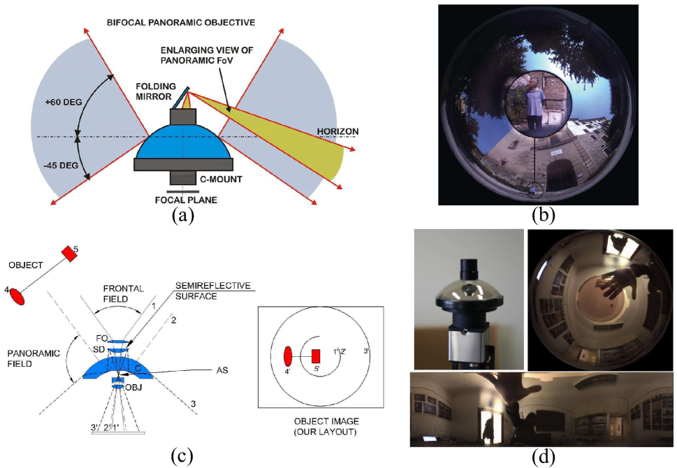
The FoV of a common panoramic camera is greater than . To realize super-large FoV imaging, a hyper-hemispheric lens [63] was proposed by Pernechele. The FoV angle of this ultra-wide-angle system is . A kind of bifocal hyper-hemispheric lens was mentioned in [62, 203]. The system layout of this hyper-hemispheric lens is shown in Fig. 8(a) and its unwrapped image is shown in Fig. 8(b). The panoramic channel uses a meniscus lens to collect and image of the surrounding light. There is a blind area in the center of the system. To avoid the waste of the imaging area of the sensor in the central blind area, the front lens group and the mirror can be used for imaging, and the imaging area can be regarded as the area of interest. The entire system has two focal lengths for the front channel and the panoramic channel. Using an even aspheric surface, Gong et al. [204] used a similar structure to design a panoramic imaging system with a full FoV of without blind area. Another design concept of the dual-channel panoramic system was mentioned in [63]. By coating semi-reflective film, continuous imaging of front FoV and panoramic FoV can be realized. As shown in Fig. 8(c), the oval and square red targets and their connecting lines can form a continuous image in the image plane of the sensor. In [62, 64], a hyper-hemispheric lens (Fig. 8(d)) is capable of imaging the FoV with an azimuth angle of and a zenithal angle of was proposed. In this study, the theoretical optical quality, projection, and angular resolution of the hyper-hemispheric lens with a paraxial focal length of mm were discussed and analyzed in detail. The example pictures of the displayed hyper-hemispheric image proved that the design can successfully obtain the panoramic image with a ultra large FoV. The hyper-hemispheric lens can also be used as a multi-purpose panoramic camera for a star tracker to capture images. The attitude determination algorithm of space platform was proposed in [205]. The most advanced star tracker can accurately image as many stars as possible in a narrow- or moderate FoV, but its observation ability is limited by the FoV characteristics of the optical system. By combining algorithmic concepts from the fields of computer vision and robotics researches, such as template matching and point cloud registration, the method was used for star recognition. The system provides a stable and trustworthy initial attitude approach for space platforms such as satellites. It can estimate the attitude with an accuracy better than and evaluate the success rate of about .
III-G Panoramic Annular Lens
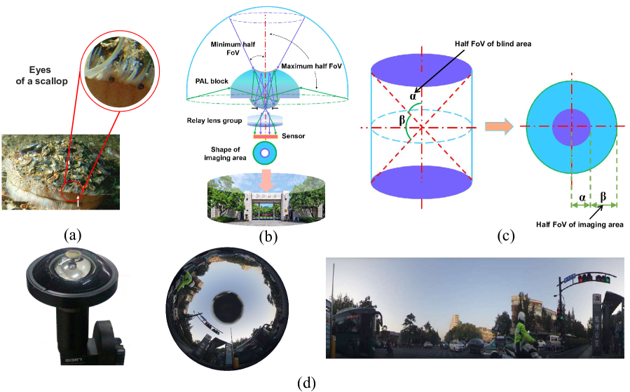
Nature provides a steady stream of inspiration for human innovations in bionic optics. In nature, a scallop usually possesses a visual system comprising up to 200 eyes that allow them to observe the surroundings through slits in the shell (Fig. 9(a))[206]. Each eye of the Pecten scallop consists of a highly unusual double-layered retina, a cornea, a weakly refractive lens, and a concave mirror. Inspired by the distinctive imaging light path of refraction and reflection in the Pecten scallop eye[208], panoramic annular lens was first formally proposed by Greguss in 1986 [209]. The whole system is mainly composed of three parts: a panoramic annular lens block, a relay lens group and a sensor, as shown in Fig. 9(b). Different from the traditional fisheye lens that refracts ambient light through multiple lenses to form a panoramic image (Fig. 2), the panoramic annular lens is equipped with a catadioptric panoramic annular lens block to replace the lens group in the front of the fisheye lens. This catadioptric structure makes the panoramic annular lens more compact than the fisheye optical system. The ambient light around the panoramic annular system is converted into a small-angle beam after two refractions and two reflections in the panoramic annular lens block during imaging. The small-angle beam is imaged on the sensor after passing through the aperture diaphragm and the relay lens group to form a two-dimensional annular panoramic image. According to the flat cylinder projection principle (Fig. 9(c)), the system can form a annular image with a half-FoV , so it is called a panoramic annular lens. Due to the occlusion of the small mirror in the front part of the panoramic annular lens block, a blind area of the half-FoV will be formed in the center of the FoV.
Afterwards, Powell studied and designed the infrared panoramic annular system [210, 27]. The prototype, raw image, and unwrapped image of the panoramic annular imaging system are shown in Fig. 9(d), which can realize high-definition panoramic imaging [207]. Using a multilayer diffractive optical element, Niu et al. [72] realized a long-focal-length panoramic annular system with an effective focal length of mm and a diffraction efficiency greater than . The designed panoramic annular system can be used to monitor cavity pipes, water wells, and mines, detect and record the rapid process of the rocket launch and explosion, spacecraft orientation, navigation system, and many other spaces that need to be measured [211]. Binocular stereo panoramic imaging can obtain and measure depth information [212]. Stray light will seriously affect the imaging quality in the panoramic optical system. The analysis and suppression of stray light in the optimization design can eliminate the influence of stray light and ensure that the captured image can still have good imaging ability in the face of strong light sources such as the sun [213]. [214] proposed new unwrapped and distortion correction methods to extract information from panoramic shots. The concept of using a panoramic annular lens as an endoscope was first proposed in 1991 [215, 216]. It is proven that this ultra-wide-angle optical system can also be used in holographic interferometry [217]. For a variety of use scenarios, [218] described the design details of a panoramic annular monitoring system, a deformation monitoring system, a mobile camera with panoramic annular accessories, and a panoramic annular endoscope system. [219] presented a panoramic endoscope imaging system based on the freeform surface. The front channel of the system uses a steering mirror, so that the front channel can enlarge the local details of the panoramic channel. Compared with the traditional wide FoV endoscope, this design does not need to rotate and uses the dual-channel FoV to realize panoramic observation and local magnification, which can reduce the diagnosis time and improve the lesion detection rate. In 2015, Wang et al. [74] applied ogive surface to the design of panoramic annular lens for the first time and obtained a panoramic annular system with an effective focal length of mm.
To obtain more visual field information while keeping the system compact, Huang et al. [78] proposed an even ogive surface and a compact dual-channel panoramic optical system with FoVs of and in 2017. In 2020, a kind of ogive panoramic annular lens was fabricated [65]. It realized the ultra-low distortion design with a FoV of and - distortion less than . This ultra-low distortion design is especially suitable for computer vision tasks such as Simultaneous Localization and Mapping (SLAM) [85]. In terms of light field display, the pure horizontal parallax light field display of a panoramic camera was adopted to determine that it can provide smooth and continuous full parallax presentation for multiple viewers within panoramic FoV [220]. Q_bfs aspheres can significantly reduce distortion in the design of panoramic annular lens [221, 222].
Star tracker plays an essential role in satellite navigation. Star trackers on satellites in low earth orbit usually have two optical systems: one is to observe the contour of the earth and the other is to capture the position of stars. In [219], a star tracker optical observation system with a dual-channel panoramic annular system based on a dichroic filter was shown. It can observe the earth with a panoramic FoV range of nm band of , and the front channel can capture stars far away from the system with a FoV range of nm band of . In the aerospace field, the panoramic annular lens can be used to expand the FoV of astronauts in performing extravehicular activity [223]. The study [224] showed that the conic conformal dome of the aircraft has no obvious impact on the panoramic annular lens, and can even improve the imaging quality. It indicates that the panoramic annular lens is also suitable to be equipped in an optical window with conic conformal dome. The dual-channel panoramic annular lens structure can be used as an atmospheric detection optical system [225]. Compared with the traditional optical system, the optical system can observe the sky bottom view and panoramic side view at the same time, which improves the efficiency and accuracy of observation data inversion. The imaging spectrometer of traditional atmospheric detection usually uses a prism or grating to split the beam, and can only explore the atmosphere through single-mode single detection. Using the electronic filter developed based on the crystal acoustooptic effect, a novel panoramic imaging spectrometer [226] for atmospheric detection was designed. It can detect the hyperspectral atmospheric data of nadir FoV, limb FoV, and km limb height.
The use of binary diffractive surfaces in the design process of the panoramic annular lens is beneficial for improving the imaging effect and simplifying the optical structure [227]. To realize the design of super large FoV without a blind area, Wang et al. [228] proposed a dual-channel panoramic system without a blind area. The FoV of the whole system is . The FoV of the front channel is , and the FoV of the panoramic channel is . More optimization parameters can be obtained by using even aspheric surfaces, and the imaging performance of a larger FoV can be improved [229].
With the rapid development of sensor technology and the emergence of polarization sensor [230], panoramic perception is no longer limited to visible and infrared bands. Polarization sensing can make the traditional panoramic optical system obtain higher dimensional information and realize panoramic multidimensional sensing. An effective way to detect pavement conditions is to use polarization characteristics. The use of a panoramic annular camera and a polarization filter can capture vertical and horizontal polarization images at the same time without camera calibration [231]. The low spatial resolution of elevation angle of panoramic annular image in the vertical direction will lead to quality degradation of unfolded panoramic image. Using multiple panoramic annular lens images can generate high quality panoramic images, which can effectively solve this drawback [232, 233, 234]. Using the particle filter can detect and track the target in panoramic image with high precision [235]. The multimodal vision sensor fusion technology [236] used a polarization camera, a stereo camera, and a panoramic annular lens to realize multidimensional environment perception for autonomous driving.
With the development of information technology (such as 5G and 6G), the high-resolution panoramic annular system [15] can record and transmit more panoramic information data in real-time. With the continuous deepening of the panoramic annular system, researchers have begun to focus on the realization of panoramic detection of different FoVs. The ultimate goal is to achieve search in a large FoV and accurate target observation and detection in a small FoV. By optimizing the azimuth characteristics of the panoramic annular lens, a two-channel panoramic annular system with double focal lengths was proposed in [237]. One of the channels has a smaller focal length and a wider-FoV coarse search channel and the other longer focal length and smaller-FoV channel is called the fine observation channel. Using XY polynomials freeform surface, Ma et al. [76] proposed a new zoom mechanism to achieve a panoramic zoom that does not deviate from the center of the FoV of the observation target. Afterwards, Wang et al. [77] proposed a zoom panorama optical system designed by a mechanical zoom method, which achieved a focal length change of mm and a maximum half FoV ranging from to . The common zoom panoramic annular lens is based on the axial displacement between optical lens groups, which will enlarge the blind area. The zoom panoramic annular lens proposed in [238] is based on the Alvarez freedom surface of transverse displacement, which can enlarge the imaging area and keep the blind area unchanged. To improve design freedom degree and correct the color difference, Liu et al. [79] used a three-cemented panoramic annular block to design a panoramic annular lens with FoVs of and , respectively. To design a new freeform surface panoramic system, using the YOZ plane-symmetric extended polynomial freeform surface, Bian et al. [239] offered a rectangular image field panoramic system with a FoV of . Using annularly-stitched aspheres technology, Chen et al. [240, 241] demonstrated a dual-view endoscope without blind area. The FoV of the front channel is , and the FoV of the panoramic channel is . The blind area of the panoramic annular lens reduces the sensor utilization. To solve this problem, Luo et al. proposed the methods of dichroic filter [80] and polarizing film [43] to eliminate the center blind area. To achieve a high-resolution panoramic system while maintaining a compact structure, [66] proposed a ray-tracing theory on the influence between the entrance pupil diameter and panoramic annular block parameters and successfully presented a high-resolution panoramic system with a compact ratio of without blind area. There is no vignetting in the system and two channels share the relay lens group with the same parameters. To achieve a more compact and lightweight design, a panoramic annular system based on focal power distribution theory with Petzval sum correction was presented in [16]. The whole system with only three spherical lenses achieves a large FoV of , and the enhancement of the panoramic image based on PAL-Restormer enables higher performance in various computer vision tasks.
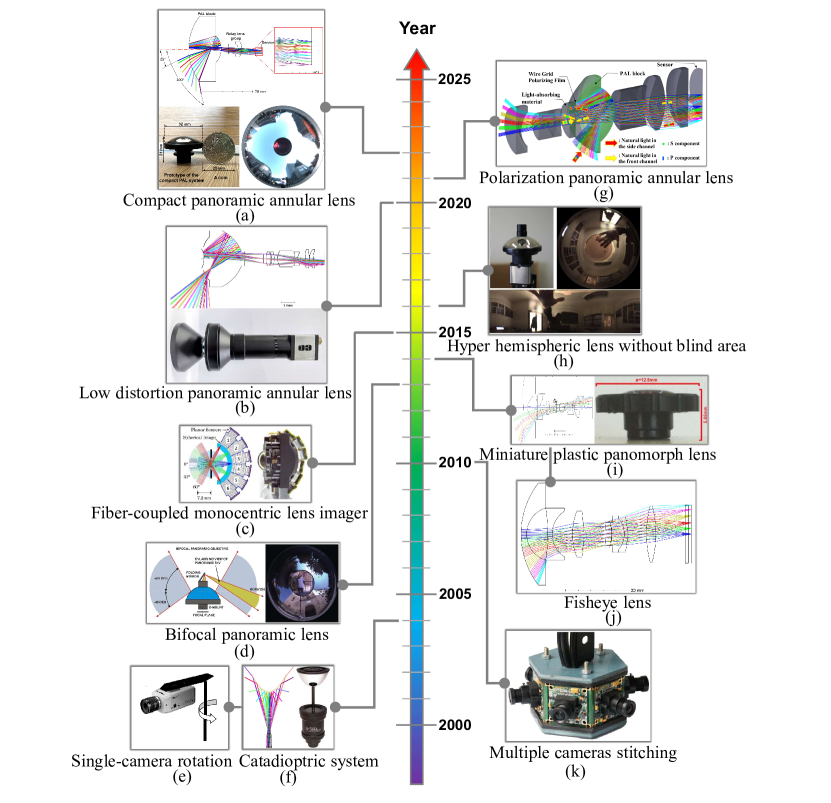
To more clearly describe the vigorous progress of panoramic imaging systems in the last 20 years, the history of panoramic development and the comparison of key parameters of different panoramic imaging architectures are summarized in Fig. 10 and Table II, respectively.
| System category | Year | Author | Key parameters | ||||
| FoV | Wavelength | F-number | Focal length | Resolution/Format | |||
| Single-camera rotation | 2003 | Gledhill et al. [1] | Visible | N/A | N/A | ||
| Multiple cameras stitching | 2010 | Yuan et al. [47] | (6 cameras) | Visible | N/A | N/A | N/A |
| 2014 | Huang et al. [89] | (4 cameras) | Visible | N/A | N/A | N/A | |
| 2019 | Cowan et al. [48] | (9 cameras) | IR | 1.1 | 1.4 mm | ||
| Fisheye panoramic system | 2015 | Samy et al. [105] | 400700 nm | 2.8 | 1 mm | 1/3.2 inch | |
| 2017 | Geng et al. [114] | 480650 nm | 5 | 5 mm | |||
| 2018 | Song et al. [113] | 2 | 423660 nm | 2 | 1.43 mm | ||
| 2019 | Hwang et al. [44] | Visible | N/A | N/A | N/A | ||
| 2020 | Song et al. [111] | 2 | 423660 nm | 1.8 | Afocal lens | > | |
| 2021 | Pernechele et al. [71] | 500770 nm | 3 | 3.3 mm | |||
| Panomorph imaging system | 2006 | Thibault [54] | 400700 nm | 1.9 | 1.15/0.9 mm | ||
| 2014 | Thibault et al. [55] | 400700 nm | 2.8 | N/A | |||
| 2014 | Thibault et al. [55] | 400700 nm | 2.8 | N/A | |||
| Catadioptric panoramic system | 2006 | Kweon et al. [142] | Visible | 5.53 | 24.8 mm | ||
| 2015 | Sheu et al. [149] | Visible | 3.5 | 0.76,1.23mm | |||
| 2016 | Cheng et al. [167] | 486656 nm | 2.5 | 1 mm | 1.3 Mega,1/2.56 inch | ||
| 2019 | Zhuang et al. [56] | 480650 nm | 2.3 | 0.5 mm | |||
| 2019 | Wu et al. [57] | 812 m | 1.2 | N/A | |||
| 2019 | Wu et al. [57] | 812 m | 1.2 | N/A | |||
| 2020 | Zhang et al. [68] | 486656 nm | 4 | 2 mm | N/A | ||
| Monocentric panoramic system | 2012 | Stamenov et al. [190] | Visible | 1.7 | 12 mm | N/A | |
| 2013 | Stamenov et al. [193] | 380550 nm | 1.79 | 12 mm | N/A | ||
| 2013 | Stamenov et al. [193] | 500900 nm | 1.2 | 16 mm | N/A | ||
| 2013 | Stamenov et al. [193] | 9001500 nm | 1.19 | 12 mm | |||
| 2013 | Stamenov et al. [193] | 486656 nm | 2.33 | 112 mm | N/A | ||
| 2013 | Stamenov et al. [193] | 450700 nm | 2.8 | 280 mm | N/A | ||
| 2019 | Wang et al. [61] | 486656 nm | 1.5 | 7.88 mm | 11 Mega | ||
| Hyper-hemispheric lens | 2013 | Pernechele [63, 62] | 500650 nm | 3.5 | 6,2mm | 2/3 inch | |
| 2016 | Pernechele [64, 62] | 500650 nm | 3.5 | 2 mm | 2/3 inch | ||
| Panoramic annular lens | 1994 | Powell [210] | 35 m | 1.5 | 2.65 mm | ||
| 2007 | Niu et al. [72] | 486656 nm | 3.7 | 10.8 mm | |||
| 2011 | Wang et al. [26] | 245285 nm | 2 | N/A | N/A | ||
| 2012 | Hui et al. [218] | 486656 nm | 2 | 0.96 mm | 1/3 inch | ||
| 2012 | Hui et al. [218] | Visible | 2.8 | 0.82 mm | 5 Mega | ||
| 2012 | Hui et al. [218] | Visible | 2 | 0.27 mm | N/A | ||
| 2012 | Huang et al. [212] | 486656 nm | 3.18,3.22 | 3.19 mm | |||
| 2014 | Xue et al. [75] | 355365 nm | 3.3 | 5 mm | |||
| 2015 | Wang et al. [74] | 486656 nm | N/A | 10.375 mm | N/A | ||
| 2016 | Liu et al. [219] | 486656 nm | 2.65,2.8 | 2.12,0.82mm | |||
| 2016 | Yao et al. [73] | 812 m | 1.15 | 3.4 mm | |||
| 2016 | Zhou et al. [222] | 486656 nm | 3.8 | 0.86 mm | 1/3 inch | ||
| 2017 | Huang et al. [78] | 486656 nm | 5 | 2.75,3.12 mm | N/A | ||
| 2017 | Luo et al. [43] | 486656 nm | 3.3,3.0 | 0.833,0.895mm | |||
| 2019 | Wang et al. [226] | 450800 nm | 6.5 | 7.5,4mm | N/A | ||
| 2019 | Wang et al. [228] | 486656 nm | 5 | 3,5mm | |||
| 2019 | Chen et al. [240] | 486656 nm | 3.4 | 0.83,1.17mm | |||
| 2019 | Wang et al. [15] | 486656 nm | 3.98 | 4.47 mm | |||
| 2020 | Amani et al. [229] | 486656 nm | 5 | 0.417,0.433mm | |||
| 2020 | Zhou et al. [65] | 486656 nm | 4.5 | 4.34 mm | |||
| 2021 | Gao et al. [66] | 486656 nm | 2.5 | 0.8,1.55mm | |||
| 2021 | Wang et al. [77] | 486656 nm | 4.226.51 | 3.86mm | N/A | ||
| 2021 | Wang et al. [67] | 486656 nm | 4.7 | 3.86 mm | |||
| 2022 | Wang et al. [243] | 486656 nm | 3.97,2.98 | 1.27,4.48mm | |||
| 2022 | Gao et al. [16] | 486656 nm | 5.5 | 1.17 mm | |||
IV New Engines of Panoramic Optical Systems
IV-A Freeform Surface
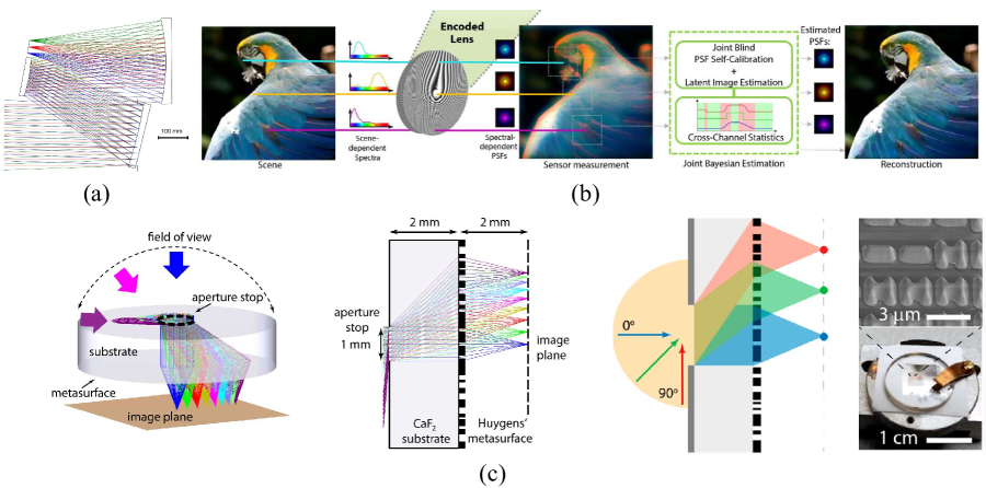
With the continuous development of advanced manufacturing technology and testing technology, freeform optical elements make it possible for compact and high-image-quality imaging optical systems [244, 245, 82, 246]. Optical freeform surfaces in imaging optical design generally refer to optical surfaces that do not have axis-rotational symmetry or translation-rotational symmetry [247, 248, 249, 82]. Compared with the traditional spherical surface, the freeform surface can provide more degrees of freedom, significantly improve the optical performance of the imaging system, and reduce the volume of the system [250] (Fig. 11(a)). This technology has significantly promoted applications from science to a wide range of fields, such as extreme ultraviolet lithography and space optics [13]. Freeform optics is a concurrent engineering process that combines design, manufacturing, testing, and assembly. The continuous development of freeform optics has important significance and value for the whole human society to perceive the panoramic environment.
The traditional panoramic lens design uses spherical lens. To improve the freedom of optical designers in designing the panoramic system, the use of rotationally symmetric aspheric surfaces can give panoramic imaging systems a new opportunity. Thanks to the multi-degree of freedom design parameters of the aspheric surface, the panoramic imaging system can realize the system parameters, structure, and functions that are difficult to be realized in traditional panoramic systems. The proposed odd aspheric surface [142], even aspheric surface [229], Q-type aspheric surface [252, 253, 254], extended polynomial aspheric surface [239], annularly-stitched aspheric surface [255, 167], ogive aspheric surface [74, 65], and even ogive aspheric surface [78] have been proved to be successfully applied to the design of panoramic systems. The asymmetric freeform surface also makes the panoramic optical system have a new zoom function, including Alvarez surface freeform surface [238] and XY polynomial aspheric surface [76]. In the future, we believe that the new freeform surface technology can make panoramic imaging optical systems obtain more exciting new functions, high imaging quality, compact volume, and so on.
Although freeform surfaces have revolutionized the field of optical design in the last decade, there are still some challenges and some directions to be explored in this technology [82]. In the design area, more powerful global optimization algorithms need to be explored to achieve fast, accurate, and generalized direct point-by-point algorithms. In terms of applications, there is an urgent need to further improve the accuracy and efficiency of freeform surfaces for fabrication, testing, and assembly. In conclusion, the freeform technology has much potential for exploration and research, and is a powerful engine for the development of panoramic imaging technology.
IV-B Thin-plate Optics
Thin-plate optics is a new imaging approach that uses Fresnel optics or diffractive optics or other optical elements to design thin-plate lenses that are combined with computational imaging techniques to recover or enhance images [83]. This technique allows the use of lightweight optical elements to build a compact optical system with the same or better image quality than conventional bulky imaging system. The thin-plate optical technology will facilitate the lightweight and miniaturization of the panoramic imaging system.
Different from traditional optical imaging, computational imaging technology [256, 257, 258] can encode and decode optical information captured by optical instruments in all directions from information acquisition, information transmission, and information conversion in terms of imaging principles. Computational imaging can acquire and analyze multidimensional information of the light field through scattering, polarization, and bionic technologies, and has many advantages in achieving large detection distance, high resolution [259, 260], high signal-to-noise ratio, multidimensional information [261], light weight[262], simplicity, and cheapness. For decades, optics researchers have been working to design compact optical systems with large FoV and light weight [263, 264]. A Fresnel lens [265] is an optical element that reduces the thickness of the lens while maintaining the shape of the lens curvature and can be used as a lightweight alternative to traditional continuous surface lenses. Due to its ability to reduce the thickness of the optical system, it is widely used in non-imaging fields such as illumination, solar concentrators, and collimators. When the processing of the optical lens surface is close to the light wavelength of the imaging band, the transmission of light will no longer conform to the three transmission laws of geometric optics (straight propagation, refraction, and reflection), and a diffraction effect will occur. At this time, the optical element is called diffractive optical elements. An optical system designed with diffractive elements needs to ensure that the entire optical system has a high diffraction efficiency. Combining computational imaging technology and Fresnel/diffractive optical elements, thin-plate optics technology came into being [83]. Using diffraction-coded lens to form significantly different point spread functions for different spectral distributions, joint computational imaging technology can achieve effective phase difference recovery and image reconstruction [251] (Fig. 11(b)). With computational imaging technology, lightweight optical systems with large FoVs using Fresnel lenses or diffractive optical elements can achieve imaging quality close to that of traditional complex optical systems, enabling simple systems perception of large FoVs [266]. This next-generation imaging optical system using Fresnel or Refractive-Diffractive hybrid and computational imaging can be used to build the future of computational imaging for thin- and lightweight panoramic imaging.
With the continuous development of optical micro-nano processing technology, the processing of thin-plate optical technology has gradually matured, but there are still some challenges to be solved. In terms of principle, diffractive optical elements need to be combined with new design algorithms to improve the numerical stability and convergence speed of the design results [267]. In terms of performance, the diffraction efficiency needs to be improved and the wavelength range needs to be further expanded. In terms of applications, the exploration of thin-plate optical technology in the field of computational imaging will be more far-reaching, expanding the direction of new panoramic intelligent perception.
IV-C Wide-FoV Metalens
At present, with the rapid development of optical technology and manufacturing technology, the miniaturization of optical systems has become a focus of researches. For scene perception, wearable devices, medical devices, aerial photography, and other fields, miniaturized optical systems are favored [268, 269, 187, 270, 271, 272]. The miniaturization design of traditional optical system checks and balances with high resolution, high imaging quality, and processability, which has great design challenges and processing difficulties. As a new micro-nano surface technology, metasurface has shown great potential and the ability to overcome the physical limitations of traditional optical lenses [273, 274]. The metasurface is a kind of two-dimensional metamaterial [275]. Metamaterials are generally composed of subwavelength metal or dielectric units, which show electromagnetic characteristics different from existing materials in nature, such as negative refraction, optical stealth, and so on [276, 277, 278]. Traditional optical lenses accumulate optical path through the change of thickness and produce phase gradient, to realize the regulation of the wavefront. When light hits a subwavelength scatterer, its phase will undergo a sudden change, that is, a discontinuous change. By arranging this scatterer into a surface, and then precisely controlling the structure of each unit to control the phase of the light, it is possible to make the light converges to a point [279, 81]. This is called a metalens. Compared with the traditional optical lens, the metalens has ultra-thin size and weight. The beam can be focused to the diffraction limit and has an ultra-short focal length [280, 281]. It has broad application prospects in the visible light band, terahertz band, microwave band, and so on [282, 283, 284, 285, 286].
To realize large FoV [287, 84, 288, 14, 289] (Fig. 11(c)), achromatic [290, 291, 292, 293], broadband [294, 295], high spectral resolution [296] and other characteristics of metalenses, researchers have carried out a series of in-depth studies on metalenses, and several representative works are shown in Table III [268]. As an ultrathin optical components [297], metalens technology provides a new design idea for the panoramic system, and the commercial panoramic imaging system with small volume and high performance will become possible.
Metalens has great potential and value in miniaturized imaging, but there are still some challenges [298, 299]. In terms of design, the chromatic aberration of the metalens needs to be solved, so the metalens with broad spectrum would still a research hotspot in the future. The focusing efficiency of metalens still needs to be improved [300]. In the overall optimization of meta-based imaging systems, it is still difficult to achieve efficient loop data transfer and iteration without the help of custom codes.
In terms of fabrication, the diameter size of metalens needs to be increased in order to integrate into conventional optical systems to realize novel optical systems. In the future, panoramic imaging instruments with hyper-hemispheric FoV can be realized by combining conventional optics and metalens technology to achieve higher-performance miniature panoramic scene perception.
| Reference (Year) | Focusing efficiency (%) | Wavelength (nm) | Numerical aperture | Number of metasurface layers | Diffraction-limited FoV (∘) |
|---|---|---|---|---|---|
| Arbabi et al.(2016) [287] | 45-70 | 850 | 0.49 | 2 | 56 |
| Groever et al.(2017) [301] | 30-50 | 470-660 | 0.44 | 2 | 50 |
| Jang et al.(2018) [302] | N/A | 532 | 0.5 | 1 | 8 mm FoV |
| Guo et al.(2018) [303] | 93 | Far-field power | 0.89 | 2 | 120 |
| Xu et al.(2018) [304] | 95 | 532 | N/A | 1 | 160 |
| Engelberg et al.(2019) [305] | 6-20 | 825 | 0.2 | 1 | 30 |
| Shalaginov et al.(2020) [14] | 32-45 | 5200 | 0.24 | 1 | 170 |
| Shalaginov et al.(2020) [14] | 41-88 | 940 | 0.2 | 1 | 180 |
V Applications of Panoramic Imaging Systems
Thanks to the ultra-wide FoV offered by panoramic cameras, they have been applied in many scene understanding tasks [236]. In the following subsections, we review the applications with panoramic image systems, for robotics applications like robot navigation and autonomous driving.
V-A Semantic Scene Understanding with Image Segmentation
Semantic scene perception is an essential task in robotics, as it enables a dense understanding at the pixel level, where the location and category information can be both precisely extracted, offering abundant cues for upper-level navigation operations. Semantic scene understanding is usually achieved via semantic image segmentation. When working with panoramic cameras, a holistic and comprehensive scene segmentation can be attained for an entire surrounding perception [306], as shown in Fig. 12.
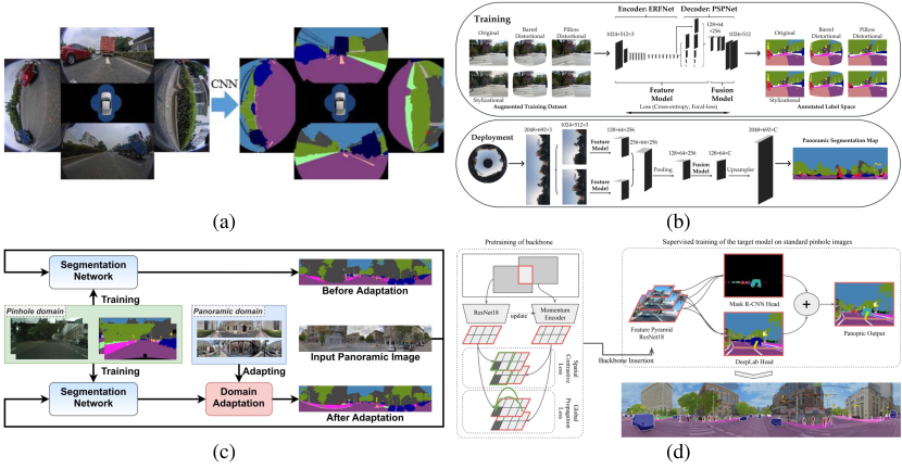
Fisheye camera based semantic segmentation. Thanks to the breakthrough of Fully Convolutional Networks (FCNs) [312], semantic segmentation can be performed in an end-to-end fashion and the field has been significantly advanced with diverse segmentation model architecture- and dataset developments. In the wide-FoV semantic segmentation, fisheye- and panoramic cameras have been applied. Yet, current deep segmentation models are data-driven, and most existing semantic segmentation datasets are established for pinhole, narrow-FoV, distortion-free images. To train an accurate and robust semantic segmentation model that can generalize well in real-world scenes, large-scale annotated datasets are important. Annotating semantic labels at the pixel level is extremely labor-intensive and time-consuming, in particular for panoramic images as they have larger distortions, higher complexities due to the wide-FoV, and more small objects in general. Thereby, most wide-FoV semantic segmentation research works have to deal with the data scarcity issue, aiming to produce robust real-world surrounding parsing models, which are vital for reliable scene understanding. Deng et al. [307] first presented a fisheye image semantic segmentation framework (Fig. 12(a)), which transforms an existing pinhole urban scene segmentation dataset to a synthetic dataset for training and designs an overlapping pyramid pooling based segmentation module to explore both local, global, and region context information. In particular, the transformation is based on a zoom augmentation method by changing the focal length of the simulated fisheye camera. They further built a surround-view surrounding road scene segmentation system by using four fisheye cameras and a deformable-convolution-based multi-task learning regimen [308], involving real-world and transformed surround-view images for training. Extending the zoom transformation method, Ye et al. [313] designed an online seven-DoF augmentation method, to synthesize fisheye images captured via sensors of different shooting orientations, postures, and focal lengths, improving the robustness against different distorted fisheye image data.
Panoramic camera based semantic segmentation. For panoramic surrounding perception based on a single camera, Yang et al. [207] designed a Panoramic Annular Semantic Segmentation (PASS) framework (Fig. 12(b)) by using a panoramic annular camera with an entire FoV of . Considering that the distortion in such cameras are lowered in less than [222] and the imaging model complies with a clear - law, the PASS framework reused large-scale pinhole data for training with a network adaptation method that exploits the correspondence between convolutional features learned from pinhole data and features inferred from panorama segments with a similar FoV. They achieved seamless semantic segmentation results by using ring-padding and cross-segment padding, together with a variety of data augmentation methods including texture-, geometric-, distortion-, and style augmentation to robustify panoramic segmentation. DS-PASS [314] improves PASS by using a more efficient segmentation model and augmenting the detail sensitivity via attention connections between detail-preserved low-level shallow encoder layers and semantic-rich high-level deep decoder layers. They have deployed the framework on both mobile robotics and instrumented vehicles with a lightweight panoramic annular camera with a FoV of , and verified the benefits of surrounding semantic sensing for upper-level navigation applications like visual odometry. Further, multi-source omni-supervised learning was leveraged in [315] to cover panoramic data in the training stage. This helps to reach robust segmentation performance, meanwhile bypassing complex panorama separation and network adaptation used in PASS [207] which incurs high computation overhead and cannot make use of the important global context cues as the panorama is divided into discrete segments. The omni-supervised learning framework was extended by learning spatial positional priors [316] and omni-range contextual dependencies [317] that can stretch across the entire . Panoramic semantic segmentation has also been applied with unmanned aerial vehicles in [318, 67] for drone-perspective panoramic remote sensing with a FoV of .
Panoramic segmentation from an adaptation perspective. More recently, to address the dearth of annotated panoramic images, researchers have explicitly formalized panoramic segmentation as an unsupervised domain adaptation problem or a domain generalization problem by transferring from the data-rich pinhole domain to the data-scarce panoramic domain [309, 311]. For domain adaptation, one can use labeled pinhole data as the source domain and unlabeled panoramic images as the target domain. For domain generalization, one can only use the source domain images, with the aim to produce a robust, generalized segmentation model in the target domain. P2PDA [309, 310] (Fig. 12(c)) designed attention-augmented domain adaptation modules to detect and magnify the pinhole-panoramic correspondences in multiple spaces. Jaus et al. [311, 319] introduced panoramic panoptic segmentation, which extended panoramic semantic segmentation by also offering instance-level understanding (Fig. 12(d)). It outputs both pixel-level semantic classes and instance IDs, and thereby enabling a more holistic surrounding perception. By appending a dense contrastive pretraining stage, they obtained significant generalization gains when segmenting unseen panoramic images. Panoramic panoptic video segmentation is also addressed with the Waymo open dataset [320] covering a FoV of . Distortions in panoramic images have been taken into considerations. Many researchers opt to directly perform segmentation models on the equirectangular panoramic images with distortions and come up with distortion-aware model designs. Hu et al. [7] considered the panoramic image generation process and tackled distortions via a deformable-convolution-based module. Zhang et al. [321, 322] developed a distortion-aware transformer model for adapting to panoramic images. The transformer model is integrated with both deformable patch embedding and deformable MLP modules, which well tackle the distortions and enhance the robustness of both indoor and outdoor panoramic segmentation. Zheng et al. [323] used complementary feature representations to provide implicit distortion distribution priors for guiding indoor panoramic semantic segmentation. Moreover, there are many other fisheye [324, 325, 326, 327], panoramic [328, 329, 330], and omnidirectional [331, 332, 333, 334] semantic segmentation works in the field, evidencing the relevance of wide-FoV semantic scene understanding for real-world applications.
As panoramic images usually have a large FoV and high resolution, researchers have also taken this into account by designing compact models to enable fast response for efficiency-critical applications. For example, PASS [207] and DS-PASS [314] use efficient backbones, but enhance the performance by using attention blocks either in the decoder or in the lateral connections. The framework in [315] makes use of knowledge distillation to boost the performance of the compact models. The panoramic panoptic segmentation framework [319] also substitutes all investigated panoptic backbones with the efficient ResNet-18 [335] to support mobile agents operating in real-world traffic scenarios. They also show that their efficient modifications become more important when feeding images of higher resolutions into the model.
V-B Geometric Scene Understanding with Depth Estimation
Panoramic depth estimation is another important task, which aims to predict dense depth maps based on a panoramic camera, and it is relevant for many robotics applications as it enables computer systems to obtain geometric information and understand the surrounding 3D world. There are two main categories of panoramic depth estimation methods, which are supervised and unsupervised methods, whose representative examples are provided in Fig. 13.
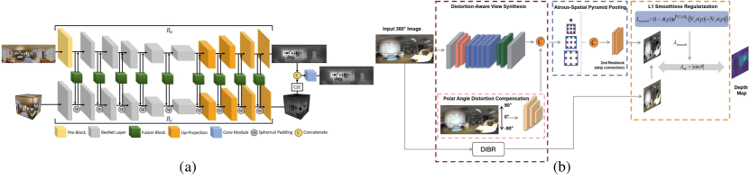
Supervised methods. “Supervised” means that the depth estimation methods directly have the corresponding ground-truth depth information to learn. In the supervised category, OmniDepth [338] generated synthetic panoramic datasets for supervised learning, via rending existing large-scale 3D datasets, which enables direct depth estimation on omnidirectional content in the form of equirectangular images. DistConv [339] put forward distortion-aware convolution filters, which endows a pinhole-trained model to smoothly work on equirectangular projection of panoramic data. In [340, 341], projection transformation is used to adapt existing rectilinear image datasets into equirectangular ones for learning panoramic depth estimation. They also leverage ring padding to enhance the continuity at the panorama border for a seamless estimation, which is similarly considered in panoramic semantic segmentation [306, 207] In [342], geometric structures are used as a prior to aid supervised panoramic depth estimation. Moreover, HoHoNet [343] and SliceNet [344] first squeezed the extracted feature maps into a horizontal 1D representation due to the assumption that indoor panoramas are aligned to the gravity vector, and then recovered the dense depth map predictions in the equirectangular projection. Unlike previous methods that calculated the shapes of convolution kernels according to the latitude coordinates [339] in a fixed manner, ACDNet [345] combined the convolution kernels with different dilation rates in an adaptive manner and improved the estimation in the equirectangular projection. There are also fusion-driven methods with the aim to exploit the advantages of both equirectangular- and cube-map projections [336, 346, 347], with methods including bidirectional fusion [336, 348], unidirectional fusion [346], and usage of an asymmetric architecture that leverages a transformer model in the cube-map branch and a convolutional neural network in the equirectangular branch [347]. OmniFusion [349] transforms a panorama into perspective image patches (i.e., tangent images) to attain patch-wise predictions and fuses the image features with 3D geometric features to enhance depth estimation quality. Such tangent image representations have also been used in [350] for estimating high-resolution depth maps. Regarding the advantages of the projection representations, equirectangular projection provides full-FoV observations and cube-map projection offers distortion-free representations [336] (see Fig. 13(a)). More recently, PanoFormer [351] put forward a panoramic transformer model to perform depth estimation, where the patch division is conducted in the spherical tangent domain to tackle distortions and geometric structures are modeled by using adding learnable token flows in the self-attention layers.
Unsupervised methods. “Unsupervised” means that the depth estimation methods do not require ground-truth depth information at the training time and thereby reduce the data preparation burden, which are beneficial for real applications. Unsupervised panoramic depth estimation is less visited compared to the supervised category, but it started to receive more attention. Zioulis et al. [352] formalized a full spherical disparity model and established a new untouched supervision scheme for spherical view synthesis using depth-image-based-rendering combined with spherical attention. Thereby, they facilitated a self-supervised monocular depth learning paradigm via spherical view synthesis. OlaNet [337] made an early self-supervised attempt to predict depth information in the equirectangular projection of images. They leveraged a combination of an anto-encoder based on convolutional neural networks, distortion-aware spherical view synthesis with depth-image-based rendering, and polar angle distortion compensation, to tackle the challenging self-supervised depth prediction task (Fig. 13(b)). Zhou et al. [353] extended PADENet [341] and combined unsupervised and supervised learning to improve panoramic depth estimation specifically in indoor scenes. In [354], gravity-aligned videos were used to facilitate self-supervised depth learning. They also combined supervised- and self-supervised learning to compensate the weaknesses of each learning method towards more accurate depth estimation. More recently, in [355], multi-modal masked pretraining was used to enhance panoramic depth completion, which aims to complete the depth channel of a single RGB-D pair captured from a panoramic 3D camera. Panoramic depth estimation and completion were also potentially useful for improving the perception ability and operational efficiency of mobile robots in large-scale environments [356].
V-C Visual Localization, Odometry, and SLAM
In this subsection, we review important applications of panoramic cameras related to the localization and mapping in robotic environments, including panoramic visual localization, panoramic visual odometry, and panoramic Simultaneous Localization And Mapping (SLAM), as shown in Fig. 14.
Panoramic visual localization. Visual localization is a task that recovers the camera location from database images based on the query images, which is important for many applications like intelligent vehicles and assisted pedestrian navigation [357]. To overcome the challenges in matching query and database images with various appearance variations like illumination variations, moving object variations, and orientation variations, panoramic cameras are usually applied. In [358], location recognition was revisited by conducting a panorama-to-panorama matching process and they found that it is preferable to aggregate individual pinhole views into a vector for matching, rather than extracting a single descriptor from an explicit panorama. In [359], omnidirectional observation was integrated to perform visual localization and found that the front- and back views are the most descriptive for long-term place recognition. Cheng et al. [357] proposed a Panoramic Annular Localizer (see Fig. 14(a)), which incorporates panoramic annular lens and active deep image descriptors in a visual localization system. CFVL [360, 361] designed a coarse-to-fine visual localization framework by using equirectangular representations in the coarse stage to keep feature consistency with the panorama-trained descriptor, and cube-map representations in the fine stage of key-point matching to conform to the planarity of the images. In [362], a localization framework is designed by using high-level semantic information such as detected landmarks and ground surface boundaries, which are obtained via an omnidirectional camera, and their localization is conducted via extended Kalman filter. In [363], semantic similarity was checked between query- and database images based on contrastive learning on a dataset of semantically-segmented images. Their database images are generated from panoramas which present wide-FoV that facilitates to correctly localize the query images where standard-FoV cameras may fail with non-overlapping FoVs. Moreover, rotation equivariant orientation estimation [364] and semantic graph embedding lifted in 3D space [365] are explored for panoramic place recognition based on omnidirectional images.
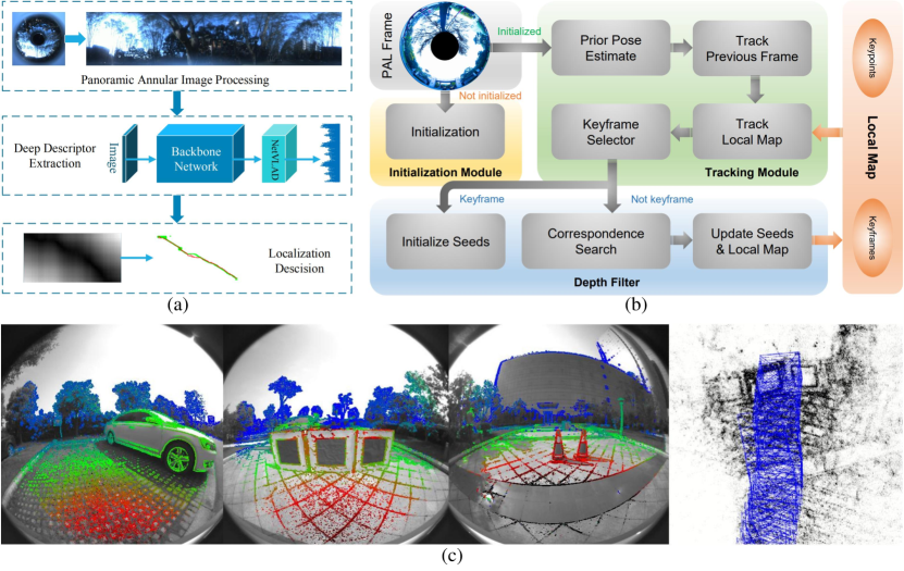
Panoramic visual odometry. Visual odometry estimates the egomotion of an agent by using only the continuous images captured by cameras attached to it [367]. One of the shared premise in visual odometry methods is that there must be enough overlaps between two adjacent frames for computing the relative motion. Pinhole-camera-based methods inevitably suffer in rapid-motion scenarios or dynamic scenarios with moving objects which may occupy most of the limited FoV. Incorporating panoramic observations is potential to help address the challenges in such scenarios. In [369], the benefits of using large-FoV cameras (e.g., fisheye or catadioptric) were investigated. They pointed out that wide-angle observations are advantageous in indoor scenes with more evenly-distributed features and the camera can help track features for long-term autonomy. However, in outdoor scenes, the loss of angular resolution for wider FoVs is intensified due to the higher depth range, and using large-FoV cameras is less accurate. PVO [370] took advantage of panoramic cameras by modifying the initialization process in the visual odometry and redefining the re-projection errors according to the panoramic camera model, which achieved higher precision in translation and rotation. Further, stereo omnidirectional cameras have been put use in [371, 372]. For example, dual fisheye cameras are used in [371] to obtain an ultra-wide FoV that ensures big image overlaps between frames and more spatially distributed points, where their joint optimization model helped to attain improved robustness over a pinhole camera model. Chen et al. [367] presented PALVO (Fig. 14(b)) by applying a Panoramic Annular Lens. Based on the panoramic annular camera model, they adapted initialization-, tracking-, and depth filter modules, which enabled PALVO to reach high robustness to rapid motion and dynamic objects. In [373], semantic information were used to further enhance PALVO, with semantic-guided keypoint extraction and correspondence search along epipolar curve, as well as semantic-based examination in pose optimization, which achieved more robust pose estimation. The Direct Sparse Odometry (DSO) [374] has also been augmented by attaining omnidirectional perception towards real-world applications [371, 375, 376]. For example, panoramic visual odometry has been applied with wearable devices to help people with visual impairments in indoor positioning and navigation [376].
Panoramic visual SLAM. Visual SLAM is a technology that estimates the poses of cameras and reconstructs the scenes, which usually extends the methods of visual odoemtry. In [377], a large-scale direct SLAM method is developed for panoramic- or wide-FoV fisheye cameras by directly formulating the tracking and mapping according to the omnidirectional camera model. By using two different omnidirectional imaging models, their system makes it possible to use a broad range of classical dioptric- or catadioptric imaging systems. They have verified their approach on data captured by a -FoV fisheye lens, and observed improved localization accuracy and enhanced robustness against fast camera rotations compared to the baseline approach using a standard camera. In [368], the ORB-SLAM2 framework [378] was extended by utilizing a unified spherical camera model and the semi-dense feature mapping. They validated their approach on real-world data collected by fisheye cameras set up on a car, of which the capturing FoV is around (see Fig. 14(c)). Panoramic annular camera has been applied in [379, 85]. PA-SLAM [379] extended PALVO [367] to a full panoramic visual SLAM system with loop closure and global optimization. They used a panoramic annular lens with a FoV of and a global shutter camera for experiments. They confirmed the better performance of PA-SLAM with respect to ORB-SLAM2 [378] and a cube-map-based fisheye SLAM method [380] on real-world data. PAL-SLAM [85] designed a feature-based SLAM for panoramic annular lens with a FoV of . They used a filtering mask to acquire features from the annular useful area, in order to conduct carefully-designed initialization, tracking, mapping, loop detecting, and global optimization. In this pipeline, they utilized the calibrated panoramic annular camera model to translate the mapped features onto a unit vector for the subsequent algorithms. The robust localization performance of PAL-SLAM are confirmed on large-scale outdoor and indoor panorama sequences, showing the advantages in comparison to a traditional SLAM method based on a camera with a narrow FoV. Additionally, there are some more mapping systems like landmark-tree mapping [381] and freespace mapping [382, 383] based on a single omnidirectional camera, 360ST-Mapping [384] based on online semantic-guided scene topological map reconstruction, as well as UPSLAM [385] based on a graph of panoramic images.
Furthermore, panoramic visual odometry and SLAM have also been implemented based on multiple sensors, e.g., using multi-cameras [386, 387, 388], with inertial sensors [389, 390, 391, 392], GPS [393], and LiDAR sensors [394]. Among them, LF-VIO [392, 395] put forward a universal framework that can work with diverse large-FoV cameras, where imaging points may even appear on the negative half plane. They verified the effectiveness of their visual-inertial-odometry framework on panoramic annular cameras with a FoV of and fisheye cameras with a FoV of , as well as sensor fusion systems with LiDAR measurements.
V-D Optical Flow Estimation, Object Detection, and Others
In addition to semantic segmentation and depth estimation, there are many potential information worth mining in panoramic images, such as optical flow estimation and object detection, as shown in Fig. 15. In this subsection, we review these panoramic vision tasks respectively.
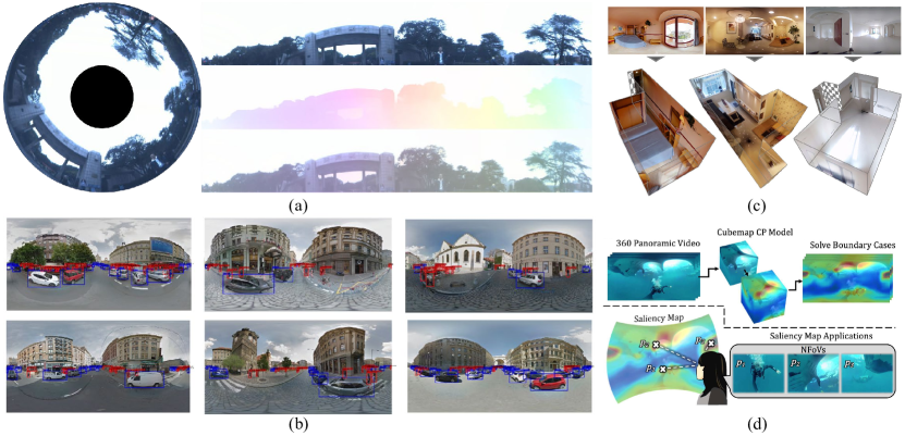
Optical flow estimation. Optical flow reflects pixel-by-pixel correspondence on time-series images and can be obtained by learning-based methods [400]. Flow estimation in panoramic content is an essential task, which enables autonomous vehicles and robots to acquire temporal cues of the surrounding scenes. Due to the lack of large-scale panoramic optical flow datasets, research on flow estimation mainly focuses on the domain adaptation. In order to leverage existing perspective models and benefit from advances in optical flow networks, two common perspectives are adapting models and datasets respectively. OmniFlowNet [401] adapted the famous LiteFlowNet [402] that designed for pinhole cameras to panoramic images and does not require retraining. Considering the equirectangular distortion imported by the spherical camera, they used the distortion-aware convolution to replace the regular grid-based 2D convolution via revising the coordinates of the convolution kernel. To address the distortion that introduced by spherical-to-plane projection in panoramic content, Bhandari et al. [403] proposed a spherical data augmentation to project perspective flow field onto the sphere and then reprojected to the equirectangular format. However, this data augmentation is offline and not flexible, and the perspective dataset should be transformed in advance for training. Yuan et al. [404] introduced a flow optical flow method by estimating on the tangent images. They directly use the off-the-shelf perspective optical flow method to estimate the flow field of panoramic images, and then apply the optical flow estimated under cubemap and icosahedron projection to benefit the panoramic flow estimation. OmniFlow [405] explored the human omnidirectional optical flow in a 3D indoor environment with a rendering engine, and generated a synthetic human optical flow dataset. Among these approaches, PanoFlow [396] (see Fig. 15(a)) presented a generic cyclic flow estimation framework, which can be adapted to any existing perspective learning-based model, e.g., RAFT [406] and CSFlow [407]. They generated the publicly available panoramic flow dataset Flow360 under city street scenes to facilitate training and quantitative analysis, and verified the precision and efficiency of their approach via a panoramic annular camera with a FoV of .
Object detection. Object detection in the surrounding environment is also a demanded task as the increasing interest in autonomous mobile systems such as drones and assistant robots. Early panoramic object detection systems[408, 409] used hand-designed operators, and the subsequent emergence of CNN has given new vitality to this field. Garanderie et al. [340] extended the Faster R-CNN [410] to support 3D object pose regression. Without changes to the network architecture, their extended model can be used on either rectilinear or equirectangular content by recovering 3D position using image transformation matrix and spherical coordinate projection. Yang et al. [411] leveraged VR videos on YouTube and proposed a bounding-FoV annotation to create a equirectangular panorama dataset for object detection. They then adapted YOLO [412] to panoramic contents with re-projections to realize panoramic object detection. Wang et al. [397] (Fig. 15(b)) proposed a distortion data augmentation method that uses the cropped car images to randomly back project in the equirectangular image plane. Considering that distortion of large objects is more pronounced, they aggregated the position information of anchor box into the network. Guerrero-Viu et al. [413] took advantage of the off-the-shelf layout estimation method [414] to simultaneously obtain the 2D object segmentation masks and the 3D bounding boxes. They also replaced all standard convolutions with EquiConvs [414] to implicitly adapt convolution kernels’ shape and size according to the distortions.
Other downstream tasks. In addition to the above applications, panoramic cameras are also integrated with deep learning algorithms in other fields. Layout Estimation: The 3D layout of a room specifies the positions, orientations, and the heights of the walls according to the vision point. Estimating the layout of a room by a single panorama can benefit robotics and VR/AR applications. LayoutNet [415] is a deep CNN that estimates the layout of an indoor scene from a single perspective or a panoramic image. They extended the annotations for the Stanford2D3D dataset [416] with room layout annotations. DuLa-Net [398] (Fig. 15(c)) fused the estimation under equirectangular images and perspective ceiling images via a two-stream network architecture. They also introduced Realtor360 dataset, which consist of Manhattan-world room layouts in panoramic format. CFL [414] proposed EquiConvs by deforming the shape of the kernels according to the geometrical priors of panoramas. It can predict complex geometries like non-Manhattan structures. More recently, DeepPanoContext[417] was introduced as the first learning-based pipeline that recovers 3D room layout and detailed shape, pose, and location for objects in the scene from a single panoramic image for holistic 3D scene understanding. Anomalous Detection: Anomalous detection is a task to detect anomalous objects that in a specific scene or behaving dangerously, which is important for intelligent panoramic video surveillance systems. Benito-Picazo et al. [418] developed a low energy consumption system on a raspberry for video anomalous object detection. The panorama videos are obtained via a Point Grey Ladybug 3 Spherical camera and then fed to the CNN to determine whether it contains any anomalous object. Saliency Prediction: Saliency prediction is a popular computer vision task which means predicting where humans look in an given image [419]. Consecutive saliency prediction in panoramic videos is vital for applications such as viewpoint guidance. Zhang et al. [420] explored the utility of the surrounding cue for saliency detection, and proposed BMS, which is a saliency model using simple image processing operations to leverage the topological structural cue in panoramas. Cheng et al. [399] (Fig. 15(d)) put forward a weakly-supervised spatial-temporal saliency prediction model to overcome large viewpoint variations in videos. They also collected a Wild-360 dataset where one-third frames are annotated with saliency heatmaps.
VI Conclusions and perspectives
The panoramic imaging optical system is given a high expectation of future intelligent perception sensor. It has shown great application potential in current scene understanding applications such as autonomous driving and robotics systems. Associated with the expectations are the challenges of design and fabrication, compressing a high-performance panoramic system into a compact space for multidimensional panoramic information acquisition. Although the parametric limitations of optical systems have constituted a huge obstacle on this path, innovative optical architectures, and emerging optical technologies have lit the light of this path. The rise of ultra-precision manufacturing provides strong support for micro-nano processing such as freeform surfaces, thin-plate optics, and metalens. These new optical engines provide an effective alternative to traditional optical components and support more design freedom to achieve new capabilities and high performance beyond traditional geometric optics. In the future, the panoramic imaging system will combine these emerging technologies towards compact, intelligent and multidimensional development to achieve more powerful panoramic scene environment perception and surrounding understanding.
This review article conducts a systematic and detailed literature analysis on the knowledge of panoramic optical systems and downstream perception applications, and clarifies the advantages, progress, limitations, future challenges, and directions for the improvement of panoramic optical systems. The article identifies the valuable challenges that panoramic perception needs to face from the aspects of optical system and algorithm application, including the following:
1) The new optical surface technology will contribute to the miniaturization, lightweight, and high performance of panoramic imaging systems.
2) Multi-FoV, multi-functional (e.g. zoom, polarization), high temporal resolution, and high spectral multidimensional perception of the panoramic optical systems will facilitate more new applications of scene understanding.
3) Based on the fusion of new intelligent sensors and computational imaging, the development of panoramic optical instruments for scene understanding will be promoted.
4) Combining a panoramic optical system with an ultra-wide FoV and an event sensor with an ultra dynamic range or an active sensing LiDAR with a same projection behavior for multi-modal robust surrounding perception.
5) Considering that the annotation on the entire panoramas is difficult and expensive to obtain, exploring algorithms with unsupervised or weakly supervised learning, or adapted from the existing pinhole domain to the panoramic domain will benefit practical applications.
In general, with the unique advantages of a large FoV, the panoramic optical systems will combine emerging sensors, ultra-precise optical manufacturing, computational imaging, and artificial intelligence to achieve ultra-high performance, new functions, small volume, and multidimensional sensing and low-power panoramic intelligent instruments to enhance the way humans observe the world and have a deeper and more realistic perception of the surroundings. The panoramic imaging system has transformed from traditional optics to intelligent computing optics, and will be applied in various applications such as autonomous driving, medical health, security monitoring, deep space exploration, deep sea exploration, celestial terrain detection, and intelligent robots, greatly improving our life and the way to perceive the environment.
References
- [1] D. Gledhill, G.-Y. Tian, D. Taylor, and D. Clarke, “Panoramic imaging - a review,” Comput. Graph., vol. 27, pp. 435–445, 2003.
- [2] A. Bonarini, P. Aliverti, and M. Lucioni, “An omnidirectional vision sensor for fast tracking for mobile robots,” IEEE Transactions on Instrumentation and Measurement, vol. 49, no. 3, pp. 509–512, 2000.
- [3] M. Jiang, R. Sogabe, K. Shimasaki, S. Hu, T. Senoo, and I. Ishii, “500-Fps omnidirectional visual tracking using three-axis active vision system,” IEEE Transactions on Instrumentation and Measurement, vol. 70, pp. 1–11, 2021.
- [4] Y. Liu, H. Yu, B. Huang, G. Yue, and B. Song, “Blind omnidirectional image quality assessment based on structure and natural features,” IEEE Transactions on Instrumentation and Measurement, vol. 70, pp. 1–11, 2021.
- [5] I. Kholodilin, Y. Li, and Q. Wang, “Omnidirectional vision system with laser illumination in a flexible configuration and its calibration by one single snapshot,” IEEE Transactions on Instrumentation and Measurement, vol. 69, no. 11, pp. 9105–9118, 2020.
- [6] L. Cao, G. Jiang, Z. Jiang, M. Yu, Y. Qi, and Y.-S. Ho, “Quality measurement for high dynamic range omnidirectional image systems,” IEEE Transactions on Instrumentation and Measurement, vol. 70, pp. 1–15, 2021.
- [7] X. Hu, Y. An, C. Shao, and H. Hu, “Distortion convolution module for semantic segmentation of panoramic images based on the image-forming principle,” IEEE Transactions on Instrumentation and Measurement, vol. 71, pp. 1–12, 2022.
- [8] R. Roriz, J. Cabral, and T. Gomes, “Automotive LiDAR technology: A survey,” IEEE Transactions on Intelligent Transportation Systems, 2021.
- [9] B. Gao, Y. Pan, C. Li, S. Geng, and H. Zhao, “Are we hungry for 3D LiDAR data for semantic segmentation? A survey of datasets and methods,” IEEE Transactions on Intelligent Transportation Systems, 2021.
- [10] D. Feng, C. Haase-Schütz, L. Rosenbaum, H. Hertlein, C. Glaeser, F. Timm, W. Wiesbeck, and K. Dietmayer, “Deep multi-modal object detection and semantic segmentation for autonomous driving: Datasets, methods, and challenges,” IEEE Transactions on Intelligent Transportation Systems, vol. 22, no. 3, pp. 1341–1360, 2021.
- [11] Y. Zhang, D. Sidibé, O. Morel, and F. Mériaudeau, “Deep multimodal fusion for semantic image segmentation: A survey,” Image and Vision Computing, vol. 105, p. 104042, 2021.
- [12] Y. Ming, X. Meng, C. Fan, and H. Yu, “Deep learning for monocular depth estimation: A review,” Neurocomputing, vol. 438, pp. 14–33, 2021.
- [13] J. P. Rolland, M. A. Davies, T. J. Suleski, C. Evans, A. Bauer, J. C. Lambropoulos, and K. Falaggis, “Freeform optics for imaging,” Optica, vol. 8, no. 2, pp. 161–176, 2021.
- [14] M. Y. Shalaginov, S. An, F. Yang, P. Su, D. Lyzwa, A. M. Agarwal, H. Zhang, J. Hu, and T. Gu, “Single-element diffraction-limited fisheye metalens.” Nano Letters, 2020.
- [15] J. Wang, X. Huang, J. Bai, K. Wang, and Y. Hua, “Design of high resolution panoramic annular lens system,” in Applied Optics and Photonics China, 2019.
- [16] S. Gao, L. Sun, Q. Jiang, H. Shi, J. Wang, K. Wang, and J. Bai, “Compact and lightweight panoramic annular lens for computer vision tasks,” Optics Express, vol. 30, no. 17, pp. 29 940–29 956, 2022.
- [17] J. M. Geary, Introduction to lens design: with practical ZEMAX examples. Willmann-Bell Richmond, VA, USA:, 2002.
- [18] F. Song, Introduction to Modern Optical System Design. Science Press, 2019.
- [19] J. Xiong, E. Hsiang, Z. He, T. Zhan, and S. Wu, “Augmented reality and virtual reality displays: emerging technologies and future perspectives,” Light, Science & Applications, vol. 10, 2021.
- [20] D. Cheng, Q. Wang, Y. Liu, H. Chen, D. Ni, X. Wang, C. Yao, Q. Hou, W. Hou, G. Luo, and Y. Wang, “Design and manufacture AR head-mounted displays: A review and outlook,” Light: Advanced Manufacturing, vol. 2, no. 3, pp. 350–369, 2021.
- [21] E. Hecht, “Optics 4th edition. optics,” Addison Wesley Longman Inc, vol. 1, p. 1998, 1998.
- [22] D. H. Sliney, “What is light? the visible spectrum and beyond,” Eye, vol. 30, pp. 222–229, 2016.
- [23] S. Arnold, “The electromagnetic spectrum,” The Patrick Moore Practical Astronomy Series, 2020.
- [24] W. Tobiska and A. Nusinov, “Iso 21348-process for determining solar irradiances,” in 36th COSPAR Scientific Assembly, vol. 36, 2006, p. 2621.
- [25] E. D. Cyan, “Handbook of chemistry and physics,” JAMA Internal Medicine, vol. 126, pp. 335–336, 1970.
- [26] L. Wang, C. Li, and C. Jin, “Design of catadioptric omnidirectional imaging system in solar blind UV,” Optics and Precision Engineering, vol. 19, pp. 1503–1509, 2011.
- [27] I. Powell, “Design study of an infrared panoramic optical system.” Applied Optics, vol. 35 31, pp. 6190–4, 1996.
- [28] J. E. Greivenkamp, Field guide to geometrical optics. SPIE press Bellingham, Washington, 2004, vol. 1.
- [29] M. Bass, Handbook of optics: volume ii-design, fabrication, and testing; sources and detectors; radiometry and photometry. McGraw-Hill Education, 2010.
- [30] G. C. Holst and R. G. Driggers, “Small detectors in infrared system design,” Optical Engineering, vol. 51, 2012.
- [31] E. M. Robinson, “Chapter 5 - focus, depth of field, and lenses,” in Crime Scene Photography (Third Edition), E. M. Robinson, Ed. San Diego: Academic Press, 2016, pp. 201–266.
- [32] D. S. Goodman, “General principles of geometric optics,” Hand Book of Optics, vol. 1, pp. 68–69, 1996.
- [33] F. Bettonvil, “Fisheye lenses,” WGN, Journal of the International Meteor Organization, vol. 33, pp. 9–14, 2005.
- [34] D. Schneider, E. Schwalbe, and H.-G. Maas, “Validation of geometric models for fisheye lenses,” ISPRS Journal of Photogrammetry and Remote Sensing, vol. 64, pp. 259–266, 2009.
- [35] J. S. Warren, “Modern optical engineering,” The Design of Optical Systems, 2008.
- [36] M. C. Dudzik, J. S. Accetta, and D. L. Shumaker, “The infrared & electro-optical systems handbook. electro-optical systems design, analysis, and testing, volume 4,,” Infrared information and analysis center ann arbor mi, Tech. Rep., 1993.
- [37] B. S. Carlson, “Comparison of modern ccd and cmos image sensor technologies and systems for low resolution imaging,” Proceedings of IEEE Sensors, vol. 1, pp. 171–176 vol.1, 2002.
- [38] R. K. Lenz and U. Lenz, “New developments in high-resolution image acquisition with ccd area sensors,” in Other Conferences, 1994.
- [39] V. Bockaert, “Sensor sizes,” Digital Photography Review., 2002.
- [40] B. Benjamin, “Practical optics: Testing different sensor sizes,” American Cinematographer: The International Journal of Film & Digital Production Techniques, vol. 97, pp. 90–99, 2016.
- [41] A. Uvarova, D. H. Nguyen, S. Gao, and A. Bakholdin, “Optical design of microscope objectives with low magnification,” in SPIE/COS Photonics Asia, 2021.
- [42] E. A. Tsyganok, A. Kozhina, and S. Gao, “Development of microscope lenses with uniform separation of optical illumination,” Optical Design and Testing XI, 2021.
- [43] Y. Luo, X. Huang, J. Bai, and R. Liang, “Compact polarization-based dual-view panoramic lens.” Applied Optics, vol. 56 22, pp. 6283–6287, 2017.
- [44] D.-H. Hwang, K. Aso, and H. Koike, “Toward human motion capturing with an ultra-wide fisheye camera on the chest,” 2019 IEEE Conference on Virtual Reality and 3D User Interfaces (VR), pp. 1524–1526, 2019.
- [45] D. Wagner, A. Mulloni, T. Langlotz, and D. Schmalstieg, “Real-time panoramic mapping and tracking on mobile phones,” 2010 IEEE Virtual Reality Conference (VR), pp. 211–218, 2010.
- [46] C.-H. Lin, L. Hsiao, J.-T. Hsaio, and H. Y. Lin, “Front view and panoramic side view videoscope lens system design.” Applied Optics, vol. 53 29, pp. H146–52, 2014.
- [47] H. Yuan, B. Wang, J. A. Zhang, and H. Li, “A novel method for geometric correction of multi-cameras in panoramic video system,” 2010 International Conference on Measuring Technology and Mechatronics Automation, vol. 1, pp. 248–251, 2010.
- [48] L. V. Cowan, J. Babington, G. Carles, M. A. Perciado, A. P. Wood, and A. R. Harvey, “360° snapshot imaging with a convex array of long-wave infrared cameras,” Imaging and Applied Optics 2019 (COSI, IS, MATH, pcAOP), 2019.
- [49] H. S. Lin, C.-C. Chang, H.-Y. Chang, Y.-Y. Chuang, T. Lin, and M. Ouhyoung, “A low-cost portable polycamera for stereoscopic 360° imaging,” IEEE Transactions on Circuits and Systems for Video Technology, vol. 29, pp. 915–929, 2019.
- [50] S. Thibault, J. R. Gauvin, M. Doucet, and M. Wang, “Enhanced optical design by distortion control,” in SPIE Optical Systems Design, 2005.
- [51] A. Ning, “Wide-angle lenses with reduced ghost reflections,” Oct. 28 2014, US Patent 8,873,167.
- [52] L. Fan and L. Lu, “Design of a simple fisheye lens,” Appl. Opt., vol. 58, no. 19, pp. 5311–5319, Jul 2019.
- [53] S. Thibault and J. C. Artonne, “Panomorph lenses: a low-cost solution for panoramic surveillance,” in SPIE Defense + Commercial Sensing, 2006.
- [54] S. Thibault, “Panomorph lenses: a new type of panoramic lens,” in International Optical Design Conference, 2006.
- [55] S. Thibault, J. Parent, H. Zhang, and P. Roulet, “Design, fabrication and test of miniature plastic panomorph lenses with 180° field of view,” in International Optical Design Conference, 2014.
- [56] W. Zhuang, “Research on key technology of single chip 360° panoramic imaging optical system,” Master’s thesis, Changchun University of Science and Technology, 2019.
- [57] H. Wu, X. Zeng, and P. Wang, “Design of catadioptric IR panoramic imaging optical system,” Infrared, 2019.
- [58] Y. Huang, Y. Fu, G. Zhang, and Z. Liu, “Modeling and analysis of a monocentric multi-scale optical system.” Optics Express, vol. 28 22, pp. 32 657–32 675, 2020.
- [59] E. J. Tremblay, D. L. Marks, D. J. Brady, and J. E. Ford, “Design and scaling of monocentric multiscale imagers.” Applied Optics, vol. 51 20, pp. 4691–702, 2012.
- [60] I. Stamenov, S. Olivas, A. Arianpour, I. P. Agurok, J. E. Ford, A. Johnson, and R. Stack, “Broad-spectrum fiber-coupled monocentric lens imaging,” in International Optical Design Conference, 2014, pp. IM3B–5.
- [61] Y. Wang, X. Meng, Z. Gu, and X. Mu, “The design of miniaturization and super wide angle monitor lens based on monocentric lens,” in 9th International Symposium on Advanced Optical Manufacturing and Testing Technologies: Meta-Surface-Wave and Planar Optics, vol. 10841, 2019, pp. 276–281.
- [62] C. Pernechele, Introduction to Panoramic Lenses, ser. SPIE Digital Library. SPIE, 2018.
- [63] ——, “Hyper-hemispheric and bifocal panoramic lenses,” in Electro-Optical and Infrared Systems: Technology and Applications X, vol. 8896, 2013, p. 889603.
- [64] ——, “Hyper hemispheric lens,” Optics Express, vol. 24, no. 5, pp. 5014–5019, 2016.
- [65] Q. Zhou, Y. Tian, J. Wang, and M. Xu, “Design and implementation of a high-performance panoramic annular lens,” Applied Optics, vol. 59, no. 36, pp. 11 246–11 252, 2020.
- [66] S. Gao, E. A. Tsyganok, and X. Xu, “Design of a compact dual-channel panoramic annular lens with a large aperture and high resolution,” Applied Optics, vol. 60, no. 11, pp. 3094–3102, 2021.
- [67] J. Wang, K. Yang, S. Gao, L. Sun, C. Zhu, K. Wang, and J. Bai, “High-performance panoramic annular lens design for real-time semantic segmentation on aerial imagery,” Optical Engineering, vol. 61, no. 3, p. 035101, 2022.
- [68] K. Zhang, X. Zhong, L. Zhang, and T. Zhang, “Design of a panoramic annular lens with ultrawide angle and small blind area,” Applied Optics, vol. 59, no. 19, pp. 5737–5744, 2020.
- [69] M. A. Brown, R. I. Hartley, and D. Nistér, “Minimal solutions for panoramic stitching,” 2007 IEEE Conference on Computer Vision and Pattern Recognition, pp. 1–8, 2007.
- [70] J. W. Kim, J. M. Ryu, and Y.-J. Kim, “Tolerance analysis and compensation method using zernike polynomial coefficients of omni-directional and fisheye varifocal lens,” Journal of The Optical Society of Korea, vol. 18, pp. 720–731, 2014.
- [71] C. Pernechele, L. Consolaro, G. H. Jones, G. M. Brydon, and V. D. Deppo, “Telecentric F-theta fisheye lens for space applications,” OSA Continuum, 2021.
- [72] S. Niu, J. Bai, X. Y. Hou, and G. Yang, “Design of a panoramic annular lens with a long focal length.” Applied Optics, vol. 46 32, pp. 7850–7, 2007.
- [73] Y. Yao, A. Geng, J. Bai, H. Wang, J. Guo, T. Xiong, Y. Luo, Z. Huang, and X. Y. Hou, “Design of a panoramic long-wave infrared athermal system,” Optical Engineering, vol. 55, 2016.
- [74] J. Wang, Y. Liang, and M. Xu, “Design of panoramic lens based on ogive and aspheric surface.” Optics Express, vol. 23 15, pp. 19 489–99, 2015.
- [75] Q. Xue and W. Chen, “Optical system design of space-based UV panoramic imager,” Infrared and Laser Engineering, vol. 43, no. 2, pp. 517–522, 2014.
- [76] T. Ma, J. Yu, P. Liang, and C. Wang, “Design of a freeform varifocal panoramic optical system with specified annular center of field of view,” Optics Express, vol. 19, no. 5, pp. 3843–3853, 2011.
- [77] J. Wang, A. Amani, C. Zhu, and J. Bai, “Design of a compact varifocal panoramic system based on the mechanical zoom method,” Applied Optics, vol. 60, no. 22, pp. 6448–6455, 2021.
- [78] Y.-h. Huang, Z.-y. Liu, Y.-g. Fu, and H. Zhang, “Design of a compact two-channel panoramic optical system,” Optics Express, vol. 25, no. 22, pp. 27 691–27 705, 2017.
- [79] J. Liu and Y. Wang, “Design of cemented compact two channel panoramic annular optical system,” in Applied Optics and Photonics China, 2019.
- [80] Y. Luo, J. Bai, X. Zhou, X. Huang, Q. Liu, and Y. Yao, “Non-blind area pal system design based on dichroic filter.” Optics Express, vol. 24 5, pp. 4913–4923, 2016.
- [81] N. Yu and F. Capasso, “Flat optics with designer metasurfaces,” Nature Materials, vol. 13, no. 2, pp. 139–150, 2014.
- [82] T. Yang, Y. Duan, D. Cheng, and Y. Wang, “Freeform imaging optical system design: Theories, development, and applications,” Acta Optica Sinica, 2021.
- [83] Y. Peng, Q. Sun, X. Dun, G. Wetzstein, W. Heidrich, and F. Heide, “Learned large field-of-view imaging with thin-plate optics,” ACM Transactions on Graphics (TOG), vol. 38, pp. 1 – 14, 2019.
- [84] M. Y. Shalaginov, S. An, F. Yang, P. Su, D. Lyzwa, A. Agarwal, H. Zhang, J. Hu, and T. Gu, “A single-layer panoramic metalens with 170° diffraction-limited field of view,” arXiv preprint arXiv:1908.03626, 2019.
- [85] D. Wang, J. Wang, Y. Tian, K. Hu, and M. Xu, “PAL-SLAM: a feature-based SLAM system for a panoramic annular lens,” Optics Express, vol. 30, no. 2, pp. 1099–1113, 2022.
- [86] L. E. Gurrieri and E. Dubois, “Acquisition of omnidirectional stereoscopic images and videos of dynamic scenes: a review,” Journal of Electronic Imaging, vol. 22, 2013.
- [87] S. Ji, Z. yang Qin, J. Shan, and M. Lu, “Panoramic slam from a multiple fisheye camera rig,” Isprs Journal of Photogrammetry and Remote Sensing, vol. 159, pp. 169–183, 2020.
- [88] D. Scaramuzza, “Omnidirectional camera,” Computer Vision, 2021.
- [89] K.-C. Huang, P.-Y. Chien, C.-A. Chien, H.-C. Chang, and J.-I. Guo, “A 360-degree panoramic video system design,” in Technical Papers of 2014 International Symposium on VLSI Design, Automation and Test, 2014, pp. 1–4.
- [90] H. Hua, N. Ahuja, and C. Gao, “Design analysis of a high-resolution panoramic camera using conventional imagers and a mirror pyramid,” IEEE Transactions on Pattern Analysis and Machine Intelligence, vol. 29, pp. 356–361, 2007.
- [91] O. Haggui, H. Bayd, B. Magnier, and A. Aberkane, “Human detection in moving fisheye camera using an improved YOLOv3 framework,” 2021 IEEE 23rd International Workshop on Multimedia Signal Processing (MMSP), pp. 1–6, 2021.
- [92] R. W. Wood, Physical optics. Macmillan, 1905.
- [93] W. Bond, “Lxxxix. a wide angle lens for cloud recording,” The London, Edinburgh, and Dublin Philosophical Magazine and Journal of Science, vol. 44, no. 263, pp. 999–1001, 1922.
- [94] R. Hill, “A lens for whole sky photographs,” Quarterly Journal of the Royal Meteorological Society, vol. 50, no. 211, pp. 227–235, 1924.
- [95] S. Thibault, “New generation of high-resolution panoramic lenses,” in SPIE Optical Engineering + Applications, 2007.
- [96] Y. Yan and J. M. Sasián, “Photographic zoom fisheye lens design for dslr cameras,” Optical Engineering, vol. 56, 2017.
- [97] S. Thibault, “Panoramic lens applications revisited,” in SPIE Photonics Europe, 2008.
- [98] R. Kingslake, “Development of the photographic objective,” in Photonics West - Lasers and Applications in Science and Engineering, 1985.
- [99] S. Thibault, “Panoramic lens an historical perspective: from sky lens to consumer wide angle freeform optics,” in International Optical Design Conference, 2021.
- [100] AEG, “Abänderung eines weitwinkelobjektivs (modification of a wide-angle lens,” Aug. 6 1935, DE patent 620538C.
- [101] K. Miyamoto, “Fish eye lens,” J. Opt. Soc. Am., vol. 54, no. 8, pp. 1060–1061, Aug 1964.
- [102] C. B. Martin, “Design issues of a hyperfield fisheye lens,” in Novel Optical Systems Design and Optimization VII, vol. 5524, 2004, pp. 84–92.
- [103] F. E. Sahin and A. R. Tanguay, “Distortion optimization for wide-angle computational cameras.” Optics Express, vol. 26 5, pp. 5478–5487, 2018.
- [104] G.-Y. Tian, D. Gledhill, D. Taylor, and D. Clarke, “Colour correction for panoramic imaging,” Proceedings Sixth International Conference on Information Visualisation, pp. 483–488, 2002.
- [105] A. Samy and Z. shan Gao, “Simplified compact fisheye lens challenges and design,” Journal of Optics, vol. 44, pp. 409–416, 2015.
- [106] L.-J. Lu, X.-Y. Hu, and C.-Y. Sheng, “Optimization method for ultra-wide-angle and panoramic optical systems,” Applied Optics, vol. 51, no. 17, pp. 3776–3786, 2012.
- [107] L. Fan and L. Lu, “Calculation of the wave aberration of field curvature and color aberrations of an ultrawide-angle optical system,” Optics Communications, vol. 479, p. 126414, 2021.
- [108] G. il Kweon and Y.-H. Choi, “Image-processing based panoramic camera employing single fisheye lens,” Journal of The Optical Society of Korea, vol. 14, pp. 245–259, 2010.
- [109] T. Ho and M. Budagavi, “Dual-fisheye lens stitching for 360-degree imaging,” in 2017 IEEE International Conference on Acoustics, Speech and Signal Processing (ICASSP), 2017, pp. 2172–2176.
- [110] W. Gao and S. Shen, “Dual-fisheye omnidirectional stereo,” in 2017 IEEE/RSJ International Conference on Intelligent Robots and Systems (IROS), 2017, pp. 6715–6722.
- [111] W. Song, X. Liu, Q. Cheng, Y. Huang, Y. Zheng, Y. Liu, and Y. Wang, “Design of a 360-deg panoramic capture system based on a smart phone,” Optical Engineering, vol. 59, pp. 015 101 – 015 101, 2020.
- [112] W. Ye, Z. H. Zeng, and F. Lin, “Design of compact panoramic lens,” in International Symposium on Advanced Optical Manufacturing and Testing Technologies (AOMATT), 2019.
- [113] W. Song, X. Liu, P. Lu, Y. Huang, D. Weng, Y. Zheng, Y. Liu, and Y. Wang, “Design and assessment of a 360° panoramic and high-performance capture system with two tiled catadioptric imaging channels.” Applied Optics, vol. 57 13, pp. 3429–3437, 2018.
- [114] D. Geng, H. tao Yang, C. Mei, and Y. Li, “Optical system design of space fisheye lens and performance analysis,” in Applied Optics and Photonics China, 2017.
- [115] O.-Y. Mang, S.-W. Huang, Y.-L. Chen, H.-H. Lee, and P.-K. Weng, “Design of wide-angle lenses for wireless capsule endoscopes,” Optical Engineering, vol. 46, p. 103002, 2007.
- [116] C.-T. Yen and J.-M. Zhang, “The vehicle zoom ultra wide angle lens design by using liquid lens technology,” Microsystem Technologies, vol. 28, pp. 195–208, 2019.
- [117] X. Peng and L. B. Kong, “Design of a real-time fiber-optic infrared imaging system with wide-angle and large depth of field,” Chinese Optics Letters, 2022.
- [118] S. Thibault, “Panomorph based panoramic vision sensors,” Vision Sensors and Edge Detection, p. 1, 2010.
- [119] ——, “Optical design of an hemispherical, long-wave infrared panomorph lens for total situational awareness,” in Defense + Commercial Sensing, 2009.
- [120] S. Thibault, J. Parent, H. Zhang, X. Du, and P. Roulet, “Consumer electronic optics: how small can a lens be: the case of panomorph lenses,” in Optics & Photonics - Optical Engineering + Applications, 2014.
- [121] S. Thibault, “Enhanced surveillance system based on panomorph panoramic lenses,” in SPIE Defense + Commercial Sensing, 2007.
- [122] ——, “Novel compact panomorph lens based vision system for monitoring around a vehicle,” in Photonics Europe, 2008.
- [123] J. Parent and S. Thibault, “Tolerancing panoramic lenses,” in Optical Engineering + Applications, 2009.
- [124] ——, “Spatial dependence of surface error slopes on tolerancing panoramic lenses,” Applied Optics, vol. 49, pp. 2686–2693, 2010.
- [125] S. Thibault, J. Parent, H. Zhang, M. Larivière-Bastien, A.-S. Poulin-Girard, A. Arfaoui, and P. Désaulniers, “Developments in modern panoramic lenses: lens design, controlled distortion, and characterization,” in International Conference on Optical Instruments and Technology, 2011.
- [126] A.-S. Poulin-Girard and S. Thibault, “Optical testing of panoramic lenses,” Optical Engineering, vol. 51, p. 053603, 2012.
- [127] H. Kim, J. Jung, and J. Paik, “Fisheye lens camera based surveillance system for wide field of view monitoring,” Optik, vol. 127, pp. 5636–5646, 2016.
- [128] Z. Zhuang and S. Thibault, “Numerical investigation of three-dimensional pupil model impact on the relative illumination in panomorph lenses,” Optical Engineering, vol. 56, 2017.
- [129] Z. Zhuang, S. Thibault, and J. Parent, “Analysis of three-dimensional entrance pupil model in panomorph lenses,” in International Optical Design Conference, 2017, pp. ITh2A–2.
- [130] B. Akdemir, A. N. Belbachir, and L. M. Svendsen, “Real-time vehicle localization and tracking using monocular panomorph panoramic vision,” in 2018 24th International Conference on Pattern Recognition (ICPR), 2018, pp. 2350–2355.
- [131] P. Roulet, P. Konen, M. Villegas, S. Thibault, and P. Garneau, “360° endoscopy using panomorph lens technology,” in BiOS, 2010.
- [132] S. Thibault, “IR panomorph lens imager and applications,” in SPIE Defense + Commercial Sensing, 2008.
- [133] J. S. Chahl and M. V. Srinivasan, “Reflective surfaces for panoramic imaging.” Applied Optics, vol. 36 31, pp. 8275–85, 1997.
- [134] R. B. Benosman and S. B. Kang, Panoramic vision : sensors, theory, and applications. Springer Science & Business Media, 2001.
- [135] G. il Kweon, K. T. Kim, G.-H. Kim, and H. sik Kim, “Folded catadioptric panoramic lens with an equidistance projection scheme.” Applied Optics, vol. 44 14, pp. 2759–67, 2005.
- [136] Y. Wang, Y. Lv, X. Xu, X. Gong, Z. Yu, and J. Geng, “Single-view calibration of a catadioptric camera based on a theodolite model,” Applied Optics, vol. 61, no. 9, pp. 2256–2266, 2022.
- [137] X. Gong, Y. Lv, X.-P. Xu, Z. Jiang, and Z. Sun, “High-precision calibration of omnidirectional camera using an iterative method,” IEEE Access, vol. 7, pp. 152 179–152 186, 2019.
- [138] F. Aziz, O. Labbani-Igbida, A. Radgui, and A. Tamtaoui, “Color-metric tensor for catadioptric systems,” 2016 IEEE International Conference on Image Processing (ICIP), pp. 1594–1598, 2016.
- [139] W. Wei and C. Zongsheng, “A cylindrical virtual space based catadioptric real-time panorama imaging system,” 2006 IEEE Conference on Robotics, Automation and Mechatronics, pp. 1–5, 2006.
- [140] F. Aziz, O. Labbani-Igbida, A. Radgui, and A. Tamtaoui, “A riemannian approach for free-space extraction and path planning using catadioptric omnidirectional vision,” Image and Vision Computing, vol. 95, p. 103872, 2020.
- [141] L. N. Arkhipova, A. A. Bagdasarov, O. V. Bagdasarova, and D. N. Shevchenko, “Circular-scan panoramic systems,” Journal of Optical Technology, vol. 83, p. 342, 2016.
- [142] G. il Kweon and M. Laikin, “Design of a mega-pixel grade catadioptric panoramic lens with the rectilinear projection scheme,” Journal of The Optical Society of Korea, vol. 10, pp. 67–75, 2006.
- [143] A. Torii and R. Klette, “Panoramic and 3D computer vision,” in ArtsIT, 2009.
- [144] W. Li and Y. F. Li, “Single-camera panoramic stereo imaging system with a fisheye lens and a convex mirror.” Optics Express, vol. 19 7, pp. 5855–67, 2011.
- [145] S.-M. Tseng, C.-W. Huang, Y.-T. Hsu, and J.-C. Yu, “Panoramic annular lens design of endoscope,” in 2017 IEEE International Conference on Consumer Electronics - Taiwan (ICCE-TW), 2017, pp. 101–102.
- [146] S.-M. Tseng, J.-C. Yu, Y.-T. Hsu, C.-W. Huang, Y. F. Tsai, and W. Cheng, “Panoramic endoscope based on convex parabolic mirrors,” Optical Engineering, vol. 57, 2018.
- [147] M. Ou-Yang and W. de Jeng, “Design and analysis of radial imaging capsule endoscope (rice) system.” Optics Express, vol. 19 5, pp. 4369–83, 2011.
- [148] R. Katkam, B. Banerjee, C. Y. Huang, X. Zhu, L. H. Ocampo, J.-L. Kincade, and R. Liang, “Compact dual-view endoscope without field obscuration,” Journal of Biomedical Optics, vol. 20, 2015.
- [149] M.-J. Sheu, C.-W. Chiang, W.-S. Sun, J.-J. Wang, and J.-W. Pan, “Dual view capsule endoscopic lens design,” Optics Express, vol. 23 7, pp. 8565–75, 2015.
- [150] G. Lopes, A. F. Ribeiro, and N. Pereira, “Catadioptric system optimisation for omnidirectional robocup msl robots,” in RoboCup, 2011.
- [151] G. Krishnan and S. K. Nayar, “Cata-fisheye camera for panoramic imaging,” in 2008 IEEE Workshop on Applications of Computer Vision, 2008, pp. 1–8.
- [152] H. M. Spencer, J. M. Rodgers, and J. M. Hoffman, “Optical design of a panoramic, wide spectral band, infrared fisheye lens,” in International Optical Design Conference, 2006.
- [153] I. L. Kecskes, E. M. Engel, C. Wolfe, and G. Thomson, “Low-cost panoramic infrared surveillance system,” in Defense + Security, 2017.
- [154] J. M. Nichols, J. R. Waterman, R. T. Menon, and J. W. Devitt, “Performance characteristics of a submarine panoramic infrared imaging sensor,” in Defense + Commercial Sensing, 2010.
- [155] X. Zeng, J. Lan, and X. Gao, “The design of a catadioptric omnidirectional thermal imaging system based on the combination of genetic algorithm and gradient descent,” Optics and Laser Technology, vol. 122, p. 105861, 2020.
- [156] S. Aburmad, “Panoramic thermal imaging: challenges and tradeoffs,” in Defense + Security Symposium, 2014.
- [157] R. Qiu, W. Dou, J. Kan, K. Yu, H. Wu, and J. Yang, “Optical design of wide-angle catadioptric lens for LWIR earth sensors,” in Applied Optics and Photonics China, 2017.
- [158] T.-Y. Lim and S.-C. Park, “Design of a catadioptric system with corrected color aberration and flat petzval curvature using a graphically symmetric method,” Current Optics and Photonics, vol. 2, no. 4, pp. 324–331, 2018.
- [159] C. Gimkiewicz, C. Urban, E. Innerhofer, P. Ferrat, S. Neukom, G. Vanstraelen, and P. Seitz, “Ultra-miniature catadioptrical system for an omnidirectional camera,” in SPIE Photonics Europe, 2008.
- [160] W. Stürzl, D. Soccol, J. Zeil, N. Boeddeker, and M. V. Srinivasan, “Rugged, obstruction-free, mirror-lens combination for panoramic imaging.” Applied Optics, vol. 47 32, pp. 6070–8, 2008.
- [161] P.-H. Huang, M.-F. Chen, Y.-H. Chen, T.-M. Huang, and C.-Y. Chan, “Geometric calibration of omnidirectional images for panoramic total internal reflection lens,” Frontiers in Optics, 2010.
- [162] M. Aikio and J.-T. Mäkinen, “Omnidirectional lens captures 360 degree panoramic view,” in Applied Industrial Optics: Spectroscopy, Imaging and Metrology, 2015, pp. AITh2F–1.
- [163] M. Aikio, “Omnidirectional lenses for low cost laser scanners,” in Advanced Microsystems for Automotive Applications 2011, 2011, pp. 167–174.
- [164] W. Stürzl, N. Boeddeker, L. Dittmar, and M. Egelhaaf, “Mimicking honeybee eyes with a 280 degrees field of view catadioptric imaging system.” Bioinspiration & Biomimetics, vol. 5 3, p. 036002, 2010.
- [165] R. C. C. Wang, M. J. Deen, D. Armstrong, and Q. Fang, “Development of a catadioptric endoscope objective with forward and side views.” Journal of Biomedical Optics, vol. 16 6, p. 066015, 2011.
- [166] J. Ma, M. Simkulet, and J. Smith, “C-view omnidirectional endoscope for minimally invasive surgery/diagnostics,” in Medical Imaging 2007: Visualization and Image-Guided Procedures, vol. 6509, 2007, p. 65090C.
- [167] D. Cheng, C. Gong, C. Xu, and Y. Wang, “Design of an ultrawide angle catadioptric lens with an annularly stitched aspherical surface.” Optics Express, vol. 24 3, pp. 2664–77, 2016.
- [168] F. Zhou, X. Chen, and H. Tan, “Double distortion correction method in a catadioptric vision system with a conic mirror.” Journal of the Optical Society of America. A, Optics, Image Science, and Vision, vol. 34 9, pp. 1651–1658, 2017.
- [169] Z. Ye, H.-B. Wang, J. Xiong, and K. Wang, “Ghost panorama using a convex mirror,” Optics Letters, vol. 46, no. 21, pp. 5389–5392, 2021.
- [170] Z. Yang, B. Hu, X. Zhang, F. Liu, and L. Yan, “Design of low-light-level panoramic imaging system,” Journal of Applied Optics, vol. 36, pp. 24–28, 2015.
- [171] O. Furxhi, J. Frascati, and R. G. Driggers, “Design, demonstration and testing of low F-number LWIR panoramic imaging relay optics,” in Defense + Security, 2018.
- [172] H. Zhang, E. A. Tsyganok, X.-P. Xu, N. Zhang, and J. Lv, “A novel car panoramic system based on catadioptric structure with dual-band operating mode,” in SPIE/COS Photonics Asia, 2020.
- [173] L. Wang, “Optical design for dual spectral panoramic imaging system applied in corona detector,” Acta Photonica Sinica, vol. 39, pp. 1770–1774, 2010.
- [174] D.-M. Córdova-Esparza, J. R. Terven, J.-A. Romero-González, and A. Ramirez-Pedraza, “Three-dimensional reconstruction of indoor and outdoor environments using a stereo catadioptric system,” Applied Sciences, vol. 10, p. 8851, 2020.
- [175] Y. J. Ju, K. Lee, and J. H. Jo, “Optical design of a reflective omnidirectional optical system to be used simultaneously in visible and lwir wavelength range,” in Optical Systems Design, 2018.
- [176] Y. J. Ju, J. H. Jo, and J. M. Ryu, “Optical design of reflecting omnidirectional zoom optical system with peripheral half-field of view from 110° to 72° for day and night surveillance,” Optik, 2020.
- [177] L. C. Kogos, Y. Li, J. Liu, Y. Li, L. Tian, and R. Paiella, “Plasmonic ommatidia for lensless compound-eye vision,” Nature Communications, vol. 11, 2020.
- [178] S. Viollet, S. Godiot, R. Leitel, W. Buss, P. Breugnon, M. Menouni, R. Juston, F. Expert, F. Colonnier, G. L’Eplattenier, A. Brückner, F. Kraze, H. A. Mallot, N. H. Franceschini, R. Pericet-Camara, F. Ruffier, and D. Floreano, “Hardware architecture and cutting-edge assembly process of a tiny curved compound eye,” Sensors, vol. 14, pp. 21 702 – 21 721, 2014.
- [179] S. J. Olivas, A. Arianpour, I. Stamenov, R. Morrison, R. A. Stack, A. R. Johnson, I. P. Agurok, and J. E. Ford, “Image processing for cameras with fiber bundle image relay,” Applied Optics, vol. 54, no. 5, pp. 1124–1137, 2015.
- [180] H. Kinoshita, K. Hoshino, K. Matsumoto, and I. Shimoyama, “Thin compound eye camera with a zooming function by reflective optics,” 18th IEEE International Conference on Micro Electro Mechanical Systems, 2005. MEMS 2005., pp. 235–238, 2005.
- [181] R. Ueno, K. Suzuki, M. Kobayashi, H. Kwon, H. Honda, and H. Funaki, “Compound-eye camera module as small as 8.5 8.5 6.0 mm for 26 k-resolution depth map and 2-mpix 2d imaging,” IEEE Photonics Journal, vol. 5, pp. 6 801 212–6 801 212, 2013.
- [182] S. Wu, T. Jiang, G. Zhang, B. Schoenemann, F. Neri, M. Zhu, C. Bu, J. Han, and K.-D. Kuhnert, “Artificial compound eye: a survey of the state-of-the-art,” Artificial Intelligence Review, vol. 48, pp. 573–603, 2017.
- [183] Y. Cheng, J. Cao, Y. Zhang, and Q. Hao, “Review of state-of-the-art artificial compound eye imaging systems,” Bioinspiration & Biomimetics, vol. 14, no. 3, p. 031002, 2019.
- [184] W.-L. Liang, J.-G. Pan, and G.-D. J. Su, “One-lens camera using a biologically based artificial compound eye with multiple focal lengths,” Optica, 2019.
- [185] Y. Sato, T. Ebihara, K. Mizutani, and N. Wakatsuki, “Design of a wide-angle compound eye acoustic lens system suitable for multi-user underwater acoustic communication,” Japanese Journal of Applied Physics, vol. 60, 2021.
- [186] S. Zhang, Q. Wu, C. Liu, T. Wang, H. Zhang, J. Wang, Y. Ding, J. Chi, W. Xu, Y. Xiang et al., “Bio-inspired spherical compound eye camera for simultaneous wide-band and large field of view imaging,” Optics Express, vol. 30, no. 12, pp. 20 952–20 962, 2022.
- [187] H. L. Phan, J. Yi, J. Bae, H. Ko, S. Lee, D. Cho, J.-M. Seo, and K. in Koo, “Artificial compound eye systems and their application: A review,” Micromachines, vol. 12, 2021.
- [188] H. S. Son, D. L. Marks, E. Tremblay, J. E. Ford, J. Hahn, R. A. Stack, A. Johnson, P. McLaughlin, J. M. Shaw, J. Kim et al., “A multiscale, wide field, gigapixel camera,” in Computational Optical Sensing and Imaging, 2011, p. JTuE2.
- [189] D. J. Brady, M. E. Gehm, R. A. Stack, D. L. Marks, D. S. Kittle, D. R. Golish, E. Vera, and S. D. Feller, “Multiscale gigapixel photography,” Nature, vol. 486, pp. 386–389, 2012.
- [190] I. N. Stamenov, I. P. Agurok, and J. E. Ford, “Optimization of two-glass monocentric lenses for compact panoramic imagers: general aberration analysis and specific designs.” Applied Optics, vol. 51 31, pp. 7648–61, 2012.
- [191] J. E. Ford, “System optimization of compact monocentric lens imagers,” Frontiers in Optics, 2013.
- [192] J. E. Ford, I. N. Stamenov, S. Karbasi, A. Arianpour, N. Motamedi, I. P. Agurok, R. A. Stack, A. R. Johnson, R. L. Morrison, J. Mott, E. K. Martin, C. LaReau, B. Giffel, J. Pessin, R. Tennill, and P. Onorato, “Panoramic imaging via curved fiber bundles,” Rundbrief Der Gi-fachgruppe 5.10 Informationssystem-architekturen, 2015.
- [193] I. N. Stamenov, I. P. Agurok, and J. E. Ford, “Optimization of high-performance monocentric lenses.” Applied Optics, vol. 52 34, pp. 8287–304, 2013.
- [194] R. Kingslake, A history of the photographic lens. Academic Press, 1989.
- [195] I. N. Stamenov, I. P. Agurok, and J. E. Ford, “Capabilities of monocentric objective lenses,” Rundbrief Der Gi-fachgruppe 5.10 Informationssystem-architekturen, 2013.
- [196] I. Stamenov, Panoramic monocentric lens imaging. University of California, San Diego, 2014.
- [197] I. N. Stamenov, A. Arianpour, S. J. Olivas, I. P. Agurok, A. R. Johnson, R. A. Stack, R. L. Morrison, and J. E. Ford, “Panoramic monocentric imaging using fiber-coupled focal planes.” Optics Express, vol. 22 26, pp. 31 708–21, 2014.
- [198] W. Pang and D. J. Brady, “Galilean monocentric multiscale optical systems.” Optics Express, vol. 25 17, pp. 20 332–20 339, 2017.
- [199] G. Schuster, W. M. Mellette, and J. E. Ford, “Folded monocentric imager with deformable mirror focus.” Applied Optics, vol. 56 12, pp. 3435–3444, 2017.
- [200] F. Liu, Y. Wei, P. li Han, J.-W. Liu, and X. Shao, “Design of monocentric wide field-of-view and high-resolution computational imaging system,” Acta Physica Sinica, 2019.
- [201] G. M. Schuster, D. G. Dansereau, G. Wetzstein, and J. E. Ford, “Panoramic single-aperture multi-sensor light field camera,” Optics Express, vol. 27, no. 26, pp. 37 257–37 273, 2019.
- [202] X. Jin, K. Li, C. Li, and X. Sun, “Point spread function for the wide-field-of-view plenoptic cameras.” Optics Express, vol. 29 15, pp. 23 764–23 776, 2021.
- [203] E. Simioni, C. Pernechele, C. Re, L. Lessio, and G. Cremonese, “Geometrical calibration for the panrover: A stereo omnidirectional system for planetary rover,” ISPRS - International Archives of the Photogrammetry, Remote Sensing and Spatial Information Sciences, pp. 1151–1158, 2020.
- [204] C. Gong, D. Cheng, C. Xu, and Y. Wang, “Design of a novel panoramic lens without central blindness,” in International Conference on Optical Instruments and Technology, 2015.
- [205] R. Opromolla, G. Fasano, G. Rufino, M. Grassi, C. Pernechele, and C. Dionisio, “A new star tracker concept for satellite attitude determination based on a multi-purpose panoramic camera,” Acta Astronautica, vol. 140, pp. 166–175, 2017.
- [206] B. A. Palmer, G. Taylor, V. Brumfeld, D. Gur, M. Shemesh, N. Elad, A. Osherov, D. Oron, S. Weiner, and L. Addadi, “The image-forming mirror in the eye of the scallop,” Science, vol. 358, pp. 1172 – 1175, 2017.
- [207] K. Yang, X. Hu, L. M. Bergasa, E. Romera, and K. Wang, “PASS: Panoramic annular semantic segmentation,” IEEE Transactions on Intelligent Transportation Systems, vol. 21, no. 10, pp. 4171–4185, 2020.
- [208] P. Greguss, “Panoramic security,” in Holographic Optical Security Systems, vol. 1509, 1991, pp. 55–66.
- [209] ——, “Panoramic imaging block for three-dimensional space,” Jan. 28 1986, US Patent 4,566,763.
- [210] I. Powell, “Panoramic lens,” Applied Optics, vol. 33, no. 31, pp. 7356–7361, 1994.
- [211] V. A. Solomatin, “A panoramic video camera,” Journal of Optical Technology, vol. 74, pp. 815–817, 2007.
- [212] Z. Huang, J. Bai, and X. Y. Hou, “Design of panoramic stereo imaging with single optical system.” Optics Express, vol. 20 6, pp. 6085–96, 2012.
- [213] Z. Huang, J. Bai, T. Lu, and X. Y. Hou, “Stray light analysis and suppression of panoramic annular lens.” Optics Express, vol. 21 9, pp. 10 810–20, 2013.
- [214] W. Zhu, M. S. Zhang, X. Kang, L. Ren, and L. Tian, “Catadioptric lens optical simulation and unwrapped distortion correction algorithm,” in Other Conferences, 2012.
- [215] D. R. Matthys, J. A. Gilbert, and P. Greguss, “Endoscopic measurement using radial metrology with digital correlation,” Optical Engineering, vol. 30, pp. 1455–1460, 1991.
- [216] D. R. Matthys, J. A. Gilbert, and J. T. Puliparambil, “Endoscopic inspection using a panoramic annular lens,” in SPIE Optics + Photonics, 1991.
- [217] J. T. Puliparambil, “Panoramic imaging and holographic interferometry using a panoramic annular lens,” Ph.D. dissertation, Marquette University, 1992.
- [218] D. Hui, M. Zhang, Z. Geng, Y. Zhang, J. Duan, A. Shi, L. Hui, Q. Fang, and Y. Liu, “Designs for high performance PAL-based imaging systems.” Applied Optics, vol. 51 21, pp. 5310–7, 2012.
- [219] Q. Liu, J. Bai, and Y. Luo, “Design of high resolution panoramic endoscope imaging system based on freeform surface,” in Journal of Physics: Conference Series, vol. 680, no. 1, 2016, p. 012011.
- [220] C. Su, X. Zhou, H. Li, Q. Yang, Z. Wang, and X. Liu, “360 deg full-parallax light-field display using panoramic camera.” Applied Optics, vol. 55 17, pp. 4729–35, 2016.
- [221] X. Zhou and J. Bai, “Distortion control for panoramic annular lens with Q-type aspheres,” in Photonics Asia, 2014.
- [222] X. Zhou, J. Bai, C. Wang, X. Hou, and K. Wang, “Comparison of two panoramic front unit arrangements in design of a super wide angle panoramic annular lens,” Applied Optics, vol. 55, no. 12, pp. 3219–3225, 2016.
- [223] H. Yu, J. Zhou, and J. Li, “Research on fov extension for eva astronaut based on panoramic annular optical system,” Manned Spaceflight, 2018.
- [224] X. Huang and J. Bai, “Analysis of the imaging performance of panoramic annular lens with conic conformal dome,” in Applied Optics and Photonics China, 2015.
- [225] X. Wang and Q. Xue, “Optical system design of an atmospheric detector with nadir view and omnidirectional limb view.” Applied Optics, vol. 56 26, pp. 7454–7461, 2017.
- [226] X. Wang, X. Zhong, R. Zhu, and F. Gao, “Nadir and omnidirectional limb imaging spectrometer based on acousto-optic tunable filter,” Optics Communications, 2019.
- [227] X. Li, D. Feng, and Y. Xiang, “Refractive-diffractive hybrid panoramic annular optical system design,” Laser & Optoelectronics Progress, 2019.
- [228] X. Wang, X. Zhong, R. Zhu, F. Gao, and Z. Li, “Extremely wide-angle lens with transmissive and catadioptric integration,” Applied Optics, vol. 58, no. 16, pp. 4381–4389, 2019.
- [229] A. Amani, J. Bai, and X. Huang, “Dual-view catadioptric panoramic system based on even aspheric elements,” Applied Optics, vol. 59, no. 25, pp. 7630–7637, 2020.
- [230] V. Gruev and T. York, “High resolution ccd polarization imaging sensor,” in Proceedings of the International Image Sensor Workshop, Sapporo, Japan, 2011, pp. 8–11.
- [231] Y. Horita, K. Shibata, K. Maeda, and Y. Hayashi, “Omni-directional polarization image sensor based on an omni-directional camera and a polarization filter,” in 2009 Sixth IEEE International Conference on Advanced Video and Signal Based Surveillance, 2009, pp. 280–285.
- [232] S. Araki, K. Maeda, K. Shibata, and Y. Horita, “High quality panoramic image generation using multiple panoramic annular lens images,” in 2010 IEEE International Conference on Image Processing, 2010, pp. 1213–1216.
- [233] S. Araki, K. Shibata, and Y. Horita, “Subjective verification of high quality panoramic image generated by multiple PAL images,” in 2012 IEEE International Conference on Consumer Electronics (ICCE), 2012, pp. 126–127.
- [234] K. Shibata, S. Araki, K. Maeda, and Y. Horita, “High‐quality panoramic image generation using multiple pal images,” Electronics and Communications in Japan, vol. 97, pp. 58–66, 2014.
- [235] K. Katayama, K. Shibata, and Y. Horita, “Detection and tracking an object in omni-directional images using particle filter,” 2012 Proceedings of SICE Annual Conference (SICE), pp. 1040–1043, 2012.
- [236] D. Sun, X. Huang, and K. Yang, “A multimodal vision sensor for autonomous driving,” in Counterterrorism, Crime Fighting, Forensics, and Surveillance Technologies III, vol. 11166, 2019, p. 111660L.
- [237] C. Xu, D. Cheng, and Y. Wang, “Optical design of a dual-channel two-focal-length system by utilizing azimuth property of pal structure,” in SPIE/COS Photonics Asia, 2016.
- [238] Y. Luo, J. Bai, and Y. Yao, “Design of vari-focal panoramic annular lenses based on alvarez surfaces,” in Photonics Asia, 2014.
- [239] X. Bian, T. Ma, and J. Zhang, “A design of panoramic lens system to realize the projection from the local annular object field to rectangular image field by using freeform surfaces,” in SPIE/COS Photonics Asia, 2016.
- [240] L. Chen, Q. Yuan, J. Ye, N. Xu, X. Cao, and Z. Gao, “Design of a compact dual-view endoscope based on a hybrid lens with annularly stitched aspheres,” Optics Communications, vol. 453, p. 124346, 2019.
- [241] L. Chen, Q. Yuan, N. Xu, X. Cao, and Z. Gao, “Compact dual-view endoscope imaging system based on annularly stitched aspheres,” in Optics, Photonics and Digital Technologies for Imaging Applications VI, vol. 11353, 2020, p. 113531M.
- [242] D. Gledhill, G. Y. Tian, D. Taylor, and D. Clarke, “3D reconstruction of a region of interest using structured light and stereo panoramic images,” in Proceedings. Eighth International Conference on Information Visualisation, 2004. IV 2004., 2004, pp. 1007–1012.
- [243] J. Wang, J. Bai, K. Wang, and S. Gao, “Design of stereo imaging system with a panoramic annular lens and a convex mirror,” Optics Express, vol. 30, no. 11, pp. 19 017–19 029, 2022.
- [244] L. Li and A. Y. Yi, “Design and fabrication of a freeform microlens array for a compact large-field-of-view compound-eye camera.” Applied Optics, vol. 51 12, pp. 1843–52, 2012.
- [245] J. Ye, L. Chen, X. Li, Q. Yuan, and Z. Gao, “Review of optical freeform surface representation technique and its application,” Optical Engineering, vol. 56, 2017.
- [246] F. Duerr and H. Thienpont, “Freeform imaging systems: Fermat’s principle unlocks “first time right” design,” Light, Science & Applications, vol. 10, 2021.
- [247] K. P. Thompson and J. P. Rolland, “Freeform optical surfaces: A revolution in imaging optical design,” Optics & Photonics News, vol. 23, pp. 30–35, 2012.
- [248] S. Wills, “Freeform optics: Notes from the revolution,” Optics & Photonics News, vol. 28, pp. 34–41, 2017.
- [249] J. Reimers, A. Bauer, K. P. Thompson, and J. P. Rolland, “Freeform spectrometer enabling increased compactness,” Light, Science & Applications, vol. 6, 2017.
- [250] A. Bauer, E. M. Schiesser, and J. P. Rolland, “Starting geometry creation and design method for freeform optics,” Nature Communications, vol. 9, no. 1, pp. 1–11, 2018.
- [251] F. Heide, Q. Fu, Y. Peng, and W. Heidrich, “Encoded diffractive optics for full-spectrum computational imaging,” Scientific Reports, vol. 6, no. 1, pp. 1–10, 2016.
- [252] G. W. Forbes, “Shape specification for axially symmetric optical surfaces.” Optics Express, vol. 15 8, pp. 5218–26, 2007.
- [253] ——, “Robust and fast computation for the polynomials of optics.” Optics Express, vol. 18 13, pp. 13 851–62, 2010.
- [254] ——, “Robust, efficient computational methods for axially symmetric optical aspheres.” Optics Express, vol. 18 19, pp. 19 700–12, 2010.
- [255] D. Cheng, X.-J. Chen, C. Xu, Y. Hu, and Y. tian Wang, “Optical description and design method with annularly stitched aspheric surface.” Applied Optics, vol. 54 34, pp. 10 154–62, 2015.
- [256] X. Shao, F. Liu, W. Li, L. Yang, S. Yang, and J. Liu, “Latest progress in computational imaging technology and application,” Laser Optoelectronics Progress, vol. 57, no. 2, p. 020001, 2020.
- [257] Y. Peng, Q. Fu, H. Amata, S. Su, F. Heide, and W. Heidrich, “Computational imaging using lightweight diffractive-refractive optics.” Optics Express, vol. 23 24, pp. 31 393–407, 2015.
- [258] Q. Jiang, H. Shi, L. Sun, S. Gao, K. Yang, and K. Wang, “Annular computational imaging: Capture clear panoramic images through simple lens,” arXiv preprint arXiv:2206.06070, 2022.
- [259] V. Sitzmann, S. Diamond, Y. Peng, X. Dun, S. P. Boyd, W. Heidrich, F. Heide, and G. Wetzstein, “End-to-end optimization of optics and image processing for achromatic extended depth of field and super-resolution imaging,” ACM Transactions on Graphics (TOG), vol. 37, pp. 1 – 13, 2018.
- [260] Q. Sun, J. Zhang, X. Dun, B. Ghanem, Y. Peng, and W. Heidrich, “End-to-end learned, optically coded super-resolution spad camera,” ACM Transactions on Graphics (TOG), vol. 39, pp. 1 – 14, 2020.
- [261] Y. Peng, Q. Fu, F. Heide, and W. Heidrich, “The diffractive achromat full spectrum computational imaging with diffractive optics,” SIGGRAPH ASIA 2016 Virtual Reality meets Physical Reality: Modelling and Simulating Virtual Humans and Environments, 2016.
- [262] B. Qi, W. Chen, X. Dun, X. Hao, R. Wang, X. Liu, H. Li, and Y. Peng, “All-day thin-lens computational imaging with scene-specific learning recovery.” Applied Optics, vol. 61 4, pp. 1097–1105, 2022.
- [263] Y. Zhang, L. G. Zimin, J. Ji, S. Ikezawa, and T. Ueda, “Real scene capturing using spherical single-element lens camera and improved restoration algorithm for radially variant blur.” Optics Express, vol. 20 25, pp. 27 569–88, 2012.
- [264] Q. Sun, C. Wang, Q. Fu, X. Dun, and W. Heidrich, “End-to-end complex lens design with differentiate ray tracing,” ACM Transactions on Graphics (TOG), vol. 40, pp. 1 – 13, 2021.
- [265] W. T. Xie, Y. Dai, R. Wang, and K. Sumathy, “Concentrated solar energy applications using fresnel lenses: A review,” Renewable & Sustainable Energy Reviews, vol. 15, pp. 2588–2606, 2011.
- [266] X. Dun, H. Ikoma, G. Wetzstein, Z. Wang, X. Cheng, and Y. Peng, “Learned rotationally symmetric diffractive achromat for full-spectrum computational imaging,” Optica, vol. 7, no. 8, pp. 913–922, 2020.
- [267] J. Huo, Y. Hu, and B. Cheng, “History and application of diffractive optics technology,” Laser & Optoelectronics Progress, 2022.
- [268] B. Li, W. Piyawattanametha, and Z. Qiu, “Metalens-based miniaturized optical systems,” Micromachines, vol. 10, 2019.
- [269] J. Chen, Y. Zhao, L. Xing, Z. He, and L. Sun, “Broadband bifunctional luneburg–fisheye lens based on anisotropic metasurface,” Scientific Reports, vol. 10, 2020.
- [270] M.-H. Chen, C.-W. Yen, C.-C. Guo, V.-C. Su, C.-H. Kuan, and H. Y. Lin, “Polarization-insensitive gan metalenses at visible wavelengths,” Scientific Reports, vol. 11, 2021.
- [271] A. S. Solntsev, G. S. Agarwal, and Y. S. Kivshar, “Metasurfaces for quantum photonics,” Nature Photonics, vol. 15, pp. 327–336, 2021.
- [272] F. Ali and S. I. Aksu, “A hybrid broadband metalens operating at ultraviolet frequencies,” Scientific Reports, vol. 11, 2021.
- [273] W. T. Chen, A. Y. Zhu, and F. Capasso, “Flat optics with dispersion-engineered metasurfaces,” Nature Reviews Materials, pp. 1–17, 2020.
- [274] J. Engelberg and U. Levy, “The advantages of metalenses over diffractive lenses,” Nature Communications, vol. 11, 2020.
- [275] W. J. Padilla and R. D. Averitt, “Imaging with metamaterials,” Nature Reviews Physics, vol. 4, no. 2, pp. 85–100, 2022.
- [276] Y. Liu and X. Zhang, “Metamaterials: a new frontier of science and technology.” Chemical Society Reviews, vol. 40 5, pp. 2494–507, 2011.
- [277] Smith, Padilla, Vier, Nemat-Nasser, and Schultz, “Composite medium with simultaneously negative permeability and permittivity,” Physical Review Letters, vol. 84 18, pp. 4184–7, 2000.
- [278] R. A. Shelby, D. R. Smith, and S. Schultz, “Experimental verification of a negative index of refraction,” Science, vol. 292, pp. 77 – 79, 2001.
- [279] N. Yu, P. Genevet, M. A. Kats, F. Aieta, J. Tetienne, F. Capasso, and Z. Gaburro, “Light propagation with phase discontinuities: Generalized laws of reflection and refraction,” Science, vol. 334, pp. 333 – 337, 2011.
- [280] M. Khorasaninejad, W. T. Chen, R. C. Devlin, J. Oh, A. Y. Zhu, and F. Capasso, “Metalenses at visible wavelengths: Diffraction-limited focusing and subwavelength resolution imaging,” Science, vol. 352, pp. 1190 – 1194, 2016.
- [281] H. Lin, Z. Xu, G. Cao, Y. Zhang, J. Zhou, Z. Wang, Z. Wan, Z. Liu, K. P. Loh, C. wei Qiu, Q. Bao, and B. Jia, “Diffraction-limited imaging with monolayer 2d material-based ultrathin flat lenses,” Light, Science & Applications, vol. 9, 2020.
- [282] X. Chen, L. Huang, H. Mühlenbernd, G. Li, B.-F. Bai, Q. Tan, G. Jin, C. wei Qiu, S. Zhang, and T. Zentgraf, “Dual-polarity plasmonic metalens for visible light,” Nature Communications, vol. 3, 2012.
- [283] H. Chen, A. J. Taylor, and N. Yu, “A review of metasurfaces: physics and applications,” Reports on Progress in Physics. Physical Society, vol. 79 7, p. 076401, 2016.
- [284] O. Quevedo‐Teruel, H. Chen, A. Díaz-Rubio, G. Gok, A. Grbic, G. Minatti, E. Martini, S. Maci, G. V. Eleftheriades, M. Chen, N. I. Zheludev, N. Papasimakis, S. M. Choudhury, Z. A. Kudyshev, S. Saha, H. Reddy, A. Boltasseva, V. M. Shalaev, A. V. Kildishev, D. F. Sievenpiper, C. Caloz, A. Alú, Q. He, L. Zhou, G. Valério, E. Rajo-Iglesias, Z. Sipus, F. Mesa, R. Rodríguez-Berral, F. Medina, V. Asadchy, S. A. Tretyakov, and C. Craeye, “Roadmap on metasurfaces,” Journal of Optics, 2019.
- [285] C. Zhang, S. Divitt, Q. Fan, W. Zhu, A. Agrawal, Y. Lu, T. Xu, and H. J. Lezec, “Low-loss metasurface optics down to the deep ultraviolet region,” Light, Science & Applications, vol. 9, 2020.
- [286] P. Zheng, Y. Liu, and H. Liu, “Single-pixel imaging and metasurface imaging,” Infrared and Laser Engineering, vol. 50, no. 12, pp. 20 211 058–1, 2021.
- [287] A. Arbabi, E. Arbabi, S. M. Kamali, Y. Horie, S. hoon Han, and A. Faraon, “Miniature optical planar camera based on a wide-angle metasurface doublet corrected for monochromatic aberrations,” Nature Communications, vol. 7, 2016.
- [288] F. Balli, M. A. Sultan, S. K. Lami, and J. T. Hastings, “A hybrid achromatic metalens,” Nature Communications, vol. 11, 2020.
- [289] C.-Y. Fan, C.-P. Lin, and G.-D. J. Su, “Ultrawide-angle and high-efficiency metalens in hexagonal arrangement,” Scientific Reports, vol. 10, 2020.
- [290] W. T. Chen, A. Y. Zhu, V. Sanjeev, M. Khorasaninejad, Z. Shi, E. Lee, and F. Capasso, “A broadband achromatic metalens for focusing and imaging in the visible,” Nature Nanotechnology, vol. 13, pp. 220–226, 2018.
- [291] S. Wang, P. C. Wu, V.-C. Su, Y. C. Lai, M. K. Chen, H. Y. Kuo, B. H. Chen, Y. H. Chen, T. Huang, J.-H. Wang, R.-M. Lin, C.-H. Kuan, T. Li, Z. Wang, S. ning Zhu, and D. P. Tsai, “A broadband achromatic metalens in the visible,” Nature Nanotechnology, vol. 13, pp. 227–232, 2018.
- [292] C. Chen, W. Song, J.-W. Chen, J.-H. Wang, Y. H. Chen, B. Xu, M. K. Chen, H. Li, B. Fang, J. Chen, H. Y. Kuo, S. Wang, D. P. Tsai, S. Zhu, and T. Li, “Spectral tomographic imaging with aplanatic metalens,” Light, Science & Applications, vol. 8, 2019.
- [293] R. J. Lin, V.-C. Su, S. Wang, M. K. Chen, T. L. Chung, Y. H. Chen, H. Y. Kuo, J.-W. Chen, J. Chen, Y.-T. Huang, J.-H. Wang, C. H. Chu, P. C. Wu, T. Li, Z. Wang, S. Zhu, and D. P. Tsai, “Achromatic metalens array for full-colour light-field imaging,” Nature Nanotechnology, vol. 14, pp. 227–231, 2019.
- [294] M. Khorasaninejad, W. T. Chen, A. Y. Zhu, J. Oh, R. C. Devlin, D. Rousso, and F. Capasso, “Multispectral chiral imaging with a metalens.” Nano Letters, vol. 16 7, pp. 4595–600, 2016.
- [295] F. Yang, M. Y. Shalaginov, S. An, H. Zhang, C. Rivero‐Baleine, T. Gu, and J. Hu, “Wide field-of-view achromatic metalenses,” OSA Optical Design and Fabrication 2021 (Flat Optics, Freeform, IODC, OFT), 2021.
- [296] X. Hua, Y. Wang, S. Wang, X. Zou, Y. Zhou, L. Li, F. Yan, X. Cao, S. Xiao, D. P. Tsai, J. Han, Z. Wang, and S. Zhu, “Ultra-compact snapshot spectral light-field imaging,” Nature Communications, vol. 13, 2022.
- [297] E. Tseng, S. Colburn, J. E. M. Whitehead, L. Huang, S.-H. Baek, A. Majumdar, and F. Heide, “Neural nano-optics for high-quality thin lens imaging,” Nature Communications, vol. 12, 2021.
- [298] Y. Wang, Q. Chen, W. Yang, Z. Ji, L. Jin, X. Ma, Q. Song, A. Boltasseva, J. Han, V. M. Shalaev, and S. Xiao, “High-efficiency broadband achromatic metalens for near-ir biological imaging window,” Nature Communications, vol. 12, 2021.
- [299] M. Pan, Y. Fu, M. Zheng, H. Chen, Y. Zang, H. Duan, Q. Li, M. Qiu, and Y. Hu, “Dielectric metalens for miniaturized imaging systems: progress and challenges,” Light, Science & Applications, vol. 11, 2022.
- [300] A. Patoux, G. Agez, C. Girard, V. Paillard, P. R. Wiecha, A. Lecestre, F. Carcenac, G. Larrieu, and A. Arbouet, “Challenges in nanofabrication for efficient optical metasurfaces.” Scientific reports, vol. 11 1, p. 5620, 2021.
- [301] B. Groever, W. T. Chen, and F. Capasso, “Meta-lens doublet in the visible region.” Nano Letters, vol. 17 8, pp. 4902–4907, 2017.
- [302] M. Jang, Y. Horie, A. Shibukawa, J. Brake, Y. Liu, S. M. Kamali, A. Arbabi, H. Ruan, A. Faraon, and C. Yang, “Wavefront shaping with disorder-engineered metasurfaces,” Nature Photonics, vol. 12, no. 2, pp. 84–90, 2018.
- [303] Y. Guo, X. Ma, M. Pu, X. Li, Z. Zhao, and X. Luo, “High‐efficiency and wide‐angle beam steering based on catenary optical fields in ultrathin metalens,” Advanced Optical Materials, vol. 6, 2018.
- [304] J. Xu, M. Cua, E. H. Zhou, Y. Horie, A. Faraon, and C. Yang, “Wide-angular-range and high-resolution beam steering by a metasurface-coupled phased array,” Optics Letters, vol. 43, no. 21, pp. 5255–5258, 2018.
- [305] J. Engelberg, C. Zhou, N. Mazurski, J. Bar-David, A. Kristensen, and U. Levy, “Near-IR wide-field-of-view huygens metalens for outdoor imaging applications,” Nanophotonics, vol. 9, pp. 361 – 370, 2019.
- [306] K. Yang, X. Hu, L. M. Bergasa, E. Romera, X. Huang, D. Sun, and K. Wang, “Can we PASS beyond the field of view? Panoramic annular semantic segmentation for real-world surrounding perception,” in 2019 IEEE Intelligent Vehicles Symposium (IV), 2019, pp. 446–453.
- [307] L. Deng, M. Yang, Y. Qian, C. Wang, and B. Wang, “CNN based semantic segmentation for urban traffic scenes using fisheye camera,” in 2017 IEEE Intelligent Vehicles Symposium (IV), 2017, pp. 231–236.
- [308] L. Deng, M. Yang, H. Li, T. Li, B. Hu, and C. Wang, “Restricted deformable convolution-based road scene semantic segmentation using surround view cameras,” IEEE Transactions on Intelligent Transportation Systems, vol. 21, no. 10, pp. 4350–4362, 2020.
- [309] C. Ma, J. Zhang, K. Yang, A. Roitberg, and R. Stiefelhagen, “DensePASS: Dense panoramic semantic segmentation via unsupervised domain adaptation with attention-augmented context exchange,” in 2021 IEEE International Intelligent Transportation Systems Conference (ITSC), 2021, pp. 2766–2772.
- [310] J. Zhang, C. Ma, K. Yang, A. Roitberg, K. Peng, and R. Stiefelhagen, “Transfer beyond the field of view: Dense panoramic semantic segmentation via unsupervised domain adaptation,” IEEE Transactions on Intelligent Transportation Systems, vol. 23, no. 7, pp. 9478–9491, 2022.
- [311] A. Jaus, K. Yang, and R. Stiefelhagen, “Panoramic panoptic segmentation: Towards complete surrounding understanding via unsupervised contrastive learning,” in 2021 IEEE Intelligent Vehicles Symposium (IV), 2021, pp. 1421–1427.
- [312] J. Long, E. Shelhamer, and T. Darrell, “Fully convolutional networks for semantic segmentation,” in 2015 IEEE Conference on Computer Vision and Pattern Recognition (CVPR), 2015, pp. 3431–3440.
- [313] Y. Ye, K. Yang, K. Xiang, J. Wang, and K. Wang, “Universal semantic segmentation for fisheye urban driving images,” in 2020 IEEE International Conference on Systems, Man, and Cybernetics (SMC), 2020, pp. 648–655.
- [314] K. Yang, X. Hu, H. Chen, K. Xiang, K. Wang, and R. Stiefelhagen, “DS-PASS: Detail-sensitive panoramic annular semantic segmentation through SwaftNet for surrounding sensing,” in 2020 IEEE Intelligent Vehicles Symposium (IV), 2020, pp. 457–464.
- [315] K. Yang, X. Hu, Y. Fang, K. Wang, and R. Stiefelhagen, “Omnisupervised omnidirectional semantic segmentation,” IEEE Transactions on Intelligent Transportation Systems, vol. 23, no. 2, pp. 1184–1199, 2022.
- [316] K. Yang, X. Hu, and R. Stiefelhagen, “Is context-aware CNN ready for the surroundings? Panoramic semantic segmentation in the wild,” IEEE Transactions on Image Processing, vol. 30, pp. 1866–1881, 2021.
- [317] K. Yang, J. Zhang, S. Reiß, X. Hu, and R. Stiefelhagen, “Capturing omni-range context for omnidirectional segmentation,” in 2021 IEEE/CVF Conference on Computer Vision and Pattern Recognition (CVPR), 2021, pp. 1376–1386.
- [318] L. Sun, J. Wang, K. Yang, K. Wu, X. Zhou, K. Wang, and J. Bai, “Aerial-PASS: Panoramic annular scene segmentation in drone videos,” in 2021 European Conference on Mobile Robots (ECMR), 2021, pp. 1–6.
- [319] A. Jaus, K. Yang, and R. Stiefelhagen, “Panoramic panoptic segmentation: Insights into surrounding parsing for mobile agents via unsupervised contrastive learning,” arXiv preprint arXiv:2206.10711, 2022.
- [320] J. Mei, A. Z. Zhu, X. Yan, H. Yan, S. Qiao, Y. Zhu, L.-C. Chen, H. Kretzschmar, and D. Anguelov, “Waymo open dataset: Panoramic video panoptic segmentation,” in European Conference on Computer Vision (ECCV), 2022.
- [321] J. Zhang, K. Yang, C. Ma, S. Reiß, K. Peng, and R. Stiefelhagen, “Bending reality: Distortion-aware transformers for adapting to panoramic semantic segmentation,” in 2022 IEEE/CVF Conference on Computer Vision and Pattern Recognition (CVPR), 2022, pp. 16 917–16 927.
- [322] J. Zhang, K. Yang, H. Shi, S. Reiß, K. Peng, C. Ma, H. Fu, K. Wang, and R. Stiefelhagen, “Behind every domain there is a shift: Adapting distortion-aware vision transformers for panoramic semantic segmentation,” arXiv preprint arXiv:2207.11860, 2022.
- [323] Z. Zheng, C. Lin, L. Nie, K. Liao, Z. Shen, and Y. Zhao, “Complementary bi-directional feature compression for indoor 360° semantic segmentation with self-distillation,” arXiv preprint arXiv:2207.02437, 2022.
- [324] S. K. Yogamani, C. Witt, H. Rashed, S. Nayak, S. Mansoor, P. Varley, X. Perrotton, D. O’Dea, P. Pérez, C. Hughes, J. Horgan, G. Sistu, S. Chennupati, M. Uricár, S. Milz, M. Simon, and K. Amende, “WoodScape: A multi-task, multi-camera fisheye dataset for autonomous driving,” in 2019 IEEE/CVF International Conference on Computer Vision (ICCV), 2019, pp. 9307–9317.
- [325] V. R. Kumar, S. Yogamani, H. Rashed, G. Sitsu, C. Witt, I. Leang, S. Milz, and P. Mäder, “OmniDet: Surround view cameras based multi-task visual perception network for autonomous driving,” IEEE Robotics and Automation Letters, vol. 6, no. 2, pp. 2830–2837, 2021.
- [326] C. Eising, J. Horgan, and S. Yogamani, “Near-field perception for low-speed vehicle automation using surround-view fisheye cameras,” IEEE Transactions on Intelligent Transportation Systems, 2021.
- [327] O. Ahmad and F. Lecue, “FisheyeHDK: Hyperbolic deformable kernel learning for ultra-wide field-of-view image recognition,” in AAAI Conference on Artificial Intelligence (AAAI), 2022, pp. 5968–5975.
- [328] Y. Xu, K. Wang, K. Yang, D. Sun, and J. Fu, “Semantic segmentation of panoramic images using a synthetic dataset,” in Artificial Intelligence and Machine Learning in Defense Applications, vol. 11169, 2019, p. 111690B.
- [329] S. Orhan and Y. Bastanlar, “Semantic segmentation of outdoor panoramic images,” Signal, Image and Video Processing, vol. 16, no. 3, pp. 643–650, 2022.
- [330] M. Liu, S. Wang, Y. Guo, Y. He, and H. Xue, “Pano-SfMLearner: Self-supervised multi-task learning of depth and semantics in panoramic videos,” IEEE Signal Processing Letters, vol. 28, pp. 832–836, 2021.
- [331] C. Zhang, S. Liwicki, W. Smith, and R. Cipolla, “Orientation-aware semantic segmentation on icosahedron spheres,” in 2019 IEEE/CVF International Conference on Computer Vision (ICCV), 2019, pp. 3532–3540.
- [332] A. R. Sekkat, Y. Dupuis, P. Vasseur, and P. Honeine, “The OmniScape dataset,” in 2020 IEEE International Conference on Robotics and Automation (ICRA), 2020, pp. 1603–1608.
- [333] A. R. Sekkat, Y. Dupuis, P. Honeine, and P. Vasseur, “A comparative study of semantic segmentation of omnidirectional images from a motorcycle perspective,” Scientific Reports, vol. 12, no. 1, pp. 1–14, 2022.
- [334] W. Li, Y. Lai, L. Xu, Y. Xiangli, J. Yu, C. He, G.-S. Xia, and D. Lin, “OmniCity: Omnipotent city understanding with multi-level and multi-view images,” arXiv preprint arXiv:2208.00928, 2022.
- [335] K. He, X. Zhang, S. Ren, and J. Sun, “Deep residual learning for image recognition,” in 2016 IEEE Conference on Computer Vision and Pattern Recognition (CVPR), 2016, pp. 770–778.
- [336] F.-E. Wang, Y.-H. Yeh, M. Sun, W.-C. Chiu, and Y.-H. Tsai, “BiFuse: Monocular 360 depth estimation via bi-projection fusion,” in 2020 IEEE/CVF Conference on Computer Vision and Pattern Recognition (CVPR), 2020, pp. 459–468.
- [337] Z. Lai, D. Chen, and K. Su, “OlaNet: Self-supervised 360° depth estimation with effective distortion-aware view synthesis and L1 smooth regularization,” in 2021 IEEE International Conference on Multimedia and Expo (ICME), 2021, pp. 1–6.
- [338] N. Zioulis, A. Karakottas, D. Zarpalas, and P. Daras, “OmniDepth: Dense depth estimation for indoors spherical panoramas,” in European Conference on Computer Vision (ECCV), 2018, pp. 448–465.
- [339] K. Tateno, N. Navab, and F. Tombari, “Distortion-aware convolutional filters for dense prediction in panoramic images,” in European Conference on Computer Vision (ECCV), 2018, pp. 707–722.
- [340] G. P. de La Garanderie, A. A. Abarghouei, and T. P. Breckon, “Eliminating the blind spot: Adapting 3D object detection and monocular depth estimation to 360° panoramic imagery,” in European Conference on Computer Vision (ECCV), 2018, pp. 789–807.
- [341] K. Zhou, K. Wang, and K. Yang, “PADENet: An efficient and robust panoramic monocular depth estimation network for outdoor scenes,” in 2020 IEEE 23rd International Conference on Intelligent Transportation Systems (ITSC), 2020, pp. 1–6.
- [342] L. Jin, Y. Xu, J. Zheng, J. Zhang, R. Tang, S. Xu, J. Yu, and S. Gao, “Geometric structure based and regularized depth estimation from 360 indoor imagery,” in 2020 IEEE/CVF Conference on Computer Vision and Pattern Recognition (CVPR), 2020, pp. 886–895.
- [343] C. Sun, M. Sun, and H.-T. Chen, “HoHoNet: 360 indoor holistic understanding with latent horizontal features,” in 2021 IEEE/CVF Conference on Computer Vision and Pattern Recognition (CVPR), 2021, pp. 2573–2582.
- [344] G. Pintore, M. Agus, E. Almansa, J. Schneider, and E. Gobbetti, “SliceNet: deep dense depth estimation from a single indoor panorama using a slice-based representation,” in 2021 IEEE/CVF Conference on Computer Vision and Pattern Recognition (CVPR), 2021, pp. 11 531–11 540.
- [345] C. Zhuang, Z. Lu, Y. Wang, J. Xiao, and Y. Wang, “ACDNet: Adaptively combined dilated convolution for monocular panorama depth estimation,” in AAAI Conference on Artificial Intelligence (AAAI), 2022, pp. 3653–3661.
- [346] H. Jiang, Z. Sheng, S. Zhu, Z. Dong, and R. Huang, “UniFuse: Unidirectional fusion for 360° panorama depth estimation,” IEEE Robotics and Automation Letters, vol. 6, no. 2, pp. 1519–1526, 2021.
- [347] J. Bai, S. Lai, H. Qin, J. Guo, and Y. Guo, “GLPanoDepth: Global-to-local panoramic depth estimation,” arXiv preprint arXiv:2202.02796, 2022.
- [348] F.-E. Wang, Y.-H. Yeh, Y.-H. Tsai, W.-C. Chiu, and M. Sun, “BiFuse++: Self-supervised and efficient bi-projection fusion for 360° depth estimation,” IEEE Transactions on Pattern Analysis and Machine Intelligence, 2022.
- [349] Y. Li, Y. Guo, Z. Yan, X. Huang, Y. Duan, and L. Ren, “OmniFusion: 360 monocular depth estimation via geometry-aware fusion,” in 2022 IEEE/CVF Conference on Computer Vision and Pattern Recognition (CVPR), 2022, pp. 2801–2810.
- [350] M. Rey-Area, M. Yuan, and C. Richardt, “360MonoDepth: High-resolution 360° monocular depth estimation,” in 2022 IEEE/CVF Conference on Computer Vision and Pattern Recognition (CVPR), 2022, pp. 3762–3772.
- [351] Z. Shen, C. Lin, K. Liao, L. Nie, Z. Zheng, and Y. Zhao, “PanoFormer: Panorama transformer for indoor 360° depth estimation,” in European Conference on Computer Vision (ECCV), 2022.
- [352] N. Zioulis, A. Karakottas, D. Zarpalas, F. Alvarez, and P. Daras, “Spherical view synthesis for self-supervised 360 depth estimation,” in 2019 International Conference on 3D Vision (3DV), 2019, pp. 690–699.
- [353] K. Zhou, K. Yang, and K. Wang, “Panoramic depth estimation via supervised and unsupervised learning in indoor scenes,” Applied Optics, vol. 60, no. 26, pp. 8188–8197, 2021.
- [354] I. Yun, H.-J. Lee, and C. E. Rhee, “Improving 360 monocular depth estimation via non-local dense prediction transformer and joint supervised and self-supervised learning,” in AAAI Conference on Artificial Intelligence (AAAI), 2022, pp. 3224–3233.
- [355] Z. Yan, X. Li, K. Wang, Z. Zhang, J. Li, and J. Yang, “Multi-modal masked pre-training for monocular panoramic depth completion,” in European Conference on Computer Vision (ECCV), 2022.
- [356] R. Liu, G. Zhang, J. Wang, and S. Zhao, “Cross-modal 360° depth completion and reconstruction for large-scale indoor environment,” IEEE Transactions on Intelligent Transportation Systems, 2022.
- [357] R. Cheng, K. Wang, S. Lin, W. Hu, K. Yang, X. Huang, H. Li, D. Sun, and J. Bai, “Panoramic annular localizer: Tackling the variation challenges of outdoor localization using panoramic annular images and active deep descriptors,” in 2019 IEEE Intelligent Transportation Systems Conference (ITSC), 2019, pp. 920–925.
- [358] A. Iscen, G. Tolias, Y. Avrithis, T. Furon, and O. Chum, “Panorama to panorama matching for location recognition,” in 2017 ACM International Conference on Multimedia Retrieval, 2017, pp. 392–396.
- [359] S. Siva and H. Zhang, “Omnidirectional multisensory perception fusion for long-term place recognition,” in 2018 IEEE International Conference on Robotics and Automation (ICRA), 2018, pp. 5175–5181.
- [360] Y. Fang, K. Wang, R. Cheng, and K. Yang, “CFVL: A coarse-to-fine vehicle localizer with omnidirectional perception across severe appearance variations,” in 2020 IEEE Intelligent Vehicles Symposium (IV), 2020, pp. 1885–1891.
- [361] Y. Fang, K. Yang, R. Cheng, L. Sun, and K. Wang, “A panoramic localizer based on coarse-to-fine descriptors for navigation assistance,” Sensors, vol. 20, no. 15, p. 4177, 2020.
- [362] M. Jayasuriya, R. Ranasinghe, and G. Dissanayake, “Active perception for outdoor localisation with an omnidirectional camera,” in 2020 IEEE/RSJ International Conference on Intelligent Robots and Systems (IROS), 2020, pp. 4567–4574.
- [363] S. Orhan, J. J. Guerrero, and Y. Bastanlar, “Semantic pose verification for outdoor visual localization with self-supervised contrastive learning,” arXiv preprint arXiv:2203.16945, 2022.
- [364] C. Zhang, I. Budvytis, S. Liwicki, and R. Cipolla, “Rotation equivariant orientation estimation for omnidirectional localization,” in Asian Conference on Computer Vision, 2020, pp. 334–350.
- [365] ——, “Lifted semantic graph embedding for omnidirectional place recognition,” in 2021 International Conference on 3D Vision (3DV), 2021, pp. 1401–1410.
- [366] R. Arandjelovic, P. Gronat, A. Torii, T. Pajdla, and J. Sivic, “NetVLAD: CNN architecture for weakly supervised place recognition,” in 2016 IEEE Conference on Computer Vision and Pattern Recognition (CVPR), 2016, pp. 5297–5307.
- [367] H. Chen, K. Wang, W. Hu, K. Yang, R. Cheng, X. Huang, and J. Bai, “PALVO: visual odometry based on panoramic annular lens,” Optics Express, vol. 27, no. 17, pp. 24 481–24 497, 2019.
- [368] S. Wang, J. Yue, Y. Dong, R. Shen, and X. Zhang, “Real-time omnidirectional visual SLAM with semi-dense mapping,” in 2018 IEEE Intelligent Vehicles Symposium (IV), 2018, pp. 695–700.
- [369] Z. Zhang, H. Rebecq, C. Forster, and D. Scaramuzza, “Benefit of large field-of-view cameras for visual odometry,” in 2016 IEEE International Conference on Robotics and Automation (ICRA), 2016, pp. 801–808.
- [370] M. Lin, Q. Cao, and H. Zhang, “PVO: Panoramic visual odometry,” in 2018 3rd International Conference on Advanced Robotics and Mechatronics (ICARM), 2018, pp. 491–496.
- [371] H. Matsuki, L. Von Stumberg, V. Usenko, J. Stückler, and D. Cremers, “Omnidirectional DSO: Direct sparse odometry with fisheye cameras,” IEEE Robotics and Automation Letters, vol. 3, no. 4, pp. 3693–3700, 2018.
- [372] C. Jaramillo, L. Yang, J. P. Muñoz, Y. Taguchi, and J. Xiao, “Visual odometry with a single-camera stereo omnidirectional system,” Machine Vision and Applications, vol. 30, no. 7, pp. 1145–1155, 2019.
- [373] H. Chen, K. Yang, W. Hu, J. Bai, and K. Wang, “Semantic visual odometry based on panoramic annular imaging,” Acta Optica Sinica, vol. 41, no. 22, p. 2215002, 2021.
- [374] J. Engel, V. Koltun, and D. Cremers, “Direct sparse odometry,” IEEE Transactions on Pattern Analysis and Machine Intelligence, vol. 40, no. 3, pp. 611–625, 2018.
- [375] H. Huang and S.-K. Yeung, “360VO: Visual odometry using a single 360 camera,” in 2022 International Conference on Robotics and Automation (ICRA), 2022, pp. 5594–5600.
- [376] W. Hu, K. Wang, H. Chen, R. Cheng, and K. Yang, “An indoor positioning framework based on panoramic visual odometry for visually impaired people,” Measurement Science and Technology, vol. 31, no. 1, p. 014006, 2019.
- [377] D. Caruso, J. Engel, and D. Cremers, “Large-scale direct SLAM for omnidirectional cameras,” in 2015 IEEE/RSJ International Conference on Intelligent Robots and Systems (IROS), 2015, pp. 141–148.
- [378] R. Mur-Artal and J. D. Tardós, “ORB-SLAM2: An open-source SLAM system for monocular, stereo, and RGB-D cameras,” IEEE Transactions on Robotics, vol. 33, no. 5, pp. 1255–1262, 2017.
- [379] H. Chen, W. Hu, K. Yang, J. Bai, and K. Wang, “Panoramic annular SLAM with loop closure and global optimization,” Applied Optics, vol. 60, no. 21, pp. 6264–6274, 2021.
- [380] Y. Wang, S. Cai, S.-J. Li, Y. Liu, Y. Guo, T. Li, and M.-M. Cheng, “CubemapSLAM: A piecewise-pinhole monocular fisheye SLAM system,” in Asian Conference on Computer Vision, 2018, pp. 34–49.
- [381] B. Jäger, E. Mair, C. Brand, W. Stürzl, and M. Suppa, “Efficient navigation based on the landmark-tree map and the z algorithm using an omnidirectional camera,” in 2013 IEEE/RSJ International Conference on Intelligent Robots and Systems (IROS), 2013, pp. 1930–1937.
- [382] R. Lukierski, S. Leutenegger, and A. J. Davison, “Rapid free-space mapping from a single omnidirectional camera,” in 2015 European Conference on Mobile Robots (ECMR), 2015, pp. 1–8.
- [383] L. F. Posada, A. Velasquez-Lopez, F. Hoffmann, and T. Bertram, “Semantic mapping with omnidirectional vision,” in 2018 IEEE International Conference on Robotics and Automation (ICRA), 2018, pp. 1901–1907.
- [384] H. Liu, H. Huang, S.-K. Yeung, and M. Liu, “360ST-Mapping: An online semantics-guided topological mapping module for omnidirectional visual SLAM,” in 2022 IEEE/RSJ International Conference on Intelligent Robots and Systems (IROS), 2022.
- [385] A. Cowley, I. D. Miller, and C. J. Taylor, “UPSLAM: Union of panoramas SLAM,” in 2021 IEEE International Conference on Robotics and Automation (ICRA), 2021, pp. 1103–1109.
- [386] H. Seok and J. Lim, “ROVO: Robust omnidirectional visual odometry for wide-baseline wide-FOV camera systems,” in 2019 International Conference on Robotics and Automation (ICRA), 2019, pp. 6344–6350.
- [387] ——, “ROVINS: Robust omnidirectional visual inertial navigation system,” IEEE Robotics and Automation Letters, vol. 5, no. 4, pp. 6225–6232, 2020.
- [388] C. Won, H. Seok, Z. Cui, M. Pollefeys, and J. Lim, “OmniSLAM: Omnidirectional localization and dense mapping for wide-baseline multi-camera systems,” in 2020 IEEE International Conference on Robotics and Automation (ICRA), 2020, pp. 559–566.
- [389] M. Ramezani, K. Khoshelham, and L. Kneip, “Omnidirectional visual-inertial odometry using multi-state constraint kalman filter,” in 2017 IEEE/RSJ International Conference on Intelligent Robots and Systems (IROS), 2017, pp. 1317–1323.
- [390] M. Ramezani, K. Khoshelham, and C. Fraser, “Pose estimation by omnidirectional visual-inertial odometry,” Robotics and Autonomous Systems, vol. 105, pp. 26–37, 2018.
- [391] B. Gao, D. Wang, B. Lian, and C. Tang, “LOVINS: Lightweight omnidirectional visual-inertial navigation system,” in 2021 IEEE International Conference on Signal Processing, Communications and Computing (ICSPCC), 2021, pp. 1–6.
- [392] Z. Wang, K. Yang, H. Shi, F. Gao, P. Li, and K. Wang, “LF-VIO: A visual-inertial-odometry framework for large field-of-view cameras with negative plane,” in 2022 IEEE/RSJ International Conference on Intelligent Robots and Systems (IROS), 2022.
- [393] Y. Yu, W. Gao, C. Liu, S. Shen, and M. Liu, “A GPS-aided omnidirectional visual-inertial state estimator in ubiquitous environments,” in 2019 IEEE/RSJ International Conference on Intelligent Robots and Systems (IROS), 2019, pp. 7750–7755.
- [394] J. Kang, Y. Zhang, Z. Liu, A. Sit, and G. Sohn, “RPV-SLAM: Range-augmented panoramic visual SLAM for mobile mapping system with panoramic camera and tilted LiDAR,” in 2021 20th International Conference on Advanced Robotics (ICAR), 2021, pp. 1066–1072.
- [395] Z. Wang, K. Yang, P. Li, F. Gao, and K. Wang, “Attitude-guided loop closure for cameras with negative plane,” arXiv preprint arXiv:2209.05167, 2022.
- [396] H. Shi, Y. Zhou, K. Yang, X. Yin, Z. Wang, Y. Ye, Z. Yin, S. Meng, P. Li, and K. Wang, “PanoFlow: Learning 360° optical flow for surrounding temporal understanding,” arXiv preprint arXiv:2202.13388, 2022.
- [397] K.-H. Wang and S.-H. Lai, “Object detection in curved space for 360-degree camera,” in 2019 IEEE International Conference on Acoustics, Speech and Signal Processing (ICASSP), 2019, pp. 3642–3646.
- [398] S.-T. Yang, F.-E. Wang, C.-H. Peng, P. Wonka, M. Sun, and H.-K. Chu, “DuLa-Net: A dual-projection network for estimating room layouts from a single RGB panorama,” in 2019 IEEE/CVF Conference on Computer Vision and Pattern Recognition (CVPR), 2019, pp. 3363–3372.
- [399] H.-T. Cheng, C.-H. Chao, J.-D. Dong, H.-K. Wen, T.-L. Liu, and M. Sun, “Cube padding for weakly-supervised saliency prediction in 360° videos,” in 2018 IEEE/CVF Conference on Computer Vision and Pattern Recognition (CVPR), 2018, pp. 1420–1429.
- [400] A. Dosovitskiy, P. Fischer, E. Ilg, P. Hausser, C. Hazirbas, V. Golkov, P. Van Der Smagt, D. Cremers, and T. Brox, “FlowNet: Learning optical flow with convolutional networks,” in 2015 IEEE International Conference on Computer Vision (ICCV), 2015, pp. 2758–2766.
- [401] C.-O. Artizzu, H. Zhang, G. Allibert, and C. Demonceaux, “OmniFlowNet: a perspective neural network adaptation for optical flow estimation in omnidirectional images,” in 2020 25th International Conference on Pattern Recognition (ICPR), 2021, pp. 2657–2662.
- [402] T.-W. Hui, X. Tang, and C. C. Loy, “LiteFlowNet: A lightweight convolutional neural network for optical flow estimation,” in 2018 IEEE/CVF Conference on Computer Vision and Pattern Recognition (CVPR), 2018, pp. 8981–8989.
- [403] K. Bhandari, Z. Zong, and Y. Yan, “Revisiting optical flow estimation in 360 videos,” in 2020 25th International Conference on Pattern Recognition (ICPR), 2021, pp. 8196–8203.
- [404] M. Yuan and C. Richardt, “360° optical flow using tangent images,” in British Machine Vision Conference (BMVC), 2021.
- [405] R. Seidel, A. Apitzsch, and G. Hirtz, “OmniFlow: Human omnidirectional optical flow,” in 2021 IEEE/CVF Conference on Computer Vision and Pattern Recognition Workshops (CVPRW), 2021, pp. 3678–3681.
- [406] Z. Teed and J. Deng, “RAFT: Recurrent all-pairs field transforms for optical flow,” in European Conference on Computer Vision (ECCV), 2020, pp. 402–419.
- [407] H. Shi, Y. Zhou, K. Yang, X. Yin, and K. Wang, “CSFlow: Learning optical flow via cross strip correlation for autonomous driving,” in 2022 IEEE Intelligent Vehicles Symposium (IV), 2022, pp. 1851–1858.
- [408] I. Cinaroglu and Y. Bastanlar, “A direct approach for object detection with catadioptric omnidirectional cameras,” Signal, Image and Video Processing, vol. 10, no. 2, pp. 413–420, 2016.
- [409] M.-L. Wang and H.-Y. Lin, “Object recognition from omnidirectional visual sensing for mobile robot applications,” in 2009 IEEE International Conference on Systems, Man and Cybernetics (SMC), 2009, pp. 1941–1946.
- [410] S. Ren, K. He, R. Girshick, and J. Sun, “Faster R-CNN: Towards real-time object detection with region proposal networks,” in Advances in Neural Information Processing Systems, vol. 28, 2015, pp. 91–99.
- [411] W. Yang, Y. Qian, J.-K. Kämäräinen, F. Cricri, and L. Fan, “Object detection in equirectangular panorama,” in 2018 24th International Conference on Pattern Recognition (ICPR), 2018, pp. 2190–2195.
- [412] J. Redmon and A. Farhadi, “YOLO9000: Better, faster, stronger,” in 2017 IEEE Conference on Computer Vision and Pattern Recognition (CVPR), 2017, pp. 7263–7271.
- [413] J. Guerrero-Viu, C. Fernandez-Labrador, C. Demonceaux, and J. J. Guerrero, “What’s in my room? Object recognition on indoor panoramic images,” in 2020 IEEE International Conference on Robotics and Automation (ICRA), 2020, pp. 567–573.
- [414] C. Fernandez-Labrador, J. M. Facil, A. Perez-Yus, C. Demonceaux, J. Civera, and J. J. Guerrero, “Corners for layout: End-to-end layout recovery from 360 images,” IEEE Robotics and Automation Letters, vol. 5, no. 2, pp. 1255–1262, 2020.
- [415] C. Zou, A. Colburn, Q. Shan, and D. Hoiem, “LayoutNet: Reconstructing the 3D room layout from a single RGB image,” in 2018 IEEE/CVF Conference on Computer Vision and Pattern Recognition (CVPR), 2018, pp. 2051–2059.
- [416] I. Armeni, S. Sax, A. R. Zamir, and S. Savarese, “Joint 2D-3D-semantic data for indoor scene understanding,” arXiv preprint arXiv:1702.01105, 2017.
- [417] C. Zhang, Z. Cui, C. Chen, S. Liu, B. Zeng, H. Bao, and Y. Zhang, “DeepPanoContext: Panoramic 3D scene understanding with holistic scene context graph and relation-based optimization,” in 2021 IEEE/CVF International Conference on Computer Vision (ICCV), 2021, pp. 12 632–12 641.
- [418] J. Benito-Picazo, E. Domínguez, E. J. Palomo, G. Ramos-Jiménez, and E. López-Rubio, “Deep learning-based anomalous object detection system for panoramic cameras managed by a jetson TX2 board,” in 2021 International Joint Conference on Neural Networks (IJCNN), 2021, pp. 1–7.
- [419] T. Liu, Z. Yuan, J. Sun, J. Wang, N. Zheng, X. Tang, and H.-Y. Shum, “Learning to detect a salient object,” IEEE Transactions on Pattern Analysis and Machine Intelligence, vol. 33, no. 2, pp. 353–367, 2010.
- [420] J. Zhang and S. Sclaroff, “Exploiting surroundedness for saliency detection: A boolean map approach,” IEEE Transactions on Pattern Analysis and Machine Intelligence, vol. 38, no. 5, pp. 889–902, 2016.