Electron heating in 2-D: combining Fermi-Ulam acceleration and magnetic-moment non-adiabaticity in a mirror-configuration plasma
Abstract
We analyze a new mechanism for the creation and confinement of energetic electrons in a mirror-configuration plasma. A Fermi-Ulam-type process, driven by end-localized coherent electrostatic oscillations, provides axial acceleration while a natural non-adiabaticity of provides phase decorrelation and energy isotropization. This novel 2-D combination causes the electron energy distribution function, calculated with a diffusive-loss model, to assume a Maxwellian shape with the non-adiabaticity reducing loss-cone escape and annulling the absolute-barrier energy-limiting Chirikov criterion of lower dimensional models. The theoretical predictions are compared with data from an experiment.
I Introduction
Charged particle confinement in axisymmetric mirror machines is often justified by the assumption of magnetic moment, , conservation. This leads to the concept of the mirror loss cone in which the ratio of the energy parallel to the magnetic field, B, to that perpendicular plays the decisive role. As this ratio drops, particle loss disappears at a critical value. It is for this reason that plasma heating in the B-perpendicular direction, as by electron cyclotron resonance, is chosen for mirror machines.
In this paper we analyze the opposite situation – with acceleration parallel to B – and show that particles can be heated to high energies and well confined even if particle collisions, turbulence, or other common velocity-isotropization processes are not present. An essential contributor to the heating process we describe is the lack of conservation as particles traverse the mirror midplane.henrich_departure_1956 ; garren_individual_1958 ; tagare_motion_1986 ; zelenyi_quasiadiabatic_2013 ; hastie_non-adiabatic_1969 ; cohen_nonadiabaticity_1978-1 The combination of energy and axial oscillation phase, and and gyrophase creates a two-dimensional coupled map.
By itself, Fermi-Ulam-like acceleration weak electrostatic oscillations cannot produce a Maxwellian-type electron energy distribution function, EEDF, particularly one that extends to high energies. B-parallel (axial) electrostatic oscillations increase the parallel energy only, causing particles to migrate into the loss cone. If the initial perpendicular energy were very high, the combination of oscillation amplitude and frequency and mirror-bounce transit time would limit energy gain the Chirikov criterion.Zaslavsky_fermi_1964 ; chirikov_stability_1978 We describe how both these apparent limitations are overcome by the natural non-adiabaticity of in mirror machines ascribed to a centrifugal kick near the mirror’s axial midplane by the particle’s axial velocity and mirror’s radial field.delcourt_simple_1994
Section II contains the relevant characteristics of the Fermi-Ulam map. Section III describes ways to create weak electrostatic oscillations near the mirror throats. This localization contributes to the similarity with Fermi-Ulam acceleration. Section IV describes a particle’s energy gain when it passes through an electrostatic oscillation. Section V describes a particle’s long-time history from several such transits. We show that periodic forcing alone would not allow particles to traverse the Fermi-Ulam phase-space separatrix. Section VI describes magnetic moment () quasiadiabaticity in a magnetic mirror. Section VII shows that quasiadiabaticity is sufficient to allow particles to circumvent the phase-space barriers of the Fermi-Ulam map. This section also discusses the lower limits for particle energy for which the necessary -non-conservation will occur, which set the lower threshold of initial electron energy for further electron heating. Section VIII describes the EEDF that results from Fermi-Ulam acceleration and decorrelation born of quasiadiabaticity. Section IX compares experimental results with this model.
II The Fermi-Ulam Map
The original second-order Fermi accelerationfermi_origin_1949 mechanism produces a power-law EEDF, . The Fermi-Ulam map considers a one-dimensional version of this process in which a particle bounces between two rigid fixed walls, one with an artificial sinusoidally varying velocity.ulam_statistical_1961 Instead of producing a power-law distribution, the Fermi-Ulam map shows numerous adiabatic and one absolute barrier in phase-space, the latter leading to a finite-energy truncation of the EEDF.Zaslavsky_fermi_1964
The Fermi-Ulam map can be reduced to the Standard (Chirikov-Taylor) Map:lieberman_stochastic_1972 ; lichtenberg_fermi_1980 ; karlis_hyperacceleration_2006
| (1) |
| (2) |
where is the stochasticity parameter and are dimensionless degrees-of-freedom of the map. In the Fermi-Ulam case, and correspond to the transit time and the oscillation phase of each bounce.
The existence of a stochastic sea in the Standard Map can be evaluated by the Chirikov Criterion, the change in oscillation phase upon return to the oscillating wall due to the velocity increment imparted by the previous impact on the moving wall. If this value is larger than 1 radian of the wall’s oscillation period, a stochastic sea exists and a particle is free to gain energy. If this value is less than 1 radian, particle orbits in phase space are quasi-periodic and the particle’s energy is limited to a narrow region around its initial energy.chirikov_stability_1978
In the Fermi-Ulam map, is a decreasing function of velocity because, as the velocity increases, the transit time of a particle decreases, hence the oscillating wall has less time to change phase given a velocity increment. This means that a stochastic sea exists at low velocity but at a critical higher velocity, a separatrix exists and a particle cannot gain velocity above this value. This critical velocity is a function of the length between the walls and the strength and frequency of the forcing.
Multiple alterations to the Fermi-Ulam map are known to destroy this separatrix. Some are: changing the sinusoidal forcing model to a sawtooth;lichtenberg_fermi_1980 changing the return-time function of velocity to one that is increasing rather than decreasing, , if the particle returned under gravity;lichtenberg_fermi_1980 and adding a random perturbation to the oscillation phase at each bounce.lieberman_stochastic_1972 In general, the addition of dimensions to the dynamics destroys separatrices.chirikov_universal_1979
III Localized electrostatic oscillations: applied spontaneous
For Fermi acceleration to energize particles parallel to B in a mirror machine, a method to impart velocity increments must be employed. One method is to make localized coherent electrostatic oscillations by placing near the mirror-machine throats a pair of closely spaced, parallel, transparent metal grids with their surface normals parallel to B. These can be driven with voltage waveform shapes of controllable amplitudes and frequencies.
A spontaneous method invokes the 2-stream-instability mechanism suggested in a previous paper Swanson_2019 to explain experimental results in the PFRC-2 device. In that experiment, measurements in one end cell of the mirror, the Far End Cell (FEC), showed a strongly negative plasma potential, typically V, while that in the mirror’s central mirror cell (CC) was near ground. This voltage drop accelerated a beam of nearly mono-energetic electrons from the FEC plasma into the CC. As described in Section VIII, this beam-plasma system is expected to be unstable to longitudinal electrostatic modes. Such modes have been observed in double-layer experiments and attributed to a spontaneous beam-plasma 2-stream mechanism.schrittwieser_observation_1992 Probes in the PFRC-2 device detected electrostatic oscillations near a mirror throat in a frequency range (100-200 MHz) and of amplitude (50-150 V/cm), consistent with the 2-stream model.swanson_measurement_2018
IV Energy gain from a localized electrostatic fluctuation
This section describes two physical situations: An “oscillating wall” case and a “fixed wall with oscillation” case. The “oscillating wall” case is that a particle gains or loses energy by bouncing off of a moving potential barrier. The oscillating wall case is commonly considered in the literature.
The “fixed wall with oscillation” case is that a particle gains or loses energy by bouncing off of a fixed potential barrier, with a smaller oscillating potential superimposed. The fixed wall with oscillation case has some important differences with the oscillating wall case, and more accurately represents the process occurring in PFRC-2. The fixed wall is the static magnetic mirror potential, and the oscillating potential is an electrostatic oscillation that occurs near the mirror nozzle.
Equation 3 represents the oscillating wall case, in which a potential barrier () is oscillating axially. Equation 3 can be shown to reduce to the Fermi-Ulam map in certain limits.
| (3) |
where is the oscillation “velocity” of the wall, is the pre-factor of the velocity, is the wall’s oscillation frequency, and is the characteristic distance of the soft-wall potential fall. is the reflection location at the particle’s initial energy, .
Equation 4 is the fixed wall with oscillation case, in which the particle bounces back from a stationary potential barrier with a small oscillating potential superimposed.
| (4) |
The first RHS term of corresponds to a static confining potential, such as created by a mirror’s throat. The second term is a small added moving electrostatic perturbation of strength . In this analysis we assume .
A particle incident on these potentials from the right () with some velocity will bounce back. It may gain or lose energy dependent on the oscillation phase. This energy can be computed in the limit , where is the approximate interaction time of the particle with the ramp. The maximum energy gain with which a particle bounces back from an oscillating wall (Equation 3) is:
| (5) |
In the further limit that , where , the approximate transit time between the ramps, Equation 5 reduces to the Fermi-Ulam map.
In contrast the fixed wall with oscillation (Equation 4) in the same limt yields a maximum energy gain of
| (6) |
a result clearly different than Equation 5. For the oscillating wall case (Equation 5), the particle gains more energy from the bounce when it is incident with more energy. In contrast, for the fixed wall with oscillation case (Equation 6), the particle gains less energy from the bounce when it is incident with more energy. This can be thought of in the following way: higher-energy particles spend less time in the area of interaction than lower-energy particles, and hence their energy changes less.
V The energy trajectory resultant from many such bounces
In the last section, Section IV, we analyzed the effect of a single bounce on the energy of a particle. In this section, we analyze the effect of many successive bounces on the energy of a particle.
Essential to this analysis is the transit time of the particle, . After a particle bounces off of the mirror nozzle, a time elapses before the particle is once again incident on that nozzle. can be computed:
| (7) |
where is the turning point of the particle at the mirror nozzle, is the axial distance, is the particle’s energy, is the particle’s mass, is the particle’s magnetic moment, and is the strength of the magnetic field at axial point .
The long-time trajectory of the particle in energy can be shown to reduce to the standard map, repeated here from Equations 1 and 2:
is the product of the transit time of the particle and the potential oscillation frequency on the th bounce. is the oscillation phase of the potential on the th bounce. is a parameter related to the magnitude of the energy increments that occur during a bounce:
| (8) |
In words, is the amount that the increment in energy is able to change the potential oscillation phase when the particle is next incident on the oscillating potential region.
We may use the magnitude of to determine whether it is possible for a particle to gain energy up to and beyond 30 keV, as is measured in the PFRC-2.Swanson_2019 The criterion is called the Chirikov Criterion.chirikov_stability_1978
If , chaos exists in the 1-D map and particle energies are free to diffuse (gain energy without limit). If , phase space separatrices exist in the 1-D map and particles’ energies are kept in quasiperiodic orbits in the vicinity of the original particle energy. If a region for which abuts a region for which , a particle from the region may diffuse in energy up to the critical energy which separates the regions, but no farther.
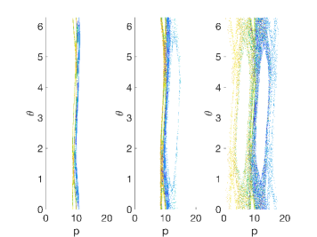
Figure 1 shows three cases to illustrate this point: in which particles are contained to a narrow region; in which particles diffuse freely; and in which particles diffuse very quickly. In Section VIII we shall show that for electrons of the relevant energy of 3 keV in the PFRC-2. Therefore there must be some other phenomenon which allows PFRC-2 particles to cross the purported separatrices between different energies. In Section VII, we will show that, whether or not it is the only such phenomenon, the non-adiabaticity of is a sufficient phenomenon to allow this.
VI The quasiadiabatic behavior of electrons in the PFRC-2
It does not take extreme field curvature or a magnetic null to produce large changes in , a fact known since the 1950shenrich_departure_1956 ; garren_individual_1958 and significantly explored since. Publications describe both the action of a single pass into a non-adiabatic regionhastie_non-adiabatic_1969 ; dykhne_change_1960 ; cohen_nonadiabaticity_1978 and the compounded effect of many such passes.chirikov_stability_1978 ; tagare_motion_1986 ; zelenyi_quasiadiabatic_2013 The name “quasiadiabaticity” is given to the case that particles’ are well-conserved for the majority of their trajectories, but pass through specific regions where their undergo a discrete change in value.zelenyi_quasiadiabatic_2013
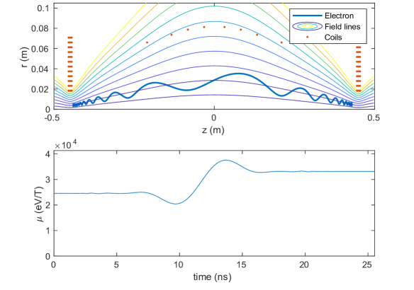
A electron in the PFRC-2, simply following its ballistic trajectory collisionlessly, i.e., without particle-particle collisions, and starting marginally trapped at a medium radius, 6 mm at the nozzle, may readily gain or lose 50 % of its . Figure 2 shows such behavior for a 5.4 keV electron. Calculated changes well reproduce the approximate formulae of Hastie, Taylor, and Hobbs.hastie_non-adiabatic_1969 It is worth noting that the traditional adiabatic parameter, , is small, ca. 0.01, and that the true adiabatic parameter includes contributions from the parallel velocity and the second derivative of the curvature of the magnetic field lines.
This change in is dependent on the gyrophase at the midplane. Similarly to the oscillation phase 1-D map mentioned in Section V, the of a particle also follows a 1-D map which reduces to the standard map, but with different definitions for in Equations 1 and 2. The theory of multiple non-adiabatic changes is what gives the standard map its original name, the Chirikov Map.chirikov_stability_1978
In Section V, to determine the long-time behavior of the energy , we started by determining the difference in the potential oscillation phase between successive increments to the energy, (Equation 7). In this section, to determine the long-time behavior of , we start by determining the difference in the midplane gyrophase between successive increments to the :
| (9) |
| (10) |
is the gyrophase when the particle crosses the midplane the th time. is the difference between gyrophases at successive midplane crossings:
| (11) |
| (12) |
where is the characteristic increment to in one transit of the machine.
VI.1 A note on quasiadiabatic electrons in magnetic mirror machines
The system defined by Equations 9, 10, and 11 are worth studying in their own right. Traditionally, the velocity space of particles in a magnetic mirror is split into two regions: The loss cone of passing particles, for which , and the region of trapped particles, for which . A close examination of these equations reveals that there are actually three regions of velocity space. Another critical value, , defined as that for which , divides the adiabatically trapped region into two regions. is trapped as before; however, is an interesting region in which particles’ are free to diffuse. The particles’ may diffuse as high as , and as low as . The particles’ can not diffuse higher than . If the particle’s diffuses lower than , the particle will be lost on the next bounce.
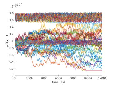
Because particles with may collisionlessly leave the mirror, this region can be thought of as an extended loss cone, which takes several bounces to leave. To test this behavior, we have conducted two Boris-algorithm ensemble simulations, one at a larger than the observed , and one at a smaller than the observed , see Figure 3. These are 3.6 keV particles, at a radius for which their is predicted to be equal to . As depicted in Figure 3, the smaller ensemble does exhibit an upper boundary beyond which it cannot diffuse. The observed is close to . This discrepancy may be due to the inexact nature of the Hastie, Taylor, and Hobbs formulae.
Interestingly, it appears that there are always particles with , no matter how strong and smooth the magnetic field. Observe that, at , the integral in Equation 11 diverges and . Thus there is always some for which , even though this region may be extremely narrow.
For the case of the PFRC-2, it is likely that nearly 100% of the particles accelerated by the electrostatic potential have . This is because these particles begin in the SEC, and so when they enter the CC they are by definition passing. Only those particles whose diffuse into persist for an appreciable time (many bounces).
VII The coupled map of
In Section V, we established that an electrostatic oscillation near one nozzle with the amplitude measured could not heat particles to the 30+ keV measured in the PFRC-2. However, Equation 8 assumes perfect adiabaticity of . In Section VI, we found that the of these particles is extremely mobile. This chaotic behavior may be used to explain how the Fermi-accelerating electrons may circumvent their limit and become heated to very high energies.
By using the formulae of Hastie, Taylor, and Hobbs and Equation 7, we may evaluate an equivalent Chirikov parameter for the effect of on potential oscillation phase:
| (13) |
where is the difference in potential oscillation phase between successive mirror bounces, , where is defined in Equation 7. MHz is the angular frequency of the oscillation (the choice of 200 MHz is described in Section IX), and is evaluated using the formulae of Hastie, Taylor, and Hobbs. For the PFRC-2 magnetic field and 3 keV electrons starting at a medium radius, is numerically evaluated to be , of the same order as .
As the increment in is dependent on gyrophase and the increment in is dependent on oscillation phase , the increment in due to can be modeled as a coupling between two Chirikov maps, (, ) and (, ):
| (14) |
| (15) |
| (16) |
| (17) |
where, recalling from Sections V and VI, is the oscillation phase of the electrostatic oscillation when the particle is incident on the oscillating region for the th time, is the transit time of the particle multiplied by omega on the th bounce (the number of oscillation periods that elapse), is the gyrophase of the particle at the midplane on its nth transit, and is the integral of the transit time multiplied by the local gyrofrequency (the number of gyroperiods that elapse) over the th transit of the machine.
Typical values of for hot electrons in the PFRC-2 are: , per Section V, and , per Section VI. In later paragraphs, we use for illustration purposes. In the case of uncoupled maps (), these values would imply the () map is stable while the () map is unstable. The coupling appears as the last term in Equation 14 and was chosen to be unidirectional from () () since the () map exhibits chaos without the need for coupling. It is this coupling term that is responsible for producing and destroying separatrices in the () map.
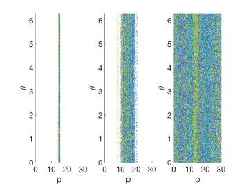
To verify this, we performed numerical iteration of the coupled map defined by Equations 14-17. Results for the () map are plotted in Figure 4. The case that shows diffusion beyond the quasiperiodic initial orbits, and the case that shows much faster diffusion. Thus, while the Chirikov criterion alone indicates that electron energy is constrained to vary only within a narrow band around the initial energy for small , the natural, collisionless changes in in the PFRC-2 are sufficient to allow diffusion.
changes must be greater than to markedly enhance energy diffusivity. The Hastie, Taylor, and Hobbs formula prediction for the PFRC-2 is that the minimum required energy at G is about 1 . For these parameters, the ratio of the electron gyroradius to the field curvature, the traditional adiabatic parameter, at cm of the PFRC-2 midplane is . As observed in the PFRC-2, a low gas pressure, below mT, is required for gas excitation and ionization to not act as large drains on the energy gain. In the PFRC-2, the source of electrons is the capacitively coupled plasma in the Source End Cell (SEC). The EEDF in this SEC plasma satisfiesjandovitz_demonstration_2018 the requirement, hence the strong dependence of the high energy X-ray flux, the proxy for high energy electrons, on SEC RF power.
VIII EEDF evolution equation
In this section, we will assume that the phases of the electrostatic oscillation each time a particle is incident are decorrelated. As we discussed in Section VII, the non-adiabaticity of is sufficient to provide this decorrelation.
The action of random increments to the energy is diffusive,
| (18) |
where is the particle distribution function, is the energy diffusivity, , is the transit time between energy increments, and is the partial derivative with respect to the variable .
Other effects assumed to be important to shaping the EEDF are particle loss rate, , where is the particle loss time, and energy loss, , where is the energy loss rate of a fast electron.
| (19) |
Effects that might contribute to the middle term include (gas) ionization or excitation and X-ray emission. In steady state and far in energy from any sources of particles, the Green’s function solution to this equation is
| (20) |
where
| (21) |
In the limit that , expected at low gas pressure, plugging in the definition of yields
| (22) |
IX Comparison with an experiment
Pulsed, high power ( W) electron beams injected into magnetic mirrors have been used to create microsecond-duration high temperature (10 keV), high density ( cm-3) plasmas, relevant to beam-plasma interaction,smullin_generation_1962 ; alexeff_hot-electron_1963 ; alexeff_beam-plasma_1964 electrostatic turbulence,demirkanov_plasma_1965 ; blinov_plasma_1967 ; alexeff_oscillations_1968 atomic physics processes,alexeff_observation_1964 and nuclear fusion.alexeff_production_1967 ; arzhannikov_new_1988 ; burdakov_plasma_2007 These plasmas are generally observed to have Maxwellian electron energy distribution functions (EEDF) and turbulent electrostatic wave spectra. The accepted mechanism for electron heating is turbulent electrostatic heating along the beam column.
In contrast, in recent studies Swanson_2019 ; jandovitz_demonstration_2018 the PFRC-2 device was run as a steady-state magnetic mirror. Plasma was formed and heated by 50 - 500 W of capacitively-coupled RF power. Run in this mode, the PFRC-2 has more in common with a low-temperature plasma apparatus than with the high-power electron-beam heating experiments. Even so, a “hot” minority component having and was observed in the PFRC-2 central cell (CC). Based on X-ray measurements, some electrons had energies exceeding 30 keV.
A previous paper reported on the measurement in the PFRC-2 SEC of a warm minority component having and .jandovitz_demonstration_2018 That paper also described a near- potential difference between the far end cell, FEC (negative), and the CC (near ground), considerably higher than commonly found in double layer devices.charles_review_2007 That potential spontaneously generates a nearly monoenergetic beam of electrons that propagates from the FEC into the CC.
The parameters of this beam are proper to generate a two-stream instability, creating electrostatic oscillations that are localized in the CC near the FEC. The amplitude of these oscillations, measured to be near 50 Volts, is two orders-of-magnitude lower than the turbulent electrostatic waves in the aforementioned energetic-beam mirror discharges. Moreover, their spectra are sinusoids and harmonics thereof. Nonetheless, in Ref.[Swanson_2019 ] we reported on measurements of a minority “hot” component with a near-Maxwellian EEDF and attributed this population to the low amplitude coherent oscillations. The low value of all potentials (the DC space potentials and the electrostatic oscillations) is very low compared to the 10’s of keV electron energies. This, plus the Maxwellian-like shape of the EEDF, necessitated our consideration of a different mechanism of electron heating. In Ref.[Swanson_2019 ], we presented a heuristic model based on a modified multi-dimensional Fermi-Ulam acceleration process. Herein, we use the methods described in Sections III-VIII to explain the experimental results.
For specificity to the beam-plasma 2-stream instability question, we choose to evaluate the measurement-informed case Swanson_2019 that the beam electrons have a 300 eV drift energy and an effective temperature of 5 eV. This electron velocity distribution function, EVDF, is depicted in Figure 5.
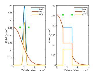
We numerically evaluated the Nyquist theorem criterion for electrostatic mode stability and found this EVDF to be unstable.stix_waves_1992 In the inverse Landau damping limit, the instability condition is also clearly satisfied.
The expected saturation amplitude of this oscillation is calculable from a kinetic model.dewar_saturation_1973 This model roughly agrees with the inverse Landau damping limit of the saturation condition, that is nowhere positive.
By taking the EVDF of the warm electrons as linear around the velocity of the entering beam electrons, we may derive an approximate equation for the amplitude of the oscillation:
| (23) |
where is the peak-to-peak saturation voltage of the oscillation, are the temperature and density of the warm electrons, and are the drift energy and density of the beam electrons. We expect our specific warm-beam plasma system to saturate at 50 according to Equation 23. This is consistent with the measurement made in Ref.[Swanson_2019 ].
The measured spectrum of electrostatic oscillations showed a broad peak around 200 MHz, close to the plasma frequency of the warm population, but it is also close to the cyclotron frequency of electrons at the measured point. Magnetic oscillations were shown to be absent at levels above 0.1 G, that is, the measured signal is purely electrostatic. Nevertheless, the precise nature of the instability is not yet understood.gary_electrostatic_1985
| (24) |
Evaluating at an example energy of 3 keV, we find that the oscillation amplitude V, eV, =3 keV, was measured to be 150 s in our companion paper, ns is calculable from the dimensions of the machine, and eV/s is calculable from the NIST ionization cross sections.kim_NIST_2004 This produces a keV, close to the measured value.
Moreover, evaluating for the measured forcing of the PFRC-2 is possible. Recall from Section VII that , MHz, and transit time is defined in Equation 7, which can be substituted into Equation 8 to obtain . The measured forcing in the PFRC-2 yields , insufficient to allow energy diffusion, supporting our claim that non-conservation of is the cause of the needed de-correlation.
In our companion paper, we verify the expected dependence on by increasing the neutral gas density in the FEC and so increasing beam current. The expected linear relationship between and is measured.
We also verified the expected dependence on by increasing the neutral gas density in the CC, increasing collision-induced particle loss. Agreement was again obtained between the measured and the measured .
Because of the agreement between Equation 24 and the measured temperatures in our companion paper, we propose the diffusion of particle energy under the influence of a spontaneous two-stream electrostatic instability as the mechanism for accelerating electrons to the high temperatures seen in the PFRC-2.
X Summary
In this paper, we have described a novel plasma heating process which we believe to be heating warm electrons to 3 keV temperatures in the PFRC-2, as measured in a companion publication.Swanson_2019 It is Fermi acceleration from a localized, sinusoidal, electrostatic fluctuation. This arises from two-stream instability from a spontaneously generated beam, caused by ionization downstream of a potential drop. We have given a simple model for the amplitude of the oscillation based on the inverse-Landau-limit saturation criterion, . We have shown via a diffusive-loss model that this localized oscillation, combined with the natural motion of the particles in the magnetic mirror field, causes the particles to assume a roughly Maxwellian EEDF with a predicted temperature which agrees with the measured.
However, periodic forcing alone would not allow acceleration to the high energies observed in the PFRC-2, due to the existence of phase-space separatrices in maps which reduce to the Standard Map. We have shown a sufficient phenomenon to break this separatrix, the phase-decorrelation effect of the natural non-adiabatic mobility of the magnetic moment, . We showed this by implementing a coupled map and by a numerical iteration thereof. Finally, we have presented evidence that this same non-adiabaticity of could be leading to another anomalous measurement in the PFRC-2, the high density of warm particles. We believe this occurs when passing particles equilibrate with a population of particles which are neither absolutely trapped nor passing, that exist in a chaotic region around the loss cone which has previously been described.
Acknowledgements
We are grateful to Princeton Fusion Systems for their support of C. Galea. This work was supported by the U.S. Department of Energy under contract number DE-AC02-09CH11466. The United States Government retains a non-exclusive, paid-up, irrevocable, world-wide license to publish or reproduce the published form of this manuscript, or allow others to do so, for United States Government purposes.
Data Availability Statement
The figures in this paper are openly available.
References
- (1) Henrich, L. R., “Departure of Particle Orbits from the Adiabatic Approximation,” Proc. Conf. on Thermonuclear Reactions, United States Atomic Energy Comission, Gatlinburg, Tennessee, 1956.
- (2) Garren, A. A., Riddell, R. J., Smith, L., Bing, G., Roberts, J. E., Northrop, T. G., and Henrich, L. R., “Individual particle motion and the effect of scattering in an axially symmetric magnetic field,” Journal of Nuclear Energy (1954), Vol. 7, No. 3-4, Sept. 1958, pp. 283–284.
- (3) Tagare, S. G., “Motion of charged particles in an axisymmetric magnetic mirror,” Physical Review A, Vol. 34, No. 2, Aug. 1986, pp. 1587–1590.
- (4) Zelenyi, L. M., Neishtadt, A. I., Artemyev, A. V., Vainchtein, D. L., and Malova, H. V., “Quasiadiabatic dynamics of charged particles in a space plasma,” Physics-Uspekhi, Vol. 56, No. 4, 2013, pp. 347.
- (5) Hastie, R. J., Hobbs, G. D., and Taylor, J. B., “Non-Adiabatic Behaviour of Particles in Inhomogeneous Magnetic Fields,” Plasma Physics and Controlled Nuclear Fusion Research. Proceedings of the Third International Conference on Plasma Physics and Controlled Nuclear Fusion Research. Vol. I, 1969.
- (6) Cohen, R. H., Rowlands, G., and Foote, J. H., “Nonadiabaticity in mirror machines,” The Physics of Fluids, Vol. 21, No. 4, April 1978, pp. 627–644.
- (7) Zaslavsky, G. M. and Chirikov, B. V., “Fermi acceleration mechanism in the one-dimensional case,” Dokl. Akad. Nauk, Vol. 159, No. 2, 1964, pp. 306–309.
- (8) Chirikov, B. V., “Stability of the Motion of a Charged Particle in a Magnetic Confinement System,” Sov. J. Plasma Phys. (Engl. Transl.); (United States), Vol. 4:3, May 1978.
- (9) Delcourt, D. C., Martin, R. F., and Alem, F., “A simple model of magnetic moment scattering in a field reversal,” Geophysical Research Letters, Vol. 21, No. 14, July 1994, pp. 1543–1546.
- (10) Fermi, E., “On the Origin of the Cosmic Radiation,” Physical Review, Vol. 75, No. 8, April 1949, pp. 1169–1174.
- (11) Ulam, S., “On Some Statistical Properties of Dynamical Systems,” Proceedings of the Fourth Berkeley Symposium on Mathematical Statistics and Probability, University of California Press, 1961, p. 315, Google-Books-ID: OZF2WtUKB44C.
- (12) Lieberman, M. A. and Lichtenberg, A. J., “Stochastic and Adiabatic Behavior of Particles Accelerated by Periodic Forces,” Physical Review A, Vol. 5, No. 4, April 1972, pp. 1852–1866.
- (13) Lichtenberg, A. J., Lieberman, M. A., and Cohen, R. H., “Fermi acceleration revisited,” Physica D: Nonlinear Phenomena, Vol. 1, No. 3, Sept. 1980, pp. 291–305.
- (14) Karlis, A. K., Papachristou, P. K., Diakonos, F. K., Constantoudis, V., and Schmelcher, P., “Hyperacceleration in a Stochastic Fermi-Ulam Model,” Physical Review Letters, Vol. 97, No. 19, Nov. 2006, pp. 194102.
- (15) Chirikov, B. V., “A universal instability of many-dimensional oscillator systems,” Physics Reports, Vol. 52, No. 5, May 1979, pp. 263–379.
- (16) Swanson, C. and Cohen, S. A., “Spontaneous multi-keV electron generation in a low-RF-power axisymmetric mirror machine,” Physics of Plasmas, Vol. 26, 2019, pp. 060701.
- (17) Schrittwieser, R., Axnas, I., Carpenter, T., and Torven, S., “Observation of double layers in a convergent magnetic field,” IEEE Transactions on Plasma Science, Vol. 20, No. 6, Dec. 1992, pp. 607–613.
- (18) Swanson, C., Measurement and Characterization of Fast Electron Creation, Trapping, and Acceleration in an RF-coupled, High-mirror-ratio Magnetic Mirror, Doctoral thesis, Princeton University, Princeton, New Jersey, USA, 2018.
- (19) Dykhne, A. M. and Pokrovskii, V. L., “Change of the Adiabatic Invariant of a Paricle in a Magnetic Field,” Journal of Experimental and Theoretical Physics, Vol. 39, No. 2, 1960, pp. 373.
- (20) Cohen, R. H., Rowlands, G., and Foote, J. H., “Nonadiabaticity in mirror machines,” Physics of Fluids (1958-1988), Vol. 21, No. 4, April 1978, pp. 627–644.
- (21) Jandovitz, P., Swanson, C., Matteucci, J., Oliver, R., Pearcy, J., and Cohen, S. A., “Demonstration of fast-electron populations in a low-pressure, low-power, magnetized RF plasma source,” Physics of Plasmas, Vol. 25, No. 3, March 2018, pp. 030702.
- (22) Smullin, L. D. and Getty, W. D., “Generation of a Hot, Dense Plasma by a Collective Beam-Plasma Interaction,” Physical Review Letters, Vol. 9, No. 1, July 1962, pp. 3–6.
- (23) Alexeff, I., Neidigh, R. V., Peed, W. F., Shipley, E. D., and Harris, E. G., “Hot-Electron Plasma by Beam-Plasma Interaction,” Physical Review Letters, Vol. 10, No. 7, April 1963, pp. 273–276.
- (24) Alexeff, I., Neidigh, R. V., and Peed, W. F., “Beam-Plasma Interaction Experiments and Diagnostics,” Physical Review, Vol. 136, No. 3A, Nov. 1964, pp. A689–A695.
- (25) Demirkanov, R. A., Gevorkov, A. F., and Popov, A. F., “Plasma Heating under Beam Instability Conditions,” Plasma Physics and Controlled Nuclear Fusion Research. Proceedings of the Third International Conference on Plasma Physics and Controlled Nuclear Fusion Research, 1965.
- (26) Blinov, P. I., Zakatov, L. P., Plakhov, A. G., Chikin, R. V., and Shapkin, V. V., “Plasma Heating by and Electric Beam in a Magnetic Mirror Machine,” Soviet Physics JETP, Vol. 25, No. 3, Sept. 1967, pp. 439.
- (27) Alexeff, I., Guest, G. E., Montgomery, D., Neidigh, R. V., and Rose, D. J., “Oscillations Present in Plasma-Electron Heating by an Electron Beam,” Physical Review Letters, Vol. 21, No. 6, Aug. 1968, pp. 344–347.
- (28) Alexeff, I. and Neidigh, R. V., “Observation of Burnout in a Steady-State Plasma,” Physical Review Letters, Vol. 13, No. 6, Aug. 1964, pp. 179–181.
- (29) Alexeff, I., Jones, W. D., and Neidigh, R. V., “Production of d-d Reactions by Beam-Plasma Interaction in the Steady State,” Physical Review Letters, Vol. 18, No. 25, June 1967, pp. 1109–1112.
- (30) Arzhannikov, A. V., Burdakov, A. V., Kapitonov, V. A., Koidan, V. S., Konyukhov, V. V., Lebedev, S. V., Mekler, K. I., Nikolaev, V. S., Postupaev, V. V., Ryutov, D. D., Shcheglov, M. A., Sinitsky, S. L., Voropaev, S. G., and Vyacheslavov, L. N., “New experimental results on beam-plasma interaction in solenoids,” Plasma Physics and Controlled Fusion, Vol. 30, No. 11, 1988, pp. 1571.
- (31) Burdakov, A., Arzhannikov, A. V., Astrelin, V., Ivanov, I., Ivantsivsky, M., Koidan, V., Mekler, K., Polosatkin, S., Postupaev, V. V., Rovenskikh, A. F., Sinitsky, S. L., and Sulyaev, Y. S., “Plasma Heating and Confinement in GOL-3 Multi Mirror Trap,” Fusion Science and Technology, Vol. 51, No. 2T, Feb. 2007, pp. 106–111.
- (32) Charles, C., “A review of recent laboratory double layer experiments,” Plasma Sources Science and Technology, Vol. 16, No. 4, 2007, pp. R1.
- (33) Stix, T. H., Waves in Plasmas, AIP-Press, 1992.
- (34) Dewar, R. L., “Saturation of kinetic plasma instabilities by particle trapping,” The Physics of Fluids, Vol. 16, No. 3, March 1973, pp. 431–435.
- (35) Gary, S. P., “Electrostatic instabilities in plasmas with two electron components,” Journal of Geophysical Research: Space Physics, Vol. 90, No. A9, 1985, pp. 8213–8221.
- (36) Kim, Y.-K., Irikura, K., Rudd, M., Ali, M., Stone, P., Chang, J., Coursey, J., Dragoset, R., Kishore, A., Olsen, K., Sansonetti, A., Wiersma, G., Zucker, D., and Zucker, M., “NIST Electron-Impact Ionization Cross Section for Ionization and Excitation Database (version 3.0),” Tech. rep., National Institute of Standards and Technology, Gaithersburg, MD, USA, 2004.