Optimal Design of Coatings for Mirrors of Gravitational Wave Detectors: Analytic Turbo Solution via Herpin Equivalent Layers
Abstract
In this paper, an analytical solution to the problem of optimal dielectric coating design of mirrors for gravitational wave detectors is found. The technique used to solve this problem is based on Herpin’s equivalent layers, which provide a simple, constructive, and analytical solution. The performance of the Herpin-type design exceeds that of the periodic design and is almost equal to the performance of the numerical, non-constructive optimized design obtained by brute force. Note that the existence of explicit analytic constructive solutions of a constrained optimization problem is not guaranteed in general, when such a solution is found, we speak of turbo optimal solutions.
I Introduction
The development of optimized coatings for the end test-masses of the gravitational wave interferometers is one of the important goals to be achieved for improving the sensitivities of gravitational wave detectors [1, 2]. Indeed, the coating Brownian noise is the most relevant source of noise in the band of interest for astrophysical observation. To reduce this source of noise, researchers can act by using different materials with the best properties for the mirrors, optimizing the interferometer’s laser beam, lowering the temperature to cryogenic values, and finally acting on the coating design. Unfortunately, there are not many glassy materials that satisfy the optical requirements necessary for gravitational wave detectors, the improvement of the laser beam would require a rethinking of the whole interferometer cavity as well as make this cavity cryogenic (see the papers [3, 4, 5] for a review on the subject).
In this work, we explore the possibility of optimizing the design of the mirrors by acting on the thicknesses of the layers that form the coating, with the materials currently available. Although coatings made of multiple materials [6, 7, 8] (obtained, in some cases, from cascades of binary designs) have been recently proposed, further study of binary coating theory provides the theoretical tools to understand more complex approaches.
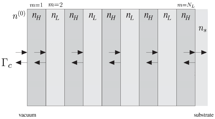
It is well known [9] that the electrodynamics of multilayers structures, like those depicted in Figure 1, can be described in a semi-analytic way with the method of the characteristic matrices of the layers (also called transmission matrices [10]). The characteristic matrix of the -th layer can be written [11, 12]:
| (1) |
where is the electric phase, and are the free space wavelength and the layer thickness, respectively, and is the complex refractive index. Here is the extinction coefficient, which for the considered materials will be negligible (i.e., ).
The optical response of the whole coating (i.e., the transmittance) can be computed from the multilayer characteristic matrix,
| (2) |
where is the total number of layers numbered from the vacuum to the substrate as illustrated in Figure 1. To write Equation (2) we use the property that the characteristic matrix of a sequence of layers is the product of the characteristic matrices of the individual layers.
The transmittance calculation is done in two steps, first the equivalent reflection index of the multi-layer structure, and then the reflection coefficient at the vacuum interface are computed. The complex reflection coefficient at the vacuum/coating interface is given by:
| (3) |
where is the effective refractive index of the whole multilayer structure,
| (4) |
The power transmittance at the vacuum/coating interface is . In the case of binary coating we have:
| (5) |
These multilayer structures are made of alternating high and low refractive indexes deposited on a substrate of refractive index . The coefficients and are the mechanical losses and and are the Young moduli of the two materials. Let us also introduce the specific noise coefficients that will be used in the following:
| (6) |
where is the (assumed Gaussian) laser-beam waist. Thermal noise in gravitational detectors is the most important limitation for their operation. We refer the reader to the works in [13, 14, 15] for an exhaustive description of the problem and the proposed solutions [16, 17] in the operating observatory Virgo [1] and LIGO [2].
A straightforward formulation of the coating optimization problem for the design of low noise dielectric mirror can be:
| (7) | ||||||
| subject to |
where the constraint transmittance should be a few parts per million (ppm), typically ppm.
Defining the normalized loss angle and introducing the normalized physical length , where is the free-space wavelength of the laser, we have for binary coatings:
| (8) |
where summation (resp. ) is on the even (resp. odd) integer such that . The noise ratio coefficient in Equation (8), i.e., , can be explicitly written for binary coating as:
| (9) |
In the case where the refractive index is the same as that of the substrate material (as in current gravitational wave detectors) is an odd number. The choice of an even would lead to a configuration with the rightmost layer (near the substrate) made of low refractive index material (the same as the substrate) that would increase noise without having any effect on reflectivity. The search space is defined by the inequalities for odd and for even . An alternative and equivalent way to formulate the optimization problem (as shown in [18]) is
| (10) | ||||||
| subject to |
where is a prescribed maximum allowed loss angle.
II The Herpin Equivalent Layer Optimization Problem
According to Herpin’s equivalent layer theorem [19] a symmetrical multilayer stack (i.e., a palindrome sequence of dielectric thin films) is equivalent to a single layer. This theorem is based on the fact that the two elements on the main diagonal of the characteristic matrix of any palindromic sequence of materials are equal.
In this paper, we consider an equivalent Herpin layer that consists of three physical layers arranged in an -type sequence. According to the general theorem, this sequence must be dielectrically and geometrically symmetric, so both materials and layer thicknesses must be palindromic. Thus denoting by and the normalized lengths of the layers and respectively, below are shown, using a simple computation, the relevant elements of the transmission matrix of the considered virtual layer :
| (11) |
| (12) |
It can be verified by inspection, and this is also the main result of Herpin’s theorem, that , and because of the unitary constraint on the determinant of the characteristic matrix , the last element is uniquely determined by solving the following equation w.r.t. :
| (13) |
To understand the reasons that lead to formulating the present analytical solution, we summarize the results of the papers [18, 20]. In the paper [18], a multi-objective optimization (with the BorgMOEA algorithm [21]) without a priori hypothesis was applied to the problem of general optimization of binary coatings for gravitational wave detectors mirrors.
It has been shown in [18] that the Pareto front remains the same whether one sets up a code that solves problem (7) or implements problem (10), so the two formulations considered are equivalent. Moreover, in the same paper we show that the optimal design is made by the following sequences of layers . The sequence of thicknesses associated with this solution is given by , where in general , . This solution is periodic except for the first and last layers, and that is why the solution has been called periodic with initial and final tweaking. Furthermore satisfy an approximate Bragg condition .
In the paper [20], a very simple periodic solution was studied and experimentally validated [22]. In these articles the tweaking procedure has been considered but only as a possible second step of improvement of the periodic design, considering the thicknesses of the innermost layers fixed to the values calculated in the first step. This solution approximates that which would be found by optimizing on all four layers simultaneously, that is implemented in [18].
Finally, in the paper [18] (see Equation (20) therein) it has been shown that the Pareto front of the optimized solutions is placed close to the transmittance versus thermal noise line relative to a suitable (virtual) quarter-wave design.
So far, we have mentioned almost exhaustively all the existing literature on the coating optimization problem. For the sake of completeness, although not completely relevant, let us mention [23] which proposes a physical-mathematical approach to the computation of the best periodic design, we emphasize that the method is not based on solving an optimization problem.
Taking into account the hints introduced above, we assume that the optimal solution is of the form where is an equivalent Herpin layer, as introduced above, and is a quarter-wave layer. We note that in these designs the last layer is of type , i.e., it is a virtual layer consisting of an sequence. Additionally, in this case, the last physical layer (near the substrate) of type in the last virtual layer is not considered because it is made of the same material as the substrate and does not contribute to the dielectric contrast (actually, the last interface does not exist, it is fictitious).
We are now able, from all these ansatz introduced above, to reformulate the optimization problem as follows:
| (14) | ||||||
| subject to |
here is the set of quarter wavelength transmission matrix and is determined by the normalized physical length , and . We have
| (15) |
where is the normalized quarter wavelength thickness of layer. The condition can be explicated by requiring i.e.,
| (16) |
III Numerical Results
In this section, we compute the Pareto front of the three competing designs , i.e., the proposed design method in Equation (14), the periodic design [20] and the fully (brute force) optimized design [18]. Table 1 is used as a reference for the physical parameters of the and materials.
| Coating | Substrate |
|---|---|
| (amorphous Ti-doped Ta2O5 ) | (bulk crystalline SiO2) |
| (SiO2) | |
| GPa | |
| GPa | |
| GPa | |
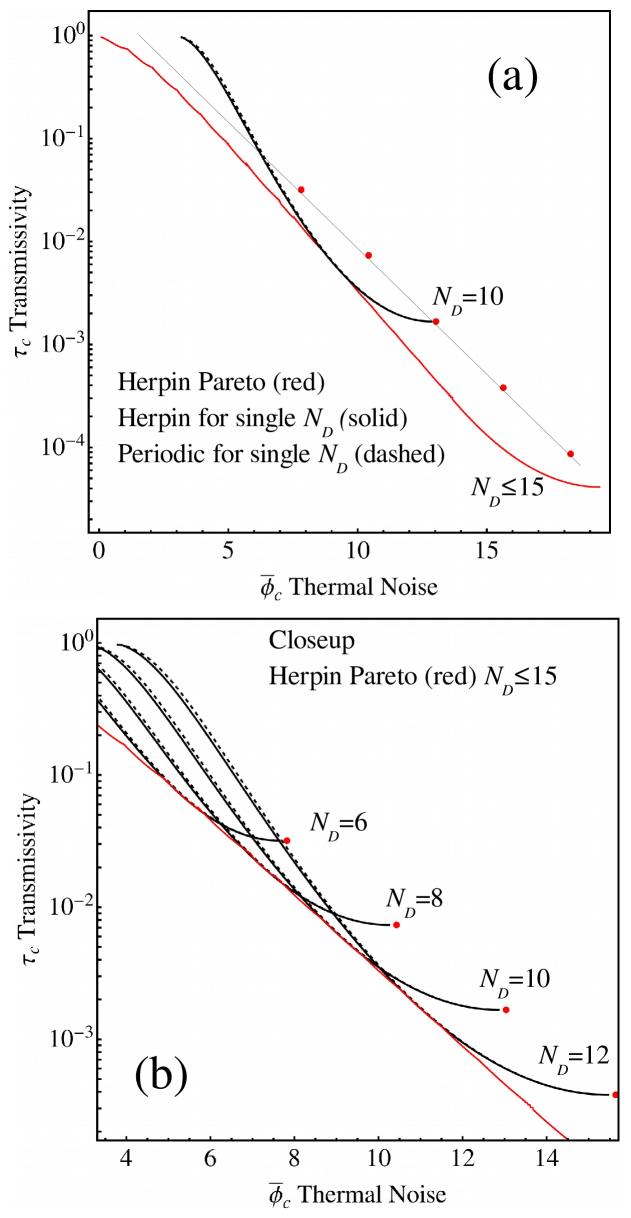
In Figure 2a the Pareto front of the problem (14) where is shown in red on a log-linear scale as a function of the dimensionless quantity . The continuous black curve represents the Pareto front again for problem (14) but with kept fixed. Finally, for fixed the dashed curves show the Pareto front of the optimal periodic doublet design. 0
In Figure 2b, a close-up of the central area of the Figure 2a is shown along with several Pareto fronts of Herpin (continuous curves) and periodic (dashed curves) designs.
From the analysis of Figure 2, it is clear that Herpin’s design generates a Pareto front that consists of several bumps (a bumpy curve). This behavior had already been observed in the brute force solution given by the BorgMOEA method used in the paper [18]. This figure reveals that the various bumps of the complete Pareto front are parts of the Pareto curves with fixed that intersect each other (see Figure 2b).
Moreover, as will be more evident later, we note that the periodic designs are always worse than Herpin’s. Let us take a closer look at this result in Figure 3 to better illustrate it. The Pareto front of the periodic synthesis of the doublet (respectively of the BorgMoea) will be called with (respectively with ).
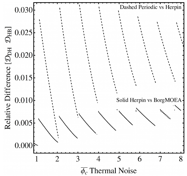
In Figure 3 the following normalized differences
| (17) |
are displayed. To be precise, in Figure 3 the function is the dashed curve while is the continuous black one. By inspection of the figure, it is clear that both the two normalized differences are positive and have discontinuity points in the cusps that separate the different bumps in the Pareto front curves. The value of these functions remains limited (about 3% for and about 0.9% for ) even in the region with the highest noise (i.e., low transmittance), which is that of interest for gravitational applications.
In this connection, the values of the normalized thermal noise (on the Pareto front) for the three analyzed methods are reported in Table 2 for fixed values of the transmittance constraint. Some values of the transmittance constraint are shown in the first column of Table 2 together with the value of giving the optimal solutions for all the three analyzed design methods, i.e., periodic doublets, brute force BorgMOEA and Herpin design. The values of the computed minimum normalized thermal noise are reported in the other columns of the Table.
This table confirms the results of Figure 3, i.e., even in the zone of very low transmittance, the Herpin-like semi-analytic method is the one that comes closest to the minimum value obtained with brute force, for which there is no simple constructive recipe.
| Parameters | |||||
|---|---|---|---|---|---|
| Periodic doublet | Borg MOEA | Herpin | |||
|
|
19.597 | 19.560 | 19.573 | ||
|
|
18.826 | 18.786 | 18.803 | ||
|
|
16.115 | 16.076 | 16.091 | ||
|
|
15.345 | 15.300 | 15.317 |
IV Conclusions
The production and characterization of layered systems with dimensions of hundreds of nanometers or less, to be used as highly reflective surfaces [24, 25] is a problem of great interest for improving the operation of gravitational wave antennas [1, 2]. Herpin’s theorem allows obtaining an equivalent stratified material, consisting of three layers arranged in a palindrome sequence, which mimic exactly a quarter-wave layer. In this paper, these quarter-wave equivalent layers are used in conjunction with normal (quarter-wave) layers made of low refractive index material, to produce optimized designs of coatings. The method reduces to an optimization problem with two independent parameters, namely the number of equivalent layers and the normalized thickness of one of the materials defining the equivalent layer. Thus, a turbo solution to the problem (i.e., an explicit analytic constructive solution) can be found in a very simple way. Such a solution is closer to that obtained with the BorgMOEA method [18] than the doublet periodic one [20]. The prediction made in a previous article [18], namely that the BorgMOEA brute force design should be close to a virtual quarter-wave design, is fully confirmed. Indeed, in this paper, an explicit semi-analytic quarter-wave design is found, even of simple physical interpretation. The limitation of the present study is that it only deals with the case of binary coatings. The authors are convinced that with a similar philosophy it is possible to derive optimal coating designs even in the case of layers made with three (possibly dissipative) materials, or even made with nano-layered [26] materials.
Acknowledgments
This work has been partially supported by INFN through the projects Virgo and Virgo—ET. The author is grateful for the discussion and suggestions received from the Virgo Coating Research and Development Group and the Optics Working Group of the LIGO Scientific Collaboration. Special thanks to I.M. Pinto for his constant interest and encouragement in publishing this article.
References
- [1] Virgo http://www.virgo.infn.it
- [2] LIGO http://www.ligo.caltech.edu
- [3] The LIGO Scientific Collaboration. Advanced LIGO. Class. Quantum Gravity 2015, 32, 074001.
- [4] Acernese, F.; Agathos, M.; Agatsuma, K.; Aisa, D.; Allemandou, N.; Allocca, A.; Amarni, J.; Astone, P.; Balestri, G.; Ballardin, G.; et al. Advanced Virgo: A second-generation interferometric gravitational wave detector. Class. Quantum Gravity 2015, 32, 024001.
- [5] The KAGRA Scientific Collaboration. Overview of KAGRA: Calibration, detector characterization, physical environmental monitors, and the geophysics interferometer. Prog. Theor. Exp. Phys. 2021, 2021, 05A102.
- [6] Yam, W.; Gras, S.; Evans, M. Multimaterial coatings with reduced thermal noise. Phys. Rev. D 2015, 91, 042002.
- [7] Steinlechner, J.; Martin, I.W.; Hough, J.; Kruger, C.; Rowan, S.; Schnabel, R. Thermal noise reduction and absorption optimization via multimaterial coatings. Phys. Rev. D 2015, 91, 042001.
- [8] Pierro, V.; Fiumara, V.; Chiadini, F.; Granata, V.; Durante, O.; Neilson, J.; Di Giorgio, C.; Fittipaldi, R.; Carapella, G.; Bobba, F.; et al. Ternary quarter wavelength coatings for gravitational wave detector mirrors: Design optimization via exhaustive search. Phys. Rev. Res. 2021, 3, 023172.
- [9] Strutt, J.W. On the Refection of Light from a Regularly Stratified Medium. Proc. R. Soc. Lond. Ser. A Contain. Pap. A Math. Phys. Character 1917, 93, 565–577.
- [10] Abelès, F. La théorie générale des couches minces. J. Phys. Radium 1950, 11, 307–309.
- [11] Born , M.; Wolf , E. Principles of Optics: Electromagnetic Theory of Propagation, Interference and Diffraction of Light, 7th ed.; Cambridge University Press: Cambridge, UK, 1999.
- [12] Orfanidis, S.J. Electromagnetic Waves and Antennas. Web Book. Available online: https://www.ece.rutgers.edu/~orfanidi/ewa/ (accessed on 8 Dec. 2021).
- [13] Harry, G.; Bodiya, T.P.; DeSalvo R. Optical Coatings and Thermal Noise in Precision Measurements, 1st ed.; Cambridge University Press: Cambridge, UK, 2012.
- [14] Abernathy, M.R.; Liu, X.; Metcalf, T.H. An overview of research into low internal friction optical coatings by the gravitational wave detection community. Mater. Res. 2018, 21, e20170864.
- [15] Flaminio, R.; Franc, J.; Michel, C.; Morgado, N.; Pinard, L.; Sassolas, B. A study of coating mechanical and optical losses in view of reducing mirror thermal noise in gravitational wave detectors. Class. Quantum Gravity 2010, 27, 084030.
- [16] Pinard, L.; Sassolas, B.; Flaminio, R.; Forest, D.; Lacoudre, A.; Michel, C.; Montorio, J.L.; Morgado, N. Toward a new generation of low-loss mirrors for the advanced gravitational waves interferometers. Opt. Lett. 2011, 36, 1407–1409.
- [17] Pinard, L.; Michel, C.; Sassolas, B.; Balzarini, L.; Degallaix, J.; Dolique, V.; Flaminio, R.; Forest, D.; Granata, M.; Lagrange, B.; et al. Mirrors used in the LIGO interferometers for first detection of gravitational waves. Appl. Opt. 2017, 56, C11.
- [18] Pierro, V.; Fiumara, V.; Chiadini, F.; Bobba, F.; Carapella, G.; Di Giorgio, C.; Durante, O.; Fittipaldi, R.; Mejuto Villa, E.; Neilson, J.; et al. On the performance limits of coatings for gravitational wave detectors made of alternating layers of two materials. Opt. Mater. 2019, 96, 109269.
- [19] Herpin, A.; Cabannes, N.J. Optique Electromagnétique—Calcul du Pouvior Réflecteur dun Systeme Stratifie Quelconque. C. R. Acad. Sol. 1947, 225, 182–183.
- [20] Agresti, J.; Castaldi, G.; DeSalvo, R.; Galdi, V.; Pierro, V.; Pinto, I.M. Optimized multilayer dielectric mirror coatings for gravitational wave interferometers. Proc. SPIE 2006, 6286, 628608.
- [21] Hadka , D.; Reed , P.M. Borg: An Auto-Adaptive Many-Objective Evolutionary Computing Framework. Evol. Comput. 2013, 21, 231–259.
- [22] Villar, A.E.; Black, E.D.; DeSalvo, R.; Libbrecht, K.G.; Michel, C.; Morgado, N.; Pinard, L.; Pinto, I.M.; Pierro, V.; Galdi, V.; et al. Measurement of thermal noise in multilayer coatings with optimized layer thickness. Phys. Rev. D 2010, 81, 122001.
- [23] Kondratiev, N.M.; Gurkovsky, A.G.; Gorodetsky, M.L. Thermal noise and coating optimization in multilayer dielectric mirrors. Phys. Rev. D 2011, 84, 022001.
- [24] Durante, O.; Di Giorgio, C.; Granata, V.; Neilson, J.; Fittipaldi, R.; Vecchione, A.; Carapella, G.; Chiadini, F.; DeSalvo, R.; Dinelli, F.; et al. Emergence and Evolution of Crystallization in TiO2 Thin Films: A Structural and Morphological Study. Nanomaterials 2021, 11, 1409.
- [25] Ţălu, Ş. Micro and Nanoscale Characterization of Three Dimensional Surfaces. Basics and Applications; Napoca Star Publishing House: Cluj-Napoca, Romania, 2015.
- [26] Pan, H.W.; Wang, S.J.; Kuo, L.; Chao, S.; Principe, M.; Pinto, I.M.; DeSalvo, R. Thickness-dependent crystallization on thermal anneal for titania/silica nm-layer composites deposited by ion beam sputter method. Opt. Express 2014, 22, 29847–29854.