A Raman heterodyne determination of the magnetic anisotropy for the ground and optically excited states of Y2SiO5 doped with Sm3+
Abstract
We present the full magnetic g tensors of the 6H5/2Z1 and 4G5/2A1 electronic states for both crystallographic sites in Sm3+:Y2SiO5, deduced through the use of Raman heterodyne spectroscopy performed along 9 different crystallographic directions. The maximum principle g values were determined to be 0.447 (site 1) and 0.523 (site 2) for the ground state and 2.490 (site 1) and 3.319 (site 2) for the excited state. The determination of these g tensors provide essential spin Hamiltonian parameters that can be utilized in future magnetic and hyperfine studies of Sm3+:Y2SiO5, with applications in quantum information storage and communication devices.
I Introduction
Lanthanide-doped insulating crystals serve as appealing candidates for the realization of quantum information storage and communication devices. Recently, demonstrations of optical quantum memories and quantum gate implementations have been achieved [1, 2, 3, 4, 5]. Y2SiO5 is the host of choice in the realization of these devices owing to the low nuclear spins of the constituent ions, with 89Y being the only isotope with a non-zero nuclear spin (I = 1/2) that naturally occurs with considerable abundance [6, 7]. This reduces the spin-flips induced by the neighbouring ions leading to the long coherence times exhibited by such materials, with observations of coherence times exceeding 1 minute for Pr3+:Y2SiO5 and 6 hours for Eu3+:Y2SiO5 [8, 9]. These coherence times were obtained through the use of the Zero-First-Order-Zeeman (ZEFOZ) technique which utilizes an external magnetic field to minimize dephasing induced by spin flips on neighbouring host lattice ions. The field points at which this occurs are known as ZEFOZ points, which are avoided crossings of the hyperfine levels that exist within the Zeeman-hyperfine structure of lanthanide-doped materials. ZEFOZ points are difficult to find experimentally but can be computationally predicted, for example, through the use of the spin Hamiltonian [10]. The studies that resulted in the observed coherence times were enabled by previous studies that determined spin Hamiltonian parameters for Pr3+:Y2SiO5 and Eu3+:Y2SiO5 [8, 9, 10, 11, 12].
Kramers systems provide an appealing alternative to non-Kramers ions in applications of quantum information storage and communication devices owing to ions such as Sm3+ and Er3+ having large hyperfine splittings relative to Pr3+ and Eu3+ [13, 8, 9]. This allows for larger memory bandwidths within these hyperfine transitions whilst still obtaining reasonably long coherence times. Previously, a hyperfine coherence time of 1.3 s was obtained for Er3+:Y2SiO5 through the use of high magnetic fields strengths [3]. Furthermore, studies have obtained hyperfine coherence times of 1 ms and 1.48 ms for Yb3+:Y2SiO5 and Er3+:Y2SiO5 respectively without the need of applying an external magnetic field [14, 15]. These studies were enabled by previously determined spin Hamiltonian parameters [16, 17]. In particular, Sm3+:Y2SiO5 provides a not yet investigated alternative in such applications thanks to the small ground state g values, which results in a relative insensitivity to magnetic field fluctuations. Additionally, Sm3+ has a multitude of isotopes with 71.2 % of all naturally occurring Sm3+ possessing zero nuclear spin, and two isotopes, 147Sm and 149Sm, with natural abundances of 15.0 % and 13.8 % respectively, both have a nuclear spin of 7/2. This gives rise to the possibility of multiple ZEFOZ points within the Sm3+:Y2SiO5 system for both of the non-zero nuclear spin isotopes [18].
We report on the determination of the magnetic g tensors of the 6H5/2Z1 and 4G5/2A1 states for both sites of Sm3+:Y2SiO5 through the use of Raman heterodyne spectroscopy, focusing on the nuclear spin zero isotopes of Sm3+. The 4G5/2A1 state, located at 560 nm, is of particular interest as it is the only emitting state in Sm3+:Y2SiO5, owing to non-radiative relaxation between all other states, and is readily accessible with conventional visible lasers [19]. Raman heterodyne spectroscopy is a widely used spectroscopic technique used in probing the hyperfine structure of lanthanide-doped systems, as first demonstrated in the detection of nuclear magnetic resonance of Pr3+:LaF3 [20, 21]. Recent studies have shown the ability to characterize many non-Kramers in addition to Kramers systems through the determination of spin Hamiltonian parameters [22, 12, 23]. The ability to determine such spin Hamiltonian parameters, including the g tensors determined in this study, are essential precursors in the development of quantum information storage and communication devices.
II Experimental
Y2SiO5 is a monoclinic silicate crystal having space group C [24]. The lattice constants of Y2SiO5 are a = 10.4103 Å, b = 6.7212 Å, c = 12.4905 Å, and = 102∘39’. Here the crystallographic b axis corresponds to the C2 rotation axis and the crystallographic a and c axes are located in the mirror plane which is perpendicular to the crystallographic b axis. Each unit cell of Y2SiO5 is composed of eight Y2SiO5 molecules, with each molecule containing two substitutional Y3+ sites, denoted site 1 and site 2. Both of these sites have C1 symmetry and are distinguished by their coordination numbers of six and seven respectively. Following the convention of Li et al. we define the optical extinction axes as D1 and D2 which are located in the a-b mirror plane and are perpendicular to each other in addition to the crystallographic b axis [25]. Additionally, each site of Y2SiO5 also contains two sub-sites which are related by a 180∘ rotational symmetry and respond differently when a magnetic field is applied outside of the D1-D2 plane or the b axis [26].
The sample used in this study was grown in the X2 phase of Y2SiO5 using the Czochralski process by Scientific Materials Inc. (Bozeman, USA), with a Sm3+ dopant concentration of 0.5 molar %. The crystal had dimensions of (5.1 0.1) mm along the D1 axis, (4.9 0.1) mm along the D2 axis, and (6.0 0.2) mm along the crystallographic b axis.
In order to perform Raman heterodyne spectroscopy, the sample was attached to an aluminium sample holder that also included a 4 loop copper coil. This coil allows RF coupling to the sample up to approximately 70 MHZ.
Raman heterodyne spectroscopy involves coupling a RF excitation source to an optical source supplied by a single frequency laser. The experimental setup is given in Figure 1 a). Upon the application of a magnetic field, the Kramers degeneracy is removed allowing the ground and excited states to each split into two Zeeman states. Figure 1 b) depict the energy level diagram relevant to Raman Heterodyne spectroscopy.
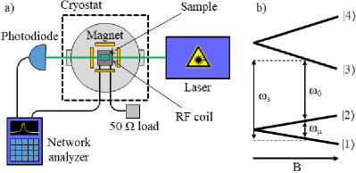
The sample holder was screwed into a cryostat which allowed the sample to be cooled to 3.2 K. Within the cryostat, located around the sample holder is a HTS-110 Ltd. liquid nitrogen cooled superconducting vector magnet.
The RF field was provided by a network analyzer. When the RF field is resonant to a Zeeman transistion, the resulting optical field leaving the sample is composed of the two optical frequencies, and , with a beat frequency of . This signal was detected by a photodiode and was then measured by the network analyzer. The network analyzer sweeps through a RF field range while simultaneously measuring the beat signal of the resulting optical field.
Zeeman absorption spectroscopy was performed using a Bruker Vertex 80 Fourier transform infrared (FTIR) spectrometer having a maximum apodized resolution of 0.075 cm-1. The sample was thermally attached to a copper mount which was then screwed into the bore of a 4 T Oxford Instruments superconducting solenoid built into a home-built helium cryostat.
When a magnetic field is applied to Sm3+:Y2SiO5, the Kramers degeneracy is lifted resulting in the splitting of each state into two. This results in each electronic transition to split into four transitions when the magnetic field is applied along the b-axis or the D1-D2 plane as depicted in Figure 2. In a general magnetic field direction, due to the two magnetic inequivalent orientations of Y2SiO5, each transition splits into eight transitions instead.
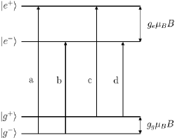
From Figure 2 we see that the ground state g values can be expressed as:
| (1) |
And the excited state g values can be expressed as:
| (2) |
In both of the above equations, is the applied magnetic field strength and is the Bohr Magneton.
III Results and Discussion
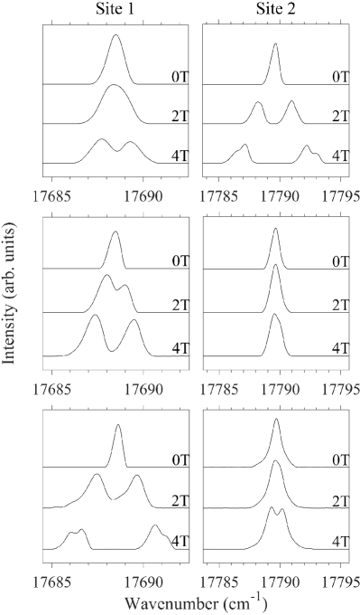
Initially Zeeman absorption spectroscopy was performed on Sm3+:Y2SiO5 which, owing to the geometry of our setup, limited the ability of determining the g values to only along the D1, D2 and b axes of Y2SiO5. Figure 3 shows the optical Zeeman absorption spectra for the 6H5/2ZG5/2A1 transitions with magnetic fields applied along the extinction axes of the Sm3+:Y2SiO5 sample. The small ground state splitting is unresolvable in some directions. The g values that could be measured using optical absorption were calculated using equations (1) and (2) and are summarized in Table 1. The g values were assigned as belonging to either the ground or excited state through comparison to other lines found in absorption, (not included here for brevity), as every transition shares a common ground state.
| Site 1 | Site 2 | ||||
|---|---|---|---|---|---|
| Direction | Ground | Excited | Ground | Excited | |
| D1 | – | 1.0 | 0.4 | 3.2 | |
| D2 | – | 1.2 | – | 0.3 | |
| b | 0.3 | 2.4 | – | 0.6 | |
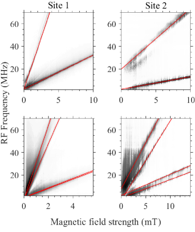
Zeeman spectroscopy proved to be insufficient to derive the full g tensor of any one state as the full g tensor has 6 independent components and therefore requires g values to be obtained along at least 6 different directions. Raman heterodyne spectroscopy was performed at low magnetic field strengths along 9 different directions in order to determine the g tensors for the ground 6H5/2Z1 and optically excited 4G5/2A1 states of both sites. All spectra were obtained at 3.5 K and the magnetic field was applied down the three extinction axes or at 45∘ between two of the axes resulting in 9 different directions.
Figure 4 shows representative Raman heterodyne spectra for the 6H5/2ZG5/2A1 transition for site 1 (left panels) and site 2 (right panels) in Sm3+:Y2SiO5 along the D2 direction (top panels) and the D2,b direction (bottom panels), obtained at 3.5 K. Note that the magnetic field strength varies between spectra and that the zero offsets are due to a stray magnetic field. The Zeeman transitions of interest are the linear lines visible in each spectrum. The top spectra has a magnetic field applied along the D2 axis and show two transitions, one representing the splitting of the ground state and the other representing the splitting of the excited state. The presence of four transitions in the D1,b and D2,b directions as represented in the bottom two panels in Figure 4 are due to the two magnetically inequivalent subsites of Y2SiO5. The additional structure seen in Figure 4 we attribute to interactions that arise from the relatively high concentration of our sample (0.5 molar %) in addition to unresolved hyperfine structure from both of the non-zero nuclear spin isotopes.
The g values of the 6H5/2Z1 ground and 4G5/2A1 excited states were determined and are summarized in Table 2. These g values agree with those found in Zeeman absorption spectroscopy as given in Table 1. Each state in the D1, b and D2, b directions have two related g values which arises from the two magnetically inequivalent subsites. In the case of Y2SiO5, the D1,+b and D1,-b directions in addition to the the D2,+b and the D2,-b directions are degenerate, therefore the average of the two g values were used in determining the g tensors. Preliminary crystal-field analyses performed on Sm3+:Y2SiO5 have shown that the g values for the ground state are significantly smaller than those of the excited state in most directions, and therefore distinguishing their g values is trivial [18]. The exception to this are the g values in the D2, b and D2,b directions for site 2 where both the ground and excited states have g values significantly less than one. These g values were classified as belonging to that of either the ground or excited state by constructing a g tensor for every remaining combination of g values and determining the g tensor that provided the closest agreement to the experimental data.
| Site 1 | Site 2 | ||||
|---|---|---|---|---|---|
| Direction | Ground | Excited | Ground | Excited | |
| D1 | 0.36 (0.04) | 1.07 (0.31) | 0.52 (0.05) | 3.29 (0.51) | |
| D2 | 0.21 (0.09) | 1.29 (0.21) | 0.078 (0.005) | 0.38 (0.11) | |
| b | 0.39 (0.02) | 2.46 (0.19) | 0.15 (0.01) | 0.77 (0.11) | |
| D1,+D2 | 0.31 (0.05) | 0.94 (0.14) | 0.34 (0.05) | 2.13 (0.16) | |
| D1,-D2 | 0.39 (0.18) | 1.43 (0.34) | 0.41 (0.05) | 2.61 (0.09) | |
| D1, b | 0.28, 0.50 (0.01, 0.15) | 1.77, 2.16 (0.08, 0.42) | 0.27, 0.44 (0.05, 0.02) | 2.40, 2.42 (0.24, 0.35) | |
| D2, b | 0.29, 0.29 (0.12, 0.12) | 1.68, 2.29 (0.23, 0.49) | 0.10, 0.146 (0.01, 0.005) | 0.50, 0.66 (0.08, 0.06) | |
Following the conventions of Weil et. al. we relate the g values, , with a magnetic field applied along an arbitrary direction to the g tensor, , through the following relationship [27]:
| (3) |
For a particular magnetic field direction, Equation (3) is transformed to:
| (4) |
and
| (5) |
Here and are the basis vectors of the Cartesian coordinate system and are the unit vectors in the directions. From Equations (4) and (5) the off-diagonal components of the g tensor can be expressed as:
| (6) |
Using Equations (4) and (6) the full g tensors can be determined. The g tensor is symmetric and therefore has 6 independent components that are required to be determined. Equations (7 – 10) show the g tensors of the 6H5/2Z1 ground ( for site 1 and for site 2) and 4G5/2A1 excited ( for site 1 and for site 2) states in Sm3+:Y2SiO5 that provides the closest agreement to the experimental data.
| (7) |
| (8) |
| (9) |
| (10) |
Figures 5 and 6 depict the angular dependence of the g values for the 6H5/2Z1 ground and 4G5/2A1 excited states of sites 1 and 2 respectively. The top panel depict a rotation in the D1-D2 () plane with corresponding to the D1 axis and corresponding to the D2 axis. The middle panel depict a rotation in the b-D1 () plane with corresponding to the b axis and corresponding to the D1 axis. The bottom panel depict a rotation in the b-D2 () plane with corresponding to the b axis and corresponding to the D2 axis. The experimental data is depicted as solid circles for the ground state and as hollow circles for the excited state.
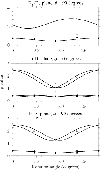
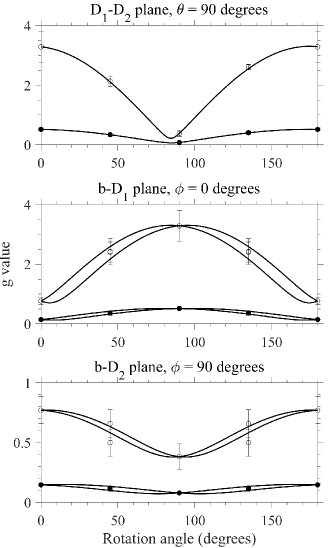
Table 3 depicts the principal axes and related direction cosines obtained by diagonalising the g tensors given in Equations (7) — (10). The principal axes are the eigenvectors of the g tensor while the principal g values are their corresponding eigenvalues. The principal axes are labelled , and with the maximum and minimum g value directions labelled as and respectively.
| Ground state | Excited state | |||||||||
|---|---|---|---|---|---|---|---|---|---|---|
| Principal g | l | m | n | Principal g | l | m | n | |||
| Site 1 | g | 0.447 | 0.635 | -0.066 | 0.770 | 2.490 | 0.087 | 0.143 | 0.986 | |
| g | 0.288 | -0.764 | 0.093 | 0.639 | 1.411 | 0.573 | -0.817 | 0.068 | ||
| g | 0.208 | 0.114 | 0.994 | -0.009 | 0.818 | 0.815 | 0.559 | -0.152 | ||
| Site 2 | g | 0.523 | -0.986 | 0.088 | 0.140 | 3.319 | -0.991 | 0.095 | -0.095 | |
| g | 0.128 | -0.144 | -0.045 | -0.989 | 0.730 | -0.068 | 0.259 | 0.964 | ||
| g | 0.063 | 0.081 | 0.995 | -0.057 | 0.113 | 0.116 | 0.961 | -0.251 | ||
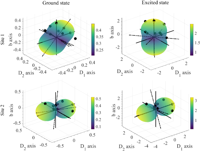
Figure 7 gives a visual representation of the g tensors. The g tensors derived in Equations (7) — (10) were used to derive the effective g values in terms of the extinction axes for both the 6H5/2Z1 ground state and the 4G5/2A1 excited state of Y2SiO5. The extinction and principal axes are also depicted as the solid and dash-dotted lines respectively.
IV Conclusion
We have studied the 6H5/2Z1 and 4G5/2A1 states for both crystallographic sites in Sm3+:Y2SiO5 through the use of Raman heterodyne spectroscopy. The g values determined along 9 different crystallographic directions were used to determine the full g tensors for these states. Sm3+:Y2SiO5 is an attractive alternative in the development of quantum information storage and communication devices relative to traditional systems such as Pr3+:Y2SiO5 and Eu3+:Y2SiO5. This is due to Sm3+ possessing a large hyperfine splitting, multiple non-zero nuclear spin isotopes, and a relative insensitivity to magnetic field fluctuations when compared to Er3+:Y2SiO5, which is a result of the very small ground state g values. This allows for the possibility of a multitude of ZEFOZ points to be experimentally determined and utilized for greater bandwidth quantum information storage and communication devices.
Acknowledgements.
NLJ would like to thank the Dodd-Walls Centre for Photonic and Quantum Technologies for the provision of a PhD studentship. The technical assistance of Mr J. Everts and Ms M. Cormack is gratefully acknowledged.References
- Zhong et al. [2017] T. Zhong, J. M. Kindem, J. G. Bartholomew, J. Rochman, I. Craiciu, E. Miyazono, M. Bettinelli, E. Cavalli, V. Verma, S. W. Nam, F. Marsili, M. D. Shaw, A. D. Beyer, and A. Faraon, Nanophotonic rare-earth quantum memory with optically controlled retrieval, Science 357, 1392 (2017).
- de Riedmatten et al. [2008] H. de Riedmatten, M. Afzelius, M. U. Staudt, C. Simon, and N. Gisin, A solid-state light-matter interface at the single-photon level, Nature 456, 773 (2008).
- Rančić et al. [2017] M. Rančić, M. P. Hedges, R. L. Ahlefeldt, and M. J. Sellars, Coherence time of over a second in a telecom-compatible quantum memory storage material, Nat. Phys. 14, 50–54 (2017).
- Longdell and Sellars [2004] J. J. Longdell and M. J. Sellars, Experimental demonstration of quantum-state tomography and qubit-qubit interactions for rare-earth-metal-ion-based solid-state qubits, Phys. Rev. A 69, 032307 (2004).
- Rippe et al. [2008] L. Rippe, B. Julsgaard, A. Walther, Y. Ying, and S. Kröll, Experimental quantum-state tomography of a solid-state qubit, Phys. Rev. A 77, 022307 (2008).
- Wesenberg and Mølmer [2003] J. Wesenberg and K. Mølmer, Robust quantum gates and a bus architecture for quantum computing with rare-earth-ion-doped crystals, Phys. Rev. A 68, 012320 (2003).
- Fraval et al. [2004] E. Fraval, M. Sellars, A. Morrison, and A. Ferris, interaction in :, J. Lumin. 107, 347 (2004).
- Heinze et al. [2013] G. Heinze, C. Hubrich, and T. Halfmann, Stopped light and image storage by electromagnetically induced transparency up to the regime of one minute, Phys. Rev. Lett. 111, 033601 (2013).
- Zhong et al. [2015] M. Zhong, M. P. Hedges, R. L. Ahlefeldt, J. G. Bartholomew, S. E. Beavan, S. M. Wittig, J. J. Longdell, and M. J. Sellars, Optically addressable nuclear spins in a solid with a six-hour coherence time, Nature 517, 177 (2015).
- Longdell et al. [2002a] J. J. Longdell, M. J. Sellars, and N. B. Manson, Hyperfine interaction in ground and excited states of praseodymium-doped yttrium orthosilicate, Phys. Rev. B 66, 035101 (2002a).
- Lovrić et al. [2012] M. Lovrić, P. Glasenapp, and D. Suter, Spin hamiltonian characterization and refinement for Pr3+:YAlO3 and Pr3+:Y2SiO5, Phys. Rev. B 85, 014429 (2012).
- Longdell et al. [2006] J. J. Longdell, A. L. Alexander, and M. J. Sellars, Characterization of the hyperfine interaction in europium-doped yttrium orthosilicate and europium chloride hexahydrate, Phys. Rev. B 74, 195101 (2006).
- Horvath et al. [2019] S. P. Horvath, J. V. Rakonjac, Y.-H. Chen, J. J. Longdell, P. Goldner, J.-P. R. Wells, and M. F. Reid, Extending phenomenological crystal-field methods to C1 point-group symmetry: Characterization of the optically excited hyperfine structure of 167Er3+:Y2SiO5, Phys. Rev. Lett. 123, 057401 (2019).
- Ortu et al. [2018] A. Ortu, A. Tiranov, S. Welinski, F. Fröwis, N. Gisin, A. Ferrier, P. Goldner, and M. Afzelius, Simultaneous coherence enhancement of optical and microwave transitions in solid-state electronic spins, Nat. Mater 17, 671 (2018).
- Rakonjac et al. [2020] J. V. Rakonjac, Y.-H. Chen, S. P. Horvath, and J. J. Longdell, Long spin coherence times in the ground state and in an optically excited state of : at zero magnetic field, Phys. Rev. B 101, 184430 (2020).
- Welinski et al. [2016] S. Welinski, A. Ferrier, M. Afzelius, and P. Goldner, High-resolution optical spectroscopy and magnetic properties of Yb3+ in Y2SiO5, Phys. Rev. B 94, 155116 (2016).
- Guillot-Noël et al. [2006] O. Guillot-Noël, P. Goldner, Y. L. Du, E. Baldit, P. Monnier, and K. Bencheikh, Hyperfine interaction of ions in : An electron paramagnetic resonance spectroscopy study, Phys. Rev. B 74, 214409 (2006).
- Jobbitt et al. [2019] N. L. Jobbitt, S. J. Patchett, Y. Alizadeh, M. F. Reid, J.-P. R. Wells, S. P. Horvath, J. J. Longdell, A. Ferrier, and P. Goldner, Transferability of crystal-field parameters for rare-earth ions in tested by Zeeman spectroscopy, Phys. Sol. State 61, 780 (2019).
- Jobbitt et al. [2020] N. L. Jobbitt, J.-P. R. Wells, and M. F. Reid, Energy transfer between ions in crystals, J. Lumin. 224, 117302 (2020).
- Mlynek et al. [1983] J. Mlynek, N. C. Wong, R. G. DeVoe, E. S. Kintzer, and R. G. Brewer, Raman heterodyne detection of nuclear magnetic resonance, Phys. Rev. Lett. 50, 993 (1983).
- Wong et al. [1983] N. Wong, E. Kintzer, J. Mlynek, R. DeVoe, and R. Brewer, Raman heterodyne detection of nuclear magnetic resonance, Physical Review B 28, 4993 (1983).
- Longdell et al. [2002b] J. J. Longdell, M. J. Sellars, and N. B. Manson, Hyperfine interaction in ground and excited states of praseodymium-doped yttrium orthosilicate, Phys. Rev. B 66, 035101 (2002b).
- Fernandez-Gonzalvo et al. [2015] X. Fernandez-Gonzalvo, Y.-H. Chen, C. Yin, S. Rogge, and J. J. Longdell, Coherent frequency up-conversion of microwaves to the optical telecommunications band in an : crystal, Phys. Rev. A 92, 062313 (2015).
- Maksimov et al. [1970] B. Maksimov, V. Ilyukhin, Y. A. Kharitonov, and N. Belov, Crystal structure of yttrium oxyorthosilicate , Kristallografiya 15 (1970).
- Li et al. [1992] C. Li, C. Wyon, and R. Moncorge, Spectroscopic properties and fluorescence dynamics of :, IEEE J. Quantum Electron. 28, 1209 (1992).
- Sun et al. [2008] Y. Sun, T. Böttger, C. Thiel, and R. Cone, Magnetic g tensors for the and states of :, Phys. Rev. B 77 (2008).
- Weil and Bolton [2007] J. A. Weil and J. R. Bolton, Electron paramagnetic resonance: Elementary theory and practical applications (Wiley, 2007) Chap. 4, pp. 85–111.