Room temperature cavity electromechanics in the sideband-resolved regime
Abstract
We demonstrate a sideband-resolved cavity electromechanical system operating at room temperature. It consists of a nanomechanical resonator, a strongly pre-stressed silicon nitride string, dielectrically coupled to a three-dimensional microwave cavity made of copper. The electromechanical coupling is characterized by two measurements, the cavity-induced eigenfrequency shift of the mechanical resonator and the optomechanically induced transparency. While the former is dominated by dielectric effects, the latter reveals a clear signature of the dynamical backaction of the cavity field on the resonator. This unlocks the field of cavity electromechanics for room temperature applications.
I Introduction
In recent years, cavity (or circuit) electromechanics has been established as a powerful implementation of cavity optomechanics. Aspelmeyer, Kippenberg, and Marquardt (2014) Rather than relying on a light field circulating inside an optical cavity, an electromagnetic circuit is employed to realize a cavity mode in the microwave regime which parametrically couples to a mechanical resonator. Regal, Teufel, and Lehnert (2008); Teufel et al. (2008, 2011a); Pernpeintner et al. (2014) This seemingly simple modification has enabled a series of breakthroughs, including quantum ground state cooling, Teufel et al. (2011b) entanglement generation, Palomaki et al. (2013a); Barzanjeh et al. (2019) long-lived quantum storage, Palomaki et al. (2013b); Zhou et al. (2013); Pechal, Arrangoiz-Arriola, and Safavi-Naeini (2018) microwave-to-optical conversion, Andrews et al. (2014); Forsch et al. (2019) non-reciprocal signal transduction, Barzanjeh et al. (2017) and ultrastrong coupling Peterson et al. , just to name a few. Following recent developments in the field of superconducing qubits Paik et al. (2011); Reagor et al. (2013) where three-dimensional microwave cavities have replaced coplanar waveguide architectures for their large mode volumes and remarkably high quality factors, three-dimensional superconducting microwave cavities have been adapted for cavity electromechanics by capacitive coupling to a mechanical resonator. Yuan et al. (2015); Noguchi et al. (2016); Carvalho et al. (2019) However, to date, the field of cavity electromechanics is limited to millikelvin temperatures, since it relies on superconducting circuits. Room temperature cavity electromechanics is impeded by the non-zero resistance of normal conducting circuits which gives rise to dissipation. Non-superconducting microwave cavities such as copper microstrip resonators have been successfully employed for cavity-assisted displacement sensing of nanomechanical resonators at room temperature. Faust et al. (2012); Rieger et al. (2012) Their use for cavity electromechanics Faust et al. (2012) is limited by a cavity quality factor of about due to dielectric and conductor losses, which not only constrains the displacement sensitivity but also keeps the system deeply in the unresolved sideband, so-called bad cavity regime where the linewidth of the cavity exceeds the frequency of the mechanical mode .
Here we present a room temperature cavity electromechanical system capable of sideband-resolved operation (). Inspired by the developments in the field of superconducing qubits Paik et al. (2011); Reagor et al. (2013) and cavity electromechanics Yuan et al. (2015); Noguchi et al. (2016); Carvalho et al. (2019) we employ a three-dimensional, cylindrically shaped cavity rather than a microstrip to dielectrically probe the displacement of a strongly pre-stressed silicon nitride nanostring resonator.
II Results and discussion
Figure 1(a) depicts a photograph of the cylindrical cavity. It consists of two parts which have been machined from bulk copper (Cu > 99.90 %) and which can be closed using screws. The cavity has a radius of mm and a height of mm, it supports both transverse electric (TE) and transverse magnetic (TM) modes. Pozar (2011) As the modes reside in the hollow cylinder, they are only weakly affected by dielectric and conductor losses, enabling high quality factor even at room temperature. Reagor et al. (2013) The coupling to the cavity is realized by injecting the microwave signal from a coaxial line through a loop coupler via a mm sized hole in the cavity top. In all our measurements, we use a circulator to physically separate the input and output signals of the single port reflection cavity. Figure 1(b) (left) displays the reflection coefficient of the mode which is found at GHz with a linewidth of MHz for the empty cavity, in good agreement with finite element simulations. This corresponds to a cavity quality factor of , exceeding the state of the art in microwave-cavity-assisted nanomechanical displacement sensing at room temperature by more than an order of magnitude. Faust et al. (2012) The nanomechanical resonator under investigation is a strongly pre-stressed nanostring fabricated from LPCVD silicon nitride on a fused silica wafer, which is flanked by two gold electrodes for dielectric transduction. Faust et al. (2012); Rieger et al. (2012) The reflection coefficient of the cavity including the resonator chip is shown in Figure 1(b) (right). Upon insertion of the resonator, the eigenfrequency of the mode shifts to GHz. The linewidth increases by a factor of to MHz.
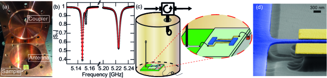
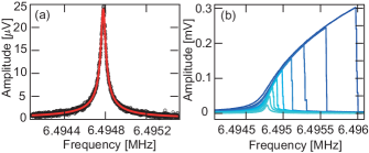
In addition, the fit of the amplitude and phase of the cavity’s reflection coefficient reveals an external dissipation rate of MHz. This gives rise to a coupling efficiency , indicating that the cavity is undercoupled. Figure 1(c) shows the physical realization of the cavity electromechanical system. The sample holder with the resonator chip is placed inside the cavity. One of the electrodes is connected to an antenna to inductively couple to the of the cavity. It consists of a looped silver wire on top of a coaxial cable which places the loop into the electromagnetic field near the center of the hollow cylinder. The other electrode is bonded across a single layer capacitor acting as capacitive ground Rieger et al. (2012) and connected to an RF signal generator through a mm wide hole in the cavity wall for dielectric actuation of the resonator. Chen et al. (2011); de Graaf et al. (2014); Hao, Rouxinol, and LaHaye (2014); Kong et al. (2015); Cohen et al. (2017); Stammeier, Garcia, and Wallraff (2018) The nanostring under investigation is nm wide, nm thick and m long, similar to the one depicted in Fig. 1(d). While the cavity characterization is done under ambient conditions, the experiments discussed in the following involve the vibrational excitation of the nanostring and air damping needs to be excluded. Hence, the entire cavity electromechanical system consisting of the string resonator as well as the microwave cavity is placed inside a vacuum chamber below mbar. As indicated above, all measurements are performed at room temperature. The nanomechanical resonator is characterized by dielectrically driving its fundamental out-of-plane mode with a vector network analyzer (VNA). The response of the nanomechanical resonator is characterized using heterodyne cavity-assisted displacement detection Faust et al. (2012) using the three-dimensional microwave cavity. The microwave cavity is driven on resonance , such that the periodic modulation of the capacitance induced by the dielectric nanostring vibrating between the two electrodes induces sidebands at on the cavity response. The reflected signal of the cavity is demodulated by an in-phase quadrature (IQ) mixer, filtered and amplified as previously described. Faust et al. (2012) The resulting signal is fed back into the VNA. The response of the fundamental out-of-plane mode of the resonator is displayed in Fig. 2. Figure 2(a) shows the Lorentzian resonance curve observed in the linear response regime for a drive power dBm. Fitting allows to extract the resonance frequency MHz, as well as a linewidth Hz which gives rise to a quality factor of . Given the cavity linewidth MHz the condition for sideband resolution, , is fulfilled for the mode. The response of the resonator for increasing drive power between dBm to dBm is depicted in Fig. 2(b). Clearly, the transition from the linear, Lorentzian response to an asymmetric response curve, which is well described by the cubic nonlinearity of the Duffing model with a stiffening , is observed. Nayfeh and Mook (1995) This demonstrates that the cavity-assisted displacement detection is not impeded even under strong driving of the nanomechanical resonator inside the 3D cavity.
Following the characterization of the microwave cavity and the resonator, we discuss the electromechanical coupling between the two systems. First, we explore how the cavity detuning affects the mechanical eigenfrequency of the resonator. The radiation pressure of the power circulating in the microwave cavity acts back on the mechanical resonator, causing a mechanical eigenfrequency shift which depends on the microwave drive power and detuning . This so-called optical spring effect leads to a detuning-dependent softening or hardening of the resonator. In case of a high-Q mechanical oscillator with small linewidth, where , the frequency shift of the mechanical oscillator can be defined as Aspelmeyer, Kippenberg, and Marquardt (2014)
| (1) |
The electromechanical coupling strength depends on the single photon coupling rate and the number of photons circulating in the cavity . Note that this quantity strongly depends on the detuning of the cavity. Hence, for a given power the intra-cavity photon number
of the single-sided cavity can be significantly reduced for a finite cavity detuning.
As the static mechanical displacement of the resonator arising from the radiation pressure force Aspelmeyer, Kippenberg, and Marquardt (2014) is negligibly small, the detuning rather than the effective detuning is employed in eq. (1)
In addition to the optomechanical backacktion we also expect a quasi-static dielectric force acting on the mechanical resonator. This force results from the root-mean-square (RMS) electrical field which builds up inside the microwave cavity and contributes to the dielectric frequency tuning of the nanostring Rieger et al. (2012). As the RMS cavity field exhibits the same detuning-dependence as the intracavity photon number , this translates into a change in eigenfrequency of the mechanical oscillator as the cavity is detuned from its resonance
| (2) |
The calibration factor converts the change of the effective RMS voltage inside the cavity into a frequency change, and is the impedance of the circuit allowing to express the RMS voltage in terms of the power circulating in the cavity. In total, the detuning dependence of the mechanical resonance is
| (3) |
where is the unperturbed mechanical eigenfrequency.
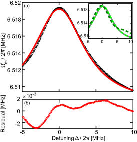
In Fig. 3(a) the nanomechanical resonator’s eigenfrequency is plotted as a function of the detuning (black circles) for a cavity drive power of dBm. The data is well described by eq. (3), which is apparent from a fit to the data (red line). However, the fit yields an overwhelming contribution of the dielectric frequency shift and only negligible optomechanical backaction such that the optomechanical coupling strength can not be determined. The inset of Fig. 3(a) shows the theoretical prediction of the eigenfrequency according to eq. (3) using the parameters of the experiment for three different values of : The grey solid line illustrates the eigenfrequency shift for zero optomechanical coupling Hz. As eq. (2) does not depend on the sign of , it is mirror symmetric with respect to the -axis. The light green dashed line corresponds to Hz, which is the value of the single photon coupling rate estimated from the data in Fig. 4. The line completely coincides with the grey line, confirming that the optomechanical coupling has no measurable effect on the eigenfrequency shift. Minute deviations start becoming apparent from mHz which we thus estimate as an upper bound of the single photon coupling rate. The dark green dashed line for mHz already shows a sizable deviation of the eigenfrequency shift resulting from optomechanical coupling. Our observation of a negligible optomechanical eigenfrequency shift is supported by the nearly mirror-symmetric shape of the measured eigenfrequency shift of the resonator around zero detuning in Fig. 3(a). The slight deviation shifting the maximum to a small positive detuning is likely caused by a slight drift of the mechanical eigenfrequency from slow polarization effects within the nanostring during the cavity frequency sweep, the opposite effect would be expected from radiation pressure effects. Figure Fig. 3(b) shows the residual of the data vs. the fit. We attribute the observed pattern to the same slow polarization effects. The small value of is consistent with our observation that the mechanical linewidth does not yield any measurable detuning dependence in our experiment (not shown).
In order to obtain a better estimation of the electromechanical coupling strength, we apply a second technique to characterize the parametric coupling between the nanostring and the three-dimensional cavity. It is based on the optomechanically induced transparency (OMIT), Agarwal and Huang (2010); Weis et al. (2010); Teufel et al. (2011a) which arises from the coherent interaction of two microwave tones with the mechanical resonator in the resolved sideband regime. Singh et al. (2014) In an OMIT experiment, the cavity is strongly pumped by a drive tone which is red detuned from the cavity resonance by the frequency of the mechanical resonator. The cavity response is measured by a second, weak probe tone that is scanned across the cavity resonance. The beating between the two microwave tones induces a radiation pressure force coherently driving the mechanical resonator. In turn, the resonator imprints sidebands on the drive which interfere constructively with the probe. This opens a transparency window in the cavity transmission (or, as in our case, the cavity reflection which strictly speaking leads to optomechanically induced reflection (OMIR) Singh et al. (2014)). According to the standard theory of OMIT, the height of the transparency peak allows to directly extract the cooperativity , rendering OMIT an important tool in cavity opto- and electromechanics.
In Fig. 4(a) we plot the response of the microwave cavity as a function of the probe frequency for a drive applied at optimal detuning . The drive and probe power are dBm and dBm, respectively. A transparency feature at is clearly apparent in the center of the cavity resonance. Note that the peak is not symmetric. Its asymmetry reflects the nonlinear response of the mechanical resonator to the radiation pressure drive exerted by the two microwave tones. Zhou et al. (2013); Shevchuk et al. (2015); Singh et al. (2016) In agreement with the standard model for OMIR for the case of an undercoupled cavity driven on the red sideband, the shape of the nonlinear transparency peak directly follows the response of the Duffing resonator. Zhou et al. (2013); Shevchuk et al. (2015) This is also reflected in the hysteretic behavior of the OMIR feature displayed in Fig. 4(b) for a forward (black) as well as a reverse (red) sweep of the cavity probe at a somewhat lower probe power to maximize the magnitude of the OMIR feature. Figure 4(c) illustrates the dependence of OMIR peak on the probe power. The curves (from left to right) correspond to an increasing probe power from dBm to dBm. As expected, the width of the nonlinear feature broadens with increasing probe power while its amplitude slightly decreases.Shevchuk et al. (2015) Finally, the effect of a detuning of the cavity drive from the red sideband condition, , is explored in Fig. 4(d) for a constant probe power of dBm. For a drive tone red- or blue-shifted from the red-sideband condition ( kHz, red and blue trace, respectively), the OMIR peak moves away from the minimum of the cavity response at . Shevchuk et al. (2015) The data for the drive matched to the red sideband is also included ( Hz, black trace). For clarity, the red and blue trace are vertically offset from the black trace.
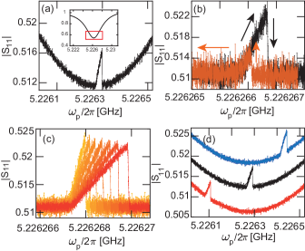
According to the standard theory of OMIR, the height of the transparency peak allows to quantify the cooperativity. For the case of an undercoupled cavity driven on the red sideband, . Neither the nonlinear regime nor a poor sideband resolution greatly affect the magnitude of the OMIR feature. Shevchuk et al. (2015); Bodiya et al. (2019) Using the yellow trace in Fig. 4(c), extract an approximate value of . This translates into an optomechanical coupling strength of kHz, and, given a cavity photon number of at a drive power of dBm on the red sideband, to a single photon coupling rate of Hz.
It is noteworthy to mention that such a feeble single photon coupling can produce observable features in the OMIT experiment at all. This is enabled by the large number of photons supported by the three-dimensional microwave cavity, which exceeds photon numbers achieved in planar microwave resonators at low temperatures Singh et al. (2014); Teufel et al. (2011a) by at least four orders of magnitude and is at present only limited by the maximum output power of our microwave generator. The observed weak single photon coupling strength is attributed to our cavity design, as the loop antenna could not be precisely positioned in the cavity in our experiment and presumably only weakly couples to the cavity mode. At the same time, the electromechanical coupling of the nanostring to the electrodes is limited by a relatively large electrode-electrode separation of approx. nm for the sample under investigation. For future work on the room temperature cavity electromechanics platform, an improved control of the antenna position as well as a smaller electrode gap will enable to significantly increase .
III Conclusion
In conclusion, we have demonstrated a cavity electromechanical system operating in the sideband resolved regime at room temperature. This was accomplished by introducing a three-dimensional, non-superconducting microwave cavity made of copper which replaces the previously employed copper microstrip cavity, the quality factor of which is outperformed by more than an order of magnitude. In our experiment a non-metallized silicon nitride nanostring resonator was dielectrically coupled to the mode of the cavity which offers almost perfect sideband resolution . Electromechanical coupling was observed and characterized in one- and two-microwave tone experiments. While the mechanical eigenfrequency shift is dominated by dielectric frequency tuning, the optomechanically induced transparency (in reflection geometry) establishes a clear proof of dynamical backaction. Despite the minute single photon coupling rate of our first implementation of the room temperature cavity electromechanical plattform in the sub-mHz regime, a measureable coupling is enabled by the large number of photons circulating in the three-dimensional microwave cavity. As a result of the required strong red-detuned cavity drive, the response of the mechanical resonator is nonlinear in our proof-of-principle experiment.
Our results translate the thriving field of cavity electromechanics from the millikelvin realm to room temperature. For future exploitation, the electromechanical vacuum coupling rate will need to be increased. This can be accomplished by an improved positioning of the loop antenna providing the coupling between the cavity mode and the control electrodes. Furthermore, the coupling can be enhanced by increasing the dielectric transduction efficiency, i.e. by reducing the lateral gap between the electrodes. Following these technical improvements, we expect to reveal the electromechanical cooling or pumping of the mechanical mode. Finally, the quality factor or the mode exceeds that of the mode by another order of magnitude, which offers the prospect of entering the deep-sideband-resolved regime of cavity electromechanics at room temperature.
Acknowledgements.
Financial support from the Deutsche Forschungsgemeinschaft (DFG, German Research Foundation) via Project-ID 425217212 (Collaborative Research Center SFB 1432)); the European Unions Horizon 2020 programme for Research and Innovation under grant agreement No. 732894 (FET Proactive HOT), as well as the German Federal Ministry of Education and Research through contract no. 13N14777 funded within the European QuantERA cofund project QuaSeRT is gratefully acknowledged.Data Availability
The data that support the findings of this study are available from the corresponding author upon reasonable request.
References
References
- Aspelmeyer, Kippenberg, and Marquardt (2014) M. Aspelmeyer, T. J. Kippenberg, and F. Marquardt, “Cavity optomechanics,” Reviews of Modern Physics 86, 1391–1452 (2014).
- Regal, Teufel, and Lehnert (2008) C. A. Regal, J. D. Teufel, and K. W. Lehnert, “Measuring nanomechanical motion with a microwave cavity interferometer,” Nature Physics 4, 555 – 560 (2008).
- Teufel et al. (2008) J. D. Teufel, J. W. Harlow, C. A. Regal, and K. W. Lehnert, “Dynamical backaction of microwave fields on a nanomechanical oscillator,” Physical Review Letters 101, 197203 (2008).
- Teufel et al. (2011a) J. D. Teufel, D. Li, M. S. Allman, K. Cicak, A. J. Sirois, J. D. Whittaker, and R. W. Simmonds, “Circuit cavity electromechanics in the strong-coupling regime,” Nature 471, 204–208 (2011a).
- Pernpeintner et al. (2014) M. Pernpeintner, T. Faust, F. Hocke, J. P. Kotthaus, E. M. Weig, H. Huebl, and R. Gross, “Circuit electromechanics with a non-metallized nanobeam,” Applied Physics Letters 105, 123106 (2014).
- Teufel et al. (2011b) J. D. Teufel, T. Donner, D. Li, J. W. Harlow, M. S. Allman, K. Cicak, A. J. Sirois, J. D. Whittaker, K. W. Lehnert, and R. W. Simmonds, “Sideband cooling of micromechanical motion to the quantum ground state,” Nature 475, 359–363 (2011b).
- Palomaki et al. (2013a) Palomaki, T. A., Teufel, J. D., Simmonds, R. W., Lehnert, and K. W., “Entangling mechanical motion with microwave fields,” Science 342, 710–713 (2013a), http://www.sciencemag.org/content/342/6159/710.full.pdf .
- Barzanjeh et al. (2019) S. Barzanjeh, E. S. Redchenko, M. Peruzzo, M. Wulf, D. P. Lewis, G. Arnold, and J. M. Fink, “Stationary entangled radiation from micromechanical motion,” Nature 570, 480–483 (2019).
- Palomaki et al. (2013b) T. A. Palomaki, J. W. Harlow, J. D. Teufel, R. W. Simmonds, and K. W. Lehnert, “Coherent state transfer between itinerant microwave fields and a mechanical oscillator,” Nature 495, 210–214 (2013b).
- Zhou et al. (2013) X. Zhou, F. Hocke, A. Schliesser, A. Marx, H. Huebl, R. Gross, and T. J. Kippenberg, “Slowing, advancing and switching of microwave signals using circuit nanoelectromechanics,” Nature Physics 9, 179–184 (2013).
- Pechal, Arrangoiz-Arriola, and Safavi-Naeini (2018) M. Pechal, P. Arrangoiz-Arriola, and A. H. Safavi-Naeini, “Superconducting circuit quantum computing with nanomechanical resonators as storage,” Quantum Science and Technology 4, 015006 (2018).
- Andrews et al. (2014) R. W. Andrews, R. W. Peterson, T. P. Purdy, K. Cicak, R. W. Simmonds, C. A. Regal, and K. W. Lehnert, “Bidirectional and efficient conversion between microwave and optical light,” Nature Physics 10, 321–326 (2014).
- Forsch et al. (2019) M. Forsch, R. Stockill, A. Wallucks, I. Marinković, C. Gärtner, R. A. Norte, F. van Otten, A. Fiore, K. Srinivasan, and S. Gröblacher, “Microwave-to-optics conversion using a mechanical oscillator in its quantum ground state,” Nature Physics (2019), 10.1038/s41567-019-0673-7.
- Barzanjeh et al. (2017) S. Barzanjeh, M. Wulf, M. Peruzzo, M. Kalaee, P. B. Dieterle, O. Painter, and J. M. Fink, “Mechanical on-chip microwave circulator,” Nature Communications 8, 953 (2017).
- (15) G. A. Peterson, S. Kotler, F. Lecocq, K. Cicak, X. Y. Jin, R. W. Simmonds, J. Aumentado, and J. D. Teufel, “Ultrastrong parametric coupling between a superconducting cavity and a mechanical resonator,” http://arxiv.org/abs/1906.11353v1 .
- Paik et al. (2011) H. Paik, D. I. Schuster, L. S. Bishop, G. Kirchmair, G. Catelani, A. P. Sears, B. R. Johnson, M. J. Reagor, L. Frunzio, L. I. Glazman, S. M. Girvin, M. H. Devoret, and R. J. Schoelkopf, “Observation of high coherence in josephson junction qubits measured in a three-dimensional circuit QED architecture,” Physical Review Letters 107 (2011), 10.1103/physrevlett.107.240501.
- Reagor et al. (2013) M. Reagor, H. Paik, G. Catelani, L. Sun, C. Axline, E. Holland, I. M. Pop, N. A. Masluk, T. Brecht, L. Frunzio, M. H. Devoret, L. Glazman, and R. J. Schoelkopf, “Reaching 10 ms single photon lifetimes for superconducting aluminum cavities,” Applied Physics Letters 102, 192604 (2013).
- Yuan et al. (2015) M. Yuan, V. Singh, Y. M. Blanter, and G. A. Steele, “Large cooperativity and microkelvin cooling with a three-dimensional optomechanical cavity,” Nature Communications 6 (2015), 10.1038/ncomms9491.
- Noguchi et al. (2016) A. Noguchi, R. Yamazaki, M. Ataka, H. Fujita, Y. Tabuchi, T. Ishikawa, K. Usami, and Y. Nakamura, “Ground state cooling of a quantum electromechanical system with a silicon nitride membrane in a 3d loop-gap cavity,” New Journal of Physics 18, 103036 (2016).
- Carvalho et al. (2019) N. C. Carvalho, J. Bourhill, M. Goryachev, S. Galliou, and M. E. Tobar, “Piezo-optomechanical coupling of a 3d microwave resonator to a bulk acoustic wave crystalline resonator,” Applied Physics Letters 115, 211102 (2019).
- Faust et al. (2012) T. Faust, P. Krenn, S. Manus, J. Kotthaus, and E. Weig, “Microwave cavity-enhanced transduction for plug and play nanomechanics at room temperature,” Nature Communications 3 (2012), 10.1038/ncomms1723.
- Rieger et al. (2012) J. Rieger, T. Faust, M. J. Seitner, J. P. Kotthaus, and E. M. Weig, “Frequency and q factor control of nanomechanical resonators,” Applied Physics Letters 101, 103110 (2012).
- Pozar (2011) D. M. Pozar, Microwave Engineering (John Wiley and Sons Ltd, 2011).
- Chen et al. (2011) F. Chen, A. J. Sirois, R. W. Simmonds, and A. J. Rimberg, “Introduction of a dc bias into a high-q superconducting microwave cavity,” Appl. Phys. Lett. 98, 132509 (2011).
- de Graaf et al. (2014) S. E. de Graaf, D. Davidovikj, A. Adamyan, S. E. Kubatkin, and A. V. Danilov, “Galvanically split superconducting microwave resonators for introducing internal voltage bias,” Applied Physics Letters 104, 052601 (2014).
- Hao, Rouxinol, and LaHaye (2014) Y. Hao, F. Rouxinol, and M. D. LaHaye, “Development of a broadband reflective t-filter for voltage biasing high-q superconducting microwave cavities,” Applied Physics Letters 105, 222603 (2014), http://dx.doi.org/10.1063/1.4903777 .
- Kong et al. (2015) W.-C. Kong, G.-W. Deng, S.-X. Li, H.-O. Li, G. Cao, M. Xiao, and G.-P. Guo, “Introduction of DC line structures into a superconducting microwave 3d cavity,” Review of Scientific Instruments 86, 023108 (2015).
- Cohen et al. (2017) M. A. Cohen, M. Yuan, B. W. A. de Jong, E. Beukers, S. J. Bosman, and G. A. Steele, “A split-cavity design for the incorporation of a dc bias in a 3d microwave cavity,” Applied Physics Letters 110, 172601 (2017), http://dx.doi.org/10.1063/1.4981884 .
- Stammeier, Garcia, and Wallraff (2018) M. Stammeier, S. Garcia, and A. Wallraff, “Applying electric and magnetic field bias in a 3d superconducting waveguide cavity with high quality factor,” Quantum Science and Technology 3, 045007 (2018).
- Nayfeh and Mook (1995) A. H. Nayfeh and D. T. Mook, Nonlinear Oscillations (Wiley, 1995).
- Agarwal and Huang (2010) G. S. Agarwal and S. Huang, “Electromagnetically induced transparency in mechanical effects of light,” Physical Review A 81 (2010), 10.1103/physreva.81.041803.
- Weis et al. (2010) S. Weis, R. Rivière, S. Deléglise, E. Gavartin, O. Arcizet, A. Schliesser, and T. J. Kippenberg, “Optomechanically induced transparency,” Science 330, 1520–1523 (2010).
- Singh et al. (2014) V. Singh, S. J. Bosman, B. H. Schneider, Y. M. Blanter, A. Castellanos-Gomez, and G. A. Steele, “Optomechanical coupling between a multilayer graphene mechanical resonator and a superconducting microwave cavity,” Nature Nanotechnology 9, 820–824 (2014).
- Shevchuk et al. (2015) O. Shevchuk, V. Singh, G. A. Steele, and Y. M. Blanter, “Optomechanical response of a nonlinear mechanical resonator,” Physical Review B 92 (2015), 10.1103/physrevb.92.195415.
- Singh et al. (2016) V. Singh, O. Shevchuk, Y. M. Blanter, and G. A. Steele, “Negative nonlinear damping of a multilayer graphene mechanical resonator,” Physical Review B 93 (2016), 10.1103/physrevb.93.245407.
- Bodiya et al. (2019) T. Bodiya, V. Sudhir, C. Wipf, N. Smith, A. Buikema, A. Kontos, H. Yu, and N. Mavalvala, “Sub-hertz optomechanically induced transparency with a kilogram-scale mechanical oscillator,” Physical Review A 100 (2019), 10.1103/physreva.100.013853.