All-optical beam steering using the polariton lighthouse effect
Abstract
We demonstrate theoretically and experimentally that a specifically designed microcavity driven in the optical parametric oscillation regime exhibits lighthouse-like emission, i.e., an emission focused around a single direction. Remarkably, the emission direction of this micro-lighthouse is continuously controlled by the linear polarization of the incident laser, and angular beam steering over is demonstrated. Theoretically, this unprecedented effect arises from the interplay between the nonlinear optical response of microcavity exciton-polaritons, the difference in the subcavities forming the microcavity, and the rotational invariance of the device.
keywords:
Nonlinear Optics, All-Optical Signal Processing, Semiconductor Microcavity, PolaritonsUoA]Department of Physics, University of Arizona, Tucson, AZ 85721, USA LPENS]Laboratoire de Physique de l’Ecole Normale Supérieure, ENS, Université PSL, CNRS, Sorbonne Université, Université Paris-Diderot, Sorbonne Paris Cité, 24 rue Lhomond 75005 Paris, France LPENS]Laboratoire de Physique de l’Ecole Normale Supérieure, ENS, Université PSL, CNRS, Sorbonne Université, Université Paris-Diderot, Sorbonne Paris Cité, 24 rue Lhomond 75005 Paris, France Paderborn]Physics Department and Center for Optoelectronics and Photonics Paderborn (CeOPP), Universität Paderborn, Warburger Strasse 100, 33098 Paderborn, Germany Paderborn]Wyant College of Optical Sciences, University of Arizona, Tucson, AZ 85721, USA C2N]Centre de Nanosciences et de Nanotechnologies (C2N), CNRS, Université Paris Sud, Université Paris-Saclay, 91120 Palaiseau, France C2N]Centre de Nanosciences et de Nanotechnologies (C2N), CNRS, Université Paris Sud, Université Paris-Saclay, 91120 Palaiseau, France LPENS]Laboratoire de Physique de l’Ecole Normale Supérieure, ENS, Université PSL, CNRS, Sorbonne Université, Université Paris-Diderot, Sorbonne Paris Cité, 24 rue Lhomond 75005 Paris, France LPENS]Laboratoire de Physique de l’Ecole Normale Supérieure, ENS, Université PSL, CNRS, Sorbonne Université, Université Paris-Diderot, Sorbonne Paris Cité, 24 rue Lhomond 75005 Paris, France Paderborn]Physics Department and Center for Optoelectronics and Photonics Paderborn (CeOPP), Universität Paderborn, Warburger Strasse 100, 33098 Paderborn, Germany \alsoaffiliation[Paderborn]Wyant College of Optical Sciences, University of Arizona, Tucson, AZ 85721, USA UoA]Department of Physics, University of Arizona, Tucson, AZ 85721, USA \alsoaffiliation[Paderborn]Wyant College of Optical Sciences, University of Arizona, Tucson, AZ 85721, USA LPENS]Laboratoire de Physique de l’Ecole Normale Supérieure, ENS, Université PSL, CNRS, Sorbonne Université, Université Paris-Diderot, Sorbonne Paris Cité, 24 rue Lhomond 75005 Paris, France
1 Introduction
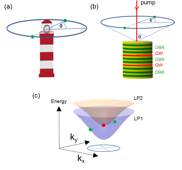
Lighthouses have been used for millennia to inform ships on their relative position on the sea. The lighthouse design possesses two advantages (Fig. 1a): Its highly directive radiation pattern allows limiting the required power to reach remote locations, and the dynamic control of the emission allows converting spatial information into time information, and vice versa. Such design is used in our everyday life in bar code readers, phased array radars or beamformer sonars.
Non-mechanical lighthouse designs are attractive because they allow reducing mechanical fatigue limitations, and increasing the lifetime, simplicity and speed of devices. There are two strategies to reach such goal: The first one relies on using the interference of a controllable array of antennas or light modulators. This method is inspired from the phased array radar technology 1 and usually requires complex photonic circuits in the visible wavelengths 2, 3, 4, 5, controlled electronically by phase shifters.
Another approach relies on using the nonlinear light-matter response to steer light, opening the road to all-optical operation. Steering can be achieved by using the light field intensity - usually of an auxiliary pump field - to modify the field propagation within the device. Beam steering has been achieved in this way to steer solitons 6, 7, intense fields in biased photorefractive crystals 8, femtosecond pulses on metallic mirrors 9, or to control the emission of spatial multimodal lasers by using the nonlinear gain response 10, 11.
The nonlinear approach has the advantage of much simpler and robust designs, it is also usually much faster. But since direction is not controlled independently of intensity, it is hard to imagine practical applications, e.g., in information technology, ranging or microscopy. In this letter we show that, rather surprisingly, the linear polarization is sufficient to achieve continuous control of the beam emission. We demonstrate the lighthouse-like emission of a planar multiple microcavity device (Fig. 1). This simple device is composed of two coupled microcavities containing multiple quantum wells 12. The strong coupling between cavity photons and quantum well excitons is reached and the collective excitations of the device are microcavity exciton-polaritons 13, 14, 15, which are part-light, part-matter quasiparticles and therefore exhibit strong nonlinear interactions. 16, 17, 18, 19, 20, 21 The dispersion of the two lower polariton branches (LP) is shown in figure 1c: When we resonantly pump the LP2 at normal incidence, a triply degenerate parametric scattering process occurs towards LP1, and light is emitted at a finite emission angle .
In principle, due to the rotational invariance of the polaritonic dispersion, parametric scattering can occur in any direction, but we predict and observe that in the nonlinear system the emission direction is controlled by the linear pump polarization in the optical parametric oscillation (OPO) regime allowing beam steering over an interval of the azimuth angle of .
2 Theory
To describe the scattering of LP2 polaritons at zero in-plane wave vector onto the LP1 elastic circle, we utilize the nonlinear coupled cavity and exciton field theory discussed in Ref. 22.
The core ingredients to this theory are interband polarization functions, obtained from a fermionic quantum-field theory and specialized to excitonic polarizations. The Coulomb interaction between charge carriers gives rise to spin-dependent exciton-exciton interactions and thus to two-exciton correlations, as for example obtained in the dynamics-controlled truncation formalism 23, 24. The nonlinear optical response of the two subcavities follows from a numerical solution of a coupled mode theory including the excitonic interband polarizations coupled to single-mode equations for the light fields at the positions of the quantum wells, Eqs. (1)-(4) in Ref. 22, with parameter values, in the notation of Ref. 22, , , , , , , , ; detuning of the cavity mode from the bare exciton frequency .
The nonlinearities entering the theory are phase-space filling and spin-dependent exciton-exciton T-matrices, which are different in the co-circular and cross-circular scattering channels. The transverse-electric (TE) and transverse-magnetic (TM) bare cavity modes are assumed to have parabolic dispersion with different curvatures (or cavity effective masses). This results in polaritonic TE-TM splitting 25. In the experimental conditions, the two subcavities are slightly different, which leads to a different coupling with the external pump. A quantitative estimate of this difference follows from a linear transfer matrix simulation of the entire structure and as a result the external pump field is chosen to be larger (by a factor of ) in the first subcavity than in the second subcavity. The factor is defined by the relation , where are pump parameters for the two subcavities . The relation between and in Eqs. (1) of Ref. 22 is as follows. We first solve the steady-state versions of Eqs. (1) and (2) of Ref. 22, Fourier-transform from real (configuration) to wave vector space and take to describe the spatially homogeneous pump process. These equations read and . For given they determine . For our linearly polarized pump, we have where is the pump polarization angle with respect to the x-axis. More details of the pump simulation are given in Sec. 2.3 of Ref. 26. We use and . For a linearly polarized pump with negative detuning from the bare exciton resonance, because of the spin-dependent exciton-exciton interactions, the polarization channel cross-linear to the pump’s polarization is favored for instability (OPO) of pump-induced LP1 polaritons. Together with the TE-TM cavity mode splitting this leads to a spatial anisotropy for polariton scattering. Taking also into account the effect of the cavity difference in the double-cavity system, here we find stable 2-spot patterns at pump powers not too far above the OPO threshold. The spatial orientation of these 2-spot patterns is found to be parallel to the vectorial polarization direction of the pump. A representative numerical solution that has reached a steady state for each pump polarization is shown in Fig. 2.
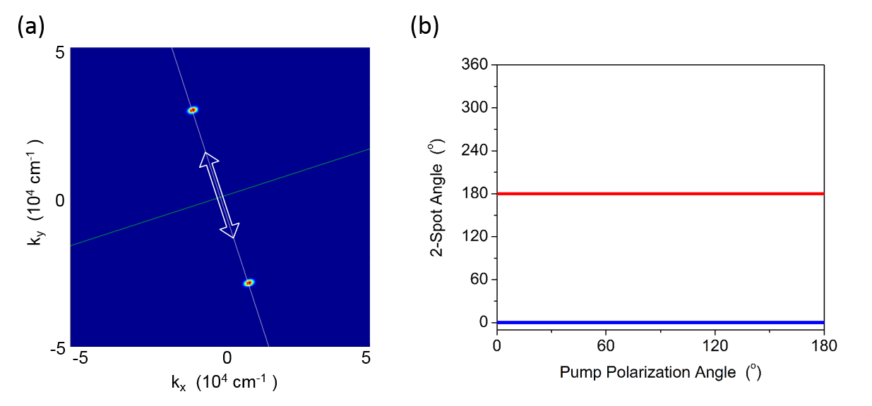
The pattern shape depends on the choice in the cavity asymmetry and pump power: The 2-spot pattern of figure 2 is obtained for a particular choice in the cavity asymmetry () and the pump power. If we choose a symmetric cavity or larger pump powers, we can also obtain a 6-spot pattern with a angle between the output fields. Which angles can occur in principle is determined by the nonlinearity, in our case a 3rd- order (or ) nonlinearity. The physical processes giving rise to the (2-spot) and angles (6-spot) are illustrated in Ref. 27. For a conventional single-cavity design, we have also found the possibility of angles 28 (4-spot) in the case of linearly polarized pump beams. These angles patterns are made possible by the interplay between the exciton-exciton interaction and TE-TM splitting. Interestingly, Whittaker et al. report on the experimental observation of a diverse family of polariton patterns, including ones with an odd number of lobes, by using circularly polarized excitation29. In their experiment as well, a pattern rotation was observed by changing from left to right circularly polarized pumping. We finally note that our model is for an optically isotropic crystal without strain or defects, so that the crystal orientation does not come into play in the selection of patterns and in their orientation.
3 Experimental setup and observations
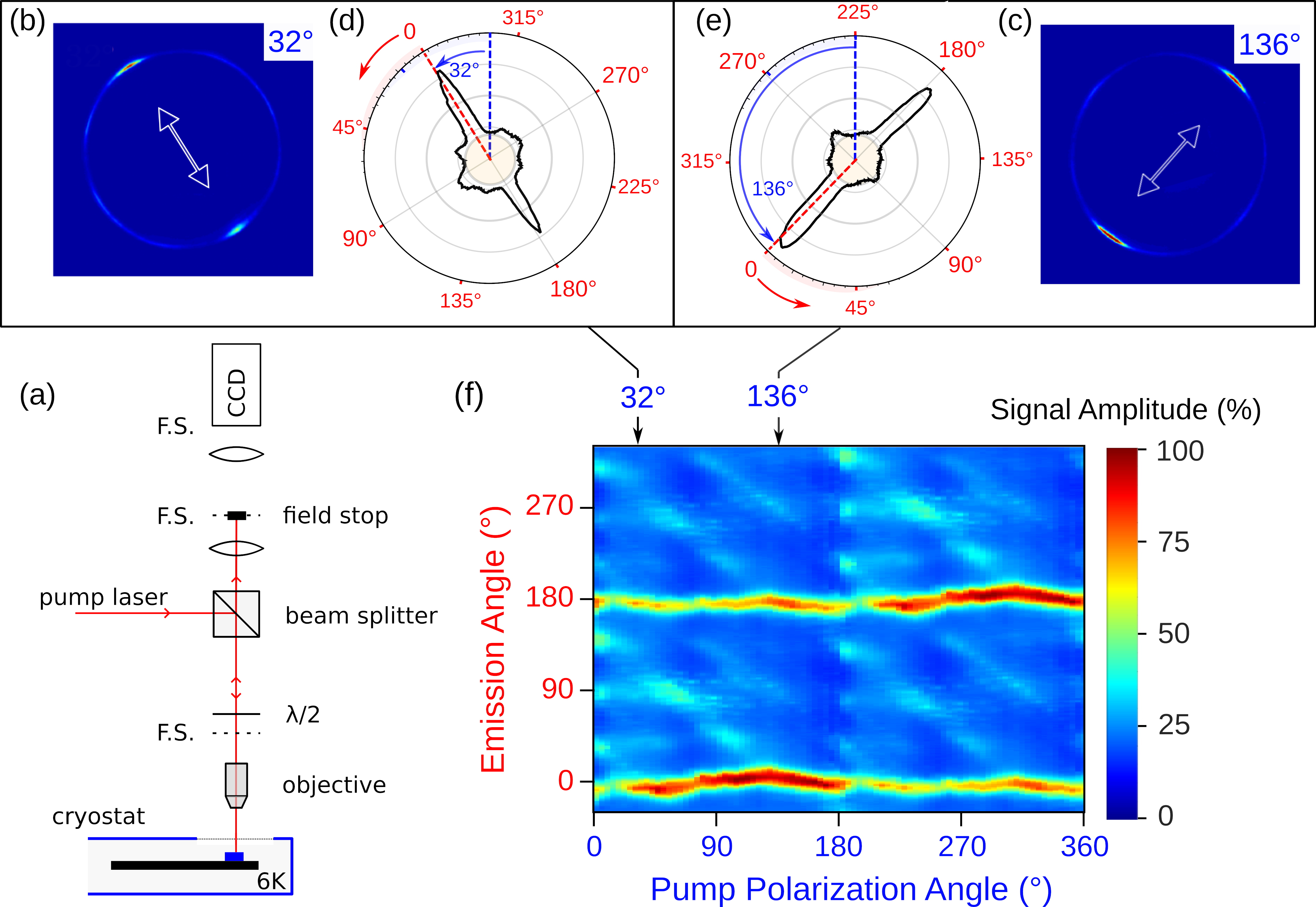
The sample, which has been used in several studies 12, 30, 31, 32, consists of two coupled Ga0.05Al0.95As cavities embedded between three Ga0.05Al0.95As/Ga0.8Al0.2As distributed Bragg reflectors with 25 (back), 17.5 (middle), and 17.5 (front) pairs respectively (fig. 1b). The nominal Q factor is , and the middle Bragg mirror induces a coupling between bare cavity modes. In each cavity, three sets of four GaAs QWs are inserted at the antinodes of the field, resulting in a Rabi splitting. Experiments are performed at , the sample is excited at normal incidence, in resonance with the lower polariton branch 2 (see fig. 1c), with a linearly polarized single-mode Ti:Sapphire laser. The pump polarization is controlled by a half-wave plate, and the far field is recorded in reflection geometry in the polarization orthogonal to the pump. The pump reflection is spatially filtered.
With a -wide resonant excitation beam, we observe the optical parametric oscillation (OPO) regime above an incoming laser power of and the structuration of the far field in a variety of light patterns 12. The two-spot patterns are the simplest of them and are observed just above OPO threshold, when the LP2 branch is slightly negatively detuned with respect to the bare exciton energy ().
Figure 3 represents the observed far-field emission of the microcavity (3a) and the corresponding radiation pattern (3b) that is observed at a radial angle of . This lighthouse-like emission is always directed along the linear pump polarization, independently of the crystal orientation, as evidenced by the direction emission map in Fig. 3c.
4 Discussion
Let us now discuss the experimental observations in light of the theoretical prediction of a lighthouse-like emission. Since the polariton lighthouse effect implies both a directional and controllable emission, we are going to analyze these two aspects.
The radiation patterns are approximately symmetric and highly directional: In the radial direction, the lighthouse emission is well focused with a beam width of only . This feature results from the strong constraint on radial emission set by the phase-matching conditions on resonant parametric scattering between the two lower polaritonic branches. In the azimuthal direction, the beam width is independent of the excitation linear polarization configuration.
In contrast, the theoretical prediction on figure 2 suggests much tighter azimuthal focusing is possible. This discrepancy probably originates from the effect of elastic scattering on line defects within the DBRs, which are signaled by a characteristic speckle signature in the elastically scattered signal (not shown). Indeed, whereas polariton-polariton parametric scattering in a uniform planar microcavity preserves total momentum, additional random elastic scattering lifts this restriction.
Most of the emission is cast in the two main lobes. The main lobes apparent imbalance results from a partial field stop within the large NA collecting objective. Stray light accounts for and has two origins: First, the resonant elastic scattering on DBR defects, which forms a direction independent background (yellow disk on fig. 3b) 31. Second, the competing parametric scattering pathways which are responsible for the formation of structured side lobes. Figure 3b) gives a representative example of radiation pattern (incoming polarization at with the [100] crystalline axis), as well as the most selective configuration (). From figure 3c), we see that side lobes are most pronounced when the incoming polarization is oriented along the [100] direction. This anisotropic response is most probably the result of residual built-in strain effects within the heterostructure.33, 34 We note that a clear lighthouse effect is evidenced over 90% of the incoming polarization angles and that the two-spot emission always dominate side lobes emission.
The angular precision of the lighthouse emission by the linear polarization is achieved with a remarkably high accuracy of . Previous work using InGaAs/GaAs microcavities presented strong anisotropic line defects and mosaicity which pinned the OPO emission on the semiconductor crystalline axes35. Therefore, we conclude that the small lattice mismatch of AlGaAs/GaAs microcavities is critical to achieve controllability of the emission.
The maximum emitted power in the main pattern reaches , which is only of the incoming power (, necessary to reach OPO threshold). This currently low external power efficiency (emitted power/incident power) is due to the fact that a strong Kerr effect occurs at resonance. As a result, the microcavity LP2 resonance is repelled from the excitation laser energy and most of the incoming power gets reflected on the first DBR and does not enter the microcavity. 36 By taking into account the low injection efficiency, we estimate that the internal power efficiency (emitted power/transmitted power) is in the range, whereas the theoretical limit is due to power balance between parametrically scattered beams in the OPO regime.
5 Conclusion
We have shown that an optical microcavity can present lighthouse-like emission continuously controlled by the linear vectorial polarization of the pump laser itself. The use of vectorial polarization as a control parameter implies that this function can only be implemented in a nonlinear optical device.
We used a coupled cavity theory combined with a many-particle theory describing exciton-exciton interactions to demonstrate the polariton lighthouse effect if a minimal set of physical ingredients are included, namely the nonlinear optical response of microcavity exciton-polaritons, the difference in the subcavities forming the microcavity, and the rotational invariance of the device. We observed the lighthouse effect with a device made of quantum wells embedded in a double microcavity and evidenced that a two-spot pattern oriented along the linear incoming pump polarization is observed for most azimuth angles with good control on the emission direction.
With our present cavity, we observe some deviations from the ideal lighthouse emission, such as parasitic stray light, originating from elastic scattering on line defects and the effect of built-in strain, and inherent to real world devices. Progresses in heterostructures quality and power efficiency could turn this polariton lighthouse effect into an original and useful all-optical beam-steering method which can be of great interest for microscopy or LIDARs.
We acknowledge that this project has received funding from the Agence Nationale de la Recherche (ANR) (ANR-16-CE24-0023 TeraMicroCav), the US National Science Foundation (NSF) (DMR 1839570), and the Deutsche Forschungsgemeinschaft (SCHU 1980/5-2 and Heisenberg grant 270619725). RB acknowledges CPU time at HPC (University of Arizona); SS acknowledges computing time at Paderborn Center for Parallel Computing ().
The microcavity geometry is detailed in section 3. During fabrication by molecular beam epitaxy, a wedge in the cavity thicknesses is introduced by stopping the cavity rotation during growth of the cavity layers. As a consequence, the sample has a natural gradient in the bare cavity energy, while the confined exciton energy is mostly unaffected. Note that upper and lower cavities have a parallel gradient in energy so that the coupled cavity modes inherit the same energy gradient. By recording the photoluminescence of lower polariton branches 1 and 2 on the sample surface, we can reconstruct the polariton anticrossing curve and characterize the polariton key properties of the sample. Figure 4a shows a typical dispersion curve obtained by photoluminescence, where only the two lower polariton branches (labeled LPB1 and LPB2) are visible. Lower polariton energies at normal incidence are represented function of the position on the sample along the gradient direction on figure 4b, the position corresponding to panel a is indicated as green points.
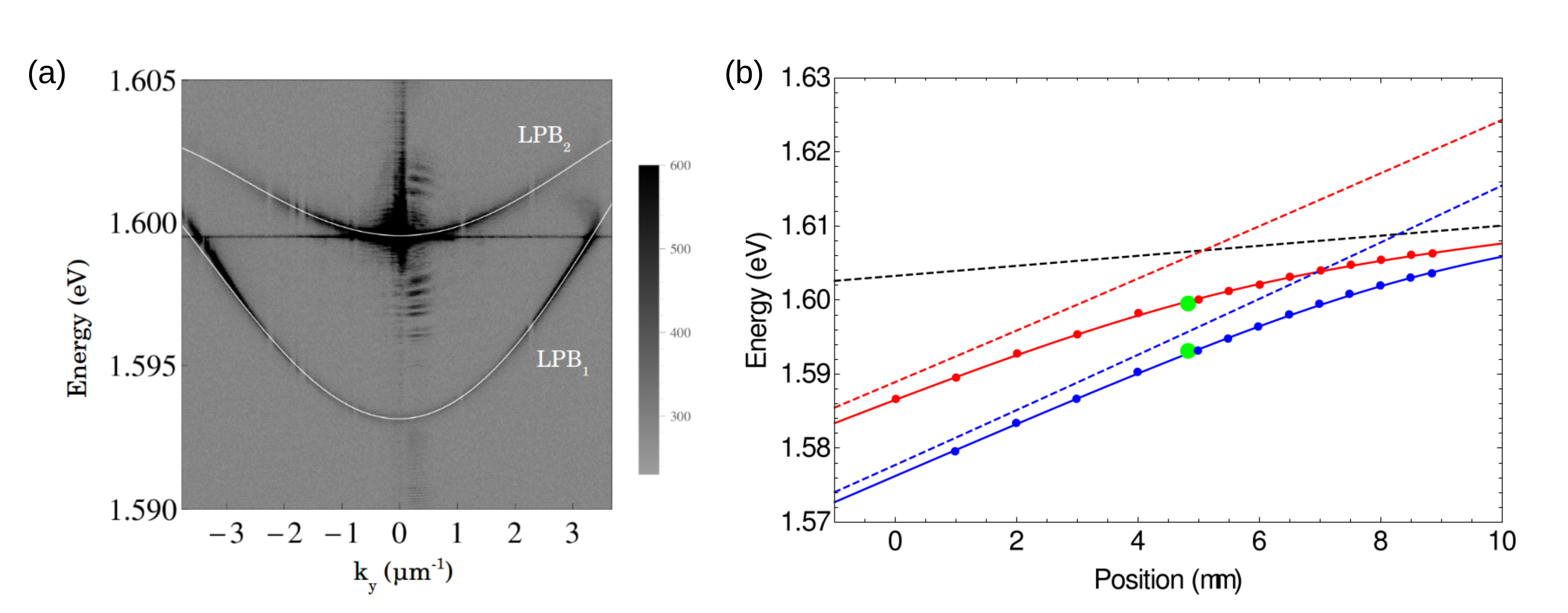
The two lower polariton branches of figure 4b are fitted by
where is the coupled cavity mode forming the polariton of interest, and both and evolves linearly with position on the sample. From these data we infer the cavity energy gradient of , the exciton energy , and the Rabi coupling , which is half the Rabi splitting between the lower and upper polaritons. From the coupled cavity splitting, we also deduce the coupling between the upper and lower microcavities .
References
- Visser 2006 Visser, H. J. Array and phased array antenna basics; John Wiley & Sons, 2006; DOI:10.1002/0470871199
- Sun et al. 2013 Sun, J.; Timurdogan, E.; Yaacobi, A.; Hosseini, E. S.; Watts, M. R. Large-scale nanophotonic phased array. Nature 2013, 493, 195–199
- Jarrahi et al. 2008 Jarrahi, M.; Pease, R. F. W.; Miller, D. A.; Lee, T. H. Optical switching based on high-speed phased array optical beam steering. Appl. Phys. Lett. 2008, 92, 014106
- Hulme et al. 2015 Hulme, J.; Doylend, J.; Heck, M.; Peters, J.; Davenport, M.; Bovington, J.; Coldren, L.; Bowers, J. Fully integrated hybrid silicon two dimensional beam scanner. Opt. Express 2015, 23, 5861–5874
- Hutchison et al. 2016 Hutchison, D. N.; Sun, J.; Doylend, J. K.; Kumar, R.; Heck, J.; Kim, W.; Phare, C. T.; Feshali, A.; Rong, H. High-resolution aliasing-free optical beam steering. Optica 2016, 3, 887–890
- Cao et al. 1994 Cao, X.; Meyerhofer, D.; Agrawal, G. Optimization of optical beam steering in nonlinear Kerr media by spatial phase modulation. J. Opt. Soc. Am. B 1994, 11, 2224–2231
- Rosberg et al. 2006 Rosberg, C. R.; Garanovich, I. L.; Sukhorukov, A. A.; Neshev, D. N.; Krolikowski, W.; Kivshar, Y. S. Demonstration of all-optical beam steering in modulated photonic lattices. Opt. Lett. 2006, 31, 1498–1500
- Shwartz et al. 2004 Shwartz, S.; Segev, M.; El-Hanany, U. Self-deflection and all-optical beam steering in CdZnTe. Opt. Lett. 2004, 29, 760–762
- Wheeler et al. 2012 Wheeler, J. A.; Borot, A.; Monchocé, S.; Vincenti, H.; Ricci, A.; Malvache, A.; Lopez-Martens, R.; Quéré, F. Attosecond lighthouses from plasma mirrors. Nat. Photonics 2012, 6, 829
- Liew et al. 2014 Liew, S. F.; Redding, B.; Ge, L.; Solomon, G. S.; Cao, H. Active control of emission directionality of semiconductor microdisk lasers. Appl. Phys. Lett. 2014, 104, 231108
- Bittner et al. 2018 Bittner, S.; Loirette-Pelous, A.; Lafargue, C.; Gozhyk, I.; Ulysse, C.; Dietz, B.; Zyss, J.; Lebental, M. Dynamical control of the emission of a square microlaser via symmetry classes. Phys. Rev. A 2018, 97, 043826
- Ardizzone et al. 2013 Ardizzone, V. et al. Formation and control of Turing patterns in a coherent quantum fluid. Sci. Rep. 2013, 3, 3016
- Weisbuch et al. 1992 Weisbuch, C.; Nishioka, M.; Ishikawa, A.; Arakawa, Y. Observation of the coupled exciton-photon mode splitting in a semiconductor quantum microcavity. Phys. Rev. Lett. 1992, 69, 3314
- Sanvitto and Timofeev 2012 Sanvitto, D.; Timofeev, V. Exciton Polaritons in Microcavities: New Frontiers; Springer Science & Business Media, 2012; Vol. 172
- Kavokin et al. 2017 Kavokin, A.; Baumberg, J. J.; Malpuech, G.; Laussy, F. P. Microcavities; Oxford University Press, 2017; DOI:10.1093/oso/9780198782995.001.0001
- Kuwata-Gonokami et al. 1997 Kuwata-Gonokami, M.; Inouye, S.; Suzuura, H.; Shirane, M.; Shimano, R.; Someya, T.; Sakaki, H. Parametric scattering of cavity polaritons. Phys. Rev. Lett. 1997, 79, 1341
- Savvidis et al. 2000 Savvidis, P.; Baumberg, J.; Stevenson, R.; Skolnick, M.; Whittaker, D.; Roberts, J. Angle-resonant stimulated polariton amplifier. Phys. Rev. Lett. 2000, 84, 1547
- Huang et al. 2000 Huang, R.; Tassone, F.; Yamamoto, Y. Experimental evidence of stimulated scattering of excitons into microcavity polaritons. Phys. Rev. B 2000, 61, 7854
- Ciuti et al. 2000 Ciuti, C.; Schwendimann, P.; Deveaud, B.; Quattropani, A. Theory of the angle-resonant polariton amplifier. Phys. Rev. B 2000, 62, 4825
- Stevenson et al. 2000 Stevenson, R.; Astratov, V.; Skolnick, M.; Whittaker, D.; Emam-Ismail, M.; Tartakovskii, A.; Savvidis, P.; Baumberg, J.; Roberts, J. Continuous wave observation of massive polariton redistribution by stimulated scattering in semiconductor microcavities. Phys. Rev. Lett. 2000, 85, 3680
- Langbein 2004 Langbein, W. Spontaneous parametric scattering of microcavity polaritons in momentum space. Phys. Rev. B 2004, 70, 205301
- Kwong et al. 2016 Kwong, N. H.; Tsang, C. Y.; Luk, M. H.; Tse, Y. C.; Lewandowski, P.; Chan, C. K. P.; Leueng, P. T.; Schumacher, S.; Binder, R. Patterns and switching dynamics in polaritonic quantum fluids in semiconductor microcavities. J. Opt. Soc. Am. B 2016, 33, 153–159
- Axt and Stahl 1994 Axt, V. M.; Stahl, A. A dynamics-controlled truncation scheme for the hierarchy of density matrices in semiconductor optics. Z. Phys. B 1994, 93, 195–204
- Takayama et al. 2002 Takayama, R.; Kwong, N. H.; Rumyantsev, I.; Kuwata-Gonokami, M.; Binder, R. T-matrix analysis of biexcitonic correlations in the nonlinear optical response of semiconductor quantum wells. Eur. Phys. J. B 2002, 25, 445–462
- Schumacher et al. 2007 Schumacher, S.; Kwong, N. H.; Binder, R. Influence of exciton-exciton correlations on the polarization characteristics of polariton amplification in semiconductor microcavities. Phys. Rev. B 2007, 76, 245324
- Luk 2018 Luk, M. H. Pattern Generation and Control in Semiconductor Quantum Well Microcavities. Ph.D. thesis, The University of Arizona, 2018; available at https://repository.arizona.edu/handle/10150/628051
- Kwong et al. 2017 Kwong, N. H.; Tsang, C. Y.; Luk, M. H.; Tse, Y. C.; Chan, C.; Lewandowski, P.; Leung, P. T.; Schumacher, S.; Binder, R. Optical switching of polariton density patterns in semiconductor microcavity. Phys. Scr. 2017, 92, 034006 – (10)
- Lewandowski et al. 2017 Lewandowski, P.; Luk, S. M. H.; Chan, C. K. P.; Leung, P. T.; Kwong, N. H.; Binder, R.; Schumacher, S. Directional optical switching and transistor functionality using optical parametric oscillation in a spinor polariton fluid. Opt. Express 2017, 25, 31056 –(8)
- Whittaker et al. 2017 Whittaker, C. E.; Dzurnak, B.; Egorov, O. A.; Buonaiuto, G.; Walker, P. M.; Cancellieri, E.; Whittaker, D. M.; Clarke, E.; Gavrilov, S. S.; Skolnick, M. S.; Krizhanovskii, D. N. Polariton pattern formation and photon statistics of the associated emission. Phys. Rev. X 2017, 7, 031033
- Lafont et al. 2017 Lafont, O.; Luk, S.; Lewandowski, P.; Kwong, N.; Leung, P.; Galopin, E.; Lemaitre, A.; Tignon, J.; Schumacher, S.; Baudin, E.; Binder, R. Controlling the Optical Spin Hall Effect with Light. Appl. Phys. Lett. 2017, 110, 061108
- Lewandowski et al. 2016 Lewandowski, P.; Lafont, O.; Baudin, E.; Chan, C.; Leung, P.; Luk, S.; Galopin, E.; Lemaitre, A.; Bloch, J.; Tignon, J.; Roussignol, P.; Kwong, N.; Binder, R.; Schumacher, S. Polarization Dependence of Nonlinear Wave Mixing of Spinor Polaritons in Semiconductor Microcavities. Phys. Rev. B 2016, 94, 045308
- Luk et al. 2018 Luk, S. M. H.; Lewandowski, P.; Kwong, N. H.; Baudin, E.; Lafont, O.; Tignon, J.; Leung, P. T.; Chan, C. K. P.; Babilon, M.; Schumacher, S.; Binder, R. Theory of Optically Controlled Anisotropic Polariton Transport in Semiconductor Double Microcavities. J. Opt. Soc. Am. B 2018, 35, 146–155
- Dasbach et al. 2002 Dasbach, G.; Dremin, A.; Bayer, M.; Kulakovskii, V.; Gippius, N.; Forchel, A. Oscillations in the differential transmission of a semiconductor microcavity with reduced symmetry. Phys. Rev. B 2002, 65, 245316
- Lafont et al. 2016 Lafont, O.; Ardizzone, V.; Lemaître, A.; Sagnes, I.; Senellart, P.; Bloch, J.; Tignon, J.; Roussignol, P.; Baudin, E. Origins and control of the polarization splitting in exciton-polaritons microwires. arXiv preprint arXiv:1610.04856 2016,
- Abbarchi et al. 2012 Abbarchi, M.; Diederichs, C.; Largeau, L.; Ardizzone, V.; Mauguin, O.; Lecomte, T.; Lemaitre, A.; Bloch, J.; Roussignol, P.; Tignon, J. Discretized Disorder in Planar Semiconductor Microcavities: Mosaicity Effect on Resonant Rayleigh Scattering and Optical Parametric Oscillation. Phys. Rev. B 2012, 85, 045316
- Baas et al. 2004 Baas, A.; Karr, J. P.; Eleuch, H.; Giacobino, E. Optical bistability in semiconductor microcavities. Phys. Rev. A 2004, 69, 023809