Reconfigurable Intelligent Surfaces with Reflection Pattern Modulation: Beamforming Design and Performance Analysis
Abstract
Recent considerations for reconfigurable intelligent surfaces (RISs) assume that RISs can convey information by reflection without the need of transmit radio frequency chains, which, however, is a challenging task. In this paper, we propose an RIS-enhanced multiple-input single-output system with reflection pattern modulation, where the RIS can configure its reflection state for boosting the received signal power via passive beamforming and simultaneously conveying its own information via reflection. We formulate an optimization problem to maximize the average received signal power by jointly optimizing the active beamforming at the access point (AP) and passive beamforming at the RIS for the case where the RIS’s state information is statistically known by the AP, and propose a high-quality suboptimal solution based on the alternating optimization technique. We analyze the asymptotic outage probability of the proposed scheme under Rayleigh fading channels, for which a closed-form expression is derived. The achievable rate of the proposed scheme is also investigated for the case where the transmitted symbol is drawn from a finite constellation. Simulation results validate the effectiveness of the proposed scheme and reveal the effect of various system parameters on the achievable rate performance. It is shown that the proposed scheme outperforms the conventional RIS-assisted system without information transfer in terms of achievable rate performance.
Index Terms:
Reconfigurable intelligent surface (RIS), information transfer, metasurface, outage probability, passive beamforming, rate performance, reflection modulation.I Introduction
To meet the demanding requirements for fifth generation (5G) wireless communication in, e.g., enhanced data rate, massive connectivity, low latency, ultra reliability, etc., multiple key technologies including millimeter wave (mmWave) communications, massive multiple-input multiple-output (MIMO) systems, and ultra-dense networks (UDNs) have been extensively investigated in the last decade [1]. However, most of those technologies generally require increased implementation complexity and result in considerably increased energy consumption [2, 3]. Leveraging the recent advances in reconfigurable metasurfaces [4, 5], reconfigurable intelligent surfaces (RISs) (a.k.a. intelligent reflecting surfaces) have emerged as a revolutionary technology for improving the coverage and energy/spectrum efficiency of future wireless communications [6, 7, 8, 9, 10, 11, 12]. Specifically, RISs are planar metasurfaces consisting of a large number of low-cost unit cell elements, each of which reflects the incident signals according to its reflection state. By configuring the reflection amplitude and/or phase shift at each unit cell element according to the dynamic wireless channels, the signals reflected by the RIS can constructively or destructively combine with the signals from other paths at the receiver for signal power enhancement or co-channel interference suppression [13]. Compared to traditional relays, RISs are envisioned to work in a full-duplex mode without incurring self-interference and thermal noise, and yet possess substantially reduced hardware cost and energy consumption owing to their nearly passive components [14, 15, 16, 17].
To achieve the theoretical passive beamforming gain offered by RISs in RIS-assisted systems, the global channel state information (CSI) was assumed to be available at the RIS side [18], which is practically difficult to implement. The acquisition/estimation of channels involving RIS is in practice a challenging task due to the absence of signal processing capability of passive RISs and their large number of unit cell elements, which has spurred rapidly growing interests [19, 20, 21, 22, 23, 24, 25, 26]. Existing RIS channel acquisition methods can be classified into two categories. The first category [19, 20] includes the approaches considering that RISs are embedded with some receive radio frequency (RF) chains, which enable them to explicitly estimate the channels from the network’s transmitters/receivers to RIS. In the second category, instead of explicitly estimating the individual channels from the network’s transmitters/receivers to RIS, the cascaded transmitter-RIS-receiver channels are estimated at the receiver by adopting an element-by-element ON/OFF-based reflection pattern at RIS without the need of costly receive RF chains [22]. However, this approach incurs prohibitive channel estimation overhead due to the large number of RIS elements. To reduce the channel estimation overhead, a grouping strategy for the RIS elements was proposed in [24], where adjacent RIS elements are grouped together to share a common reflection coefficient. Based on this grouping strategy, a channel estimation method using the discrete Fourier transform (DFT)-based reflection pattern was first presented in [25] for frequency-selective fading channels, which significantly improves the channel estimation accuracy by leveraging the large aperture gain of RIS. In [27], a DFT-based reflection pattern was designed for channel estimation in RIS-assisted narrowband systems. More recently, some preliminary works (e.g., [28, 29]) have appeared for channel estimation in RIS-assisted multi-user systems.
Prior works on RISs mainly focus on their utilization for maximizing the received signal strength of links between the access point (AP) and users, e.g., [30]. In order to improve the spectral efficiency of RIS-assisted systems, the authors of [31] introduced the RIS-space shift keying and RIS-spatial modulation schemes to implement the index modulation at the receiver side. In addition, the authors of [32] proposed to jointly encode the information in the transmitted signal and RIS state for improving spectral efficiency. On the other hand, another type of the RIS-assisted system, in which the RIS needs to deliver its own information to the receiver, was considered in [33]. In this case, the RIS is equipped with sensors, such as temperature and/or humidity sensors, and has a requirement on conveying its locally acquired information to an intended receiver. Besides the information from sensors, there are other potential sources of RIS information, including the RIS control signaling, RIS maintenance data, estimated CSI at the RIS, etc., [20, 34]. One option for the information transfer of the RIS is to install multiple transmit RF chains, which, however, incurs much higher hardware cost and energy consumption as compared to the fully-passive RIS case [10]. Alternatively, when no transmit RF chain is installed at the RIS, its own information should be implicitly delivered via appropriately designed reflection state, which is a more cost-effective, yet challenging, solution. To this end, a passive beamforming and information transfer (PBIT) scheme was proposed in [35] and [36] to convey the RIS’s information besides implementing fully-passive beamforming. However, in this scheme, the number of activated (ON-state) elements111The ON/OFF switching of the RIS elements can be implemented by the switchers. varies over time, which can cause significant fluctuation in the reflected signal power, resulting in a relatively high outage probability.
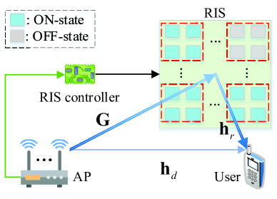
In this paper, we consider an RIS-enhanced multiple-input single-output (MISO) wireless communication system as shown in Fig. 1, where a multi-antenna AP communicates with a single-antenna user with the aid of an RIS. The RIS is explored as an efficient and inexpensive dual-use technology of passive beamforming and information transfer by proposing the concept of reflection pattern modulation (RPM). The core RPM idea is to activate a subset of RIS unit cell elements in order to reflect a sharp beam towards the intended destination, while exploiting the indices of the activated (ON-state) elements to implicitly convey the RIS’s information. The main contributions of this paper are summarized as follows:
-
•
We present an RIS-based RPM (RIS-RPM) scheme for PBIT, in which the RIS plays the following two roles: 1) it boosts the received signal power at the intended receiver; 2) it transfers via reflection its locally acquired information data. We consider the practical scenario where the ON/OFF state information of the RIS is statistically known by the AP, for which an optimization problem is formulated to maximize the average received signal power by jointly optimizing the active beamforming at the AP and passive beamforming at the RIS. The formulated problem, however, is non-convex and thus difficult to solve optimally. As such, we propose an efficient algorithm based on the alternating optimization technique to find a high-quality suboptimal solution. Moreover, we formulate and solve an optimization problem to maximize the instantaneous received signal power by designing the active and passive beamforming based on the RIS’s instantaneous ON/OFF state information, which serves as a performance upper bound for the practical beamforming design based on the RIS’s statistical ON/OFF state information.
-
•
The asymptotic outage probability of the proposed RIS-RPM scheme over Rayleigh fading channels is derived in closed-form. It is shown that the RIS is able to drastically increase the diversity gain by properly designing the phase shifts of its elements. Moreover, we analyze the achievable rate of the RIS-RPM scheme for the practical case where the transmitted symbol is drawn from a finite constellation input. Simulation results validate the effectiveness of the proposed RIS-RPM scheme as well as the proposed optimization algorithm, and unveil the effect of various system parameters on the achievable rate performance. It is shown that the RIS-RPM scheme outperforms the conventional RIS-assisted system with full-ON RIS reflection [18] in terms of achievable rate performance, despite the loss in the received signal strength. Moreover, the RIS-RPM scheme is shown to have the potential to strike an attractive trade-off between the received signal power and achievable rate performance by varying the number of activated (ON-state) RIS elements.
The rest of this paper is organized as follows. In Section II, we introduce the system model associated with channel acquisition. In Sections III and IV, we formulate two optimization problems for designing active and passive beamforming with efficient solutions. Performance analysis in terms of outage probability and achievable rate is presented in Section V. Simulation results are presented in Section VI and conclusions are drawn in Section VII.
Notation: Upper and lower case boldface letters denote matrices and column vectors, respectively. , , , and represent conjugation, transpose, Hermitian transpose, and inversion operations, respectively. denotes the ()-th entry of matrix , and denotes the -th entry of vector . denotes an identity matrix, and and denote -dimensional all-one and all-zero column vectors, respectively. and denote the zero norm and Euclidean norm of vector , respectively. denotes the set of complex-valued matrices. denotes a diagonal matrix with each diagonal entry being the corresponding entry in vector . and denote the trace and rank of matrix , respectively. and denote the modulus and phase of a complex number, respectively. denotes the probability density function (PDF). represents the ceiling function that returns the least integer greater than or equal to the argument. denotes the binomial coefficient. is the complement set of with respect to . denotes the distribution of a circularly symmetric complex Gaussian random vector with covariance matrix and mean . denotes the expectation over random variable . Let denote that a Hermitian matrix is positive semi-definite.
II System Description and Channel Estimation
As illustrated in Fig. 1, we consider a MISO wireless communication system, where an RIS composed of unit cell elements is deployed to enhance the communication link from an AP equipped with transmit antennas to a single-antenna user. An RIS controller is attached to the RIS, which is responsible for reconfiguring the phase shifts and/or reflection amplitudes of the unit cell elements [37] and exchanging information with the AP for the realization of the simultaneous passive beamforming and reflection modulation. We assume that the RIS controller is equipped with a number of sensors in order to monitor/collect environmental data, which is typically low-rate bursty data for the user. In this paper, we consider quasi-static block fading channels for the AP-user, AP-RIS, and RIS-user links, where all the channels remain unchanged over the coherence block equal to the duration of symbol sampling periods, and are independent and identically distributed (i.i.d.) across different coherence blocks. This assumption is valid since RISs are practically used to support low-mobility users in their vicinity.
II-A System Model
| Information bits of RIS | 00 | 01 | 10 | 11 | |
| Index of OFF-state element | {4} | {3} | {2} | {1} | |
|
|
|
|
|
For each symbol duration, only out of unit cell elements are turned ON to reflect incident signals on purpose so that the indices of those ON-state elements can implicitly convey the RIS information. With the proposed RPM scheme, there are in total combinations for determining the indices of ON-state elements at the RIS, such that information bits can be conveyed. An example of the proposed RPM scheme with an RIS of unit cell elements ( ON-state elements) is illustrated in Table I. However, the number of unit cell elements at the RIS can be practically large, leading to an enormous calculation and storage overhead in the combination mapping as the number of -combinations increases exponentially with . To address this issue, we adopt the RIS-elements grouping method, where a total number of unit cell elements are divided into groups, each of which consists of adjacent elements sharing a common reflection coefficient. For notational convenience, we assume that is an integer that we refer to as the grouping size. As such, the information of the RIS is conveyed through the indices of the ON-state groups. Specifically, for each symbol duration, out of groups are randomly turned ON for reflecting the incident signals, and the remaining groups are deliberately turned OFF for realizing the proposed RPM scheme. Therefore, a total number of information bits can be conveyed. Let denote the indices of the ON-state groups, where for with . Given the indices of the ON-state groups, the common reflection coefficient for the -th group can be characterized by
| (3) |
where and represent the common reflection amplitude and phase shift for the -th group, respectively. To enhance the reflected signal power and ease the hardware design, the reflection amplitudes of the ON-state groups are set to be the maximum value, i.e., , . Let denote the RIS reflection vector after grouping, which characterizes the equivalent interaction of the RIS with the incident signals. According to (3), we have .
Let , , and denote the baseband channels from the AP to RIS, from the RIS to user, and from the AP to user, respectively, where and denote the corresponding channels associated with the RIS elements belonging to the -th group, respectively. Moreover, due to the severe path loss and high attenuation, the signals reflected by the RIS more than once have negligible power and hence can be ignored. Accordingly, the received signal at the user is given by
| (4) |
where is the maximum transmit power of the AP, stands for the active beamforming at the AP, is the transmitted symbol, which is drawn from an constellation with normalized power, is the common reflection coefficient for the -th group, and is the additive white Gaussian noise (AWGN) with being the noise power. Since RIS elements in the same group share a common reflection coefficient, by denoting as the equivalent cascaded channel of the AP-RIS-user link associated with the -th group without the effect of RIS reflection, (4) can be rewritten as
| (5) |
where denotes the cascaded AP-RIS-user channel matrix without the effect of RIS reflection. From (5), it can be observed that the information delivered to the user consists of two parts: the first part is from the AP explicitly expressed as and the second part is from the RIS implicitly embedded in .
II-B Channel Estimation
To boost the received signal power by jointly optimizing the active beamforming at the AP and passive beamforming at the RIS, the knowledge of and is required. By assuming channel reciprocity and using time-division duplex (TDD) protocol, the CSI of and can be obtained at the AP. Specifically, during the channel training, consecutive pilot symbols are sent by the user. For the duration of the -th () pilot symbol, the received pilot signal vector at the AP can be expressed as
| (6) |
where is the transmit power of the user, is the -th pilot symbol with normalized power, is the common phase shift for the -th group during the transmission of the -th pilot symbol with , and is the AWGN vector. By letting denote the RIS phase-shift state during the transmission of the -th pilot symbol, (6) can be rewritten as
| (7) |
where and . By stacking consecutive received pilot signals, we have
| (8) |
where is the RIS phase-shift pattern, denotes the pilot sequence, and is the AWGN matrix. By using the DFT-based phase-shift pattern [27], the CSI of and can be estimated as
| (9) |
where , .
After acquiring the CSI of and , the AP jointly optimizes the active beamforming and phase shifts of all RIS-elements groups to boost the received signal power, and then informs the RIS controller the optimized phase shifts to be implemented at the corresponding unit cell elements. In the following section, we formulate an optimization problem to maximize the average received signal power by jointly designing the active beamforming at the AP and passive beamforming at the RIS based on the statistical ON/OFF state information of the RIS.
III Beamforming Design Based on Statistical ON/OFF State Information
III-A Problem Formulation
We consider the practical assumption that the ON/OFF state information of the RIS is statistically known by the AP. Our objective is to minimize the outage probability of the combined AP-user channel by jointly optimizing the active beamforming at the AP and passive beamforming at the RIS under the constraints of the maximum transmit power of the AP and unit-modulus reflection of the RIS. Specifically, given the indices of the ON-state groups , let denote the ON/OFF states of all RIS-elements groups in a vector form, with each entry given by
| (12) |
where and represent the ON and OFF states, respectively. Based on (12), the RIS reflection vector can be rewritten as , in which is the diagonal phase-shift matrix of the RIS with the -th diagonal entry given by , , . The combined channel from the AP to user is given as , and thus the achievable rate of the combined AP-user channel conditioned on and can be expressed as bits/second/Hertz. The corresponding outage probability for a fixed rate is given by
| (13) |
The optimization problem for minimizing the outage probability in (13) under the constraints of the maximum transmit power of AP and unit-modulus reflection of RIS can be formulated as
| (14) | ||||
| s.t. | (15) | |||
| (16) | ||||
| (17) |
However, this problem is non-convex and difficult to solve due to the robust outage probability and unit-modulus constraint. On the other hand, it can be observed from (9) that given any ON/OFF-state vector , we should optimize the active beamforming at the AP and passive beamforming at the RIS to maximize the received signal power for minimizing the outage probability. However, since the instantaneous ON/OFF state information of the RIS is unavailable to the AP, we instead optimize the active beamforming and passive beamforming to maximize the average received signal power. Note that this is effective in improving the performance in terms of outage probability, as will be shown in our simulations. Let and denote the covariance matrix and mean vector of , respectively. Based on (12) and assuming that all possible index combinations are equiprobable, the elements of and can be derived as follows.
| (20) |
and
| (21) |
Thus, the average received signal power normalized by the transmit power is given by
| (28) |
Accordingly, the corresponding optimization problem based on the estimated CSI of and is formulated as:
| (33) | ||||
| s.t. | (34) | |||
| (35) |
It can be readily verified that problem (P1) is a non-convex problem as well, since the objective function of (33) is non-concave with respect to both and , and the constraint in (35) is not convex. Moreover, due to the mutual coupling between and in the objective function of (33), problem (P1) becomes even more difficult to solve. To circumvent the above difficulties, we develop an alternating optimization algorithm to find a high-quality suboptimal solution to problem (P1) in the following, which iteratively optimizes one of and with the other being fixed at each time for decoupling the original problem.
III-B Joint Beamforming Design
Input: , , threshold , and the maximum iteration number
Output: and
For any given RIS phase-shift matrix , problem (P1) can be rewritten as
| (36) | ||||
| s.t. | (37) |
where
| (42) |
Since is Hermitian, for any non-zero , we have the following inequality
| (43) |
where denote the maximum eigenvalue of . Let denote the eigenvector corresponding to the maximum eigenvalue of . Then, it can be readily verified that the optimal solution to problem (P1.1) is given by .
Next, we optimize based on the given active beamforming . Specifically, for given , by letting and , problem (P1) can be rewritten as follows (omitted irrelevant terms for brevity).
| (44) | ||||
| s.t. | (45) |
From (44) and (45), we see that problem (P1.2) is a non-convex quadratically constrained quadratic program (QCQP), which can be reformulated as a homogeneous QCQP by introducing an auxiliary variable [38], i.e.,
| (46) | ||||
| s.t. | (47) |
where
| (52) |
The objective function of (46) can be rewritten as with . Note that is a positive semidefinite matrix with . However, as the rank-one constraint is non-convex, we apply the semidefinite relaxation (SDR) method to relax this constraint and reformulate problem (P1.3) as
| (53) | ||||
| s.t. | (54) | |||
| (55) |
which is a standard convex semidefinite programming (SDP) problem and can be well solved via existing convex optimization solvers such as CVX [39]. It is worth pointing out that after the relaxation, the optimal solution to problem (P1.4) may not be a rank-one solution. Therefore, we retrieve from as follows.
| (58) |
where is the eigenvalue decomposition of and is a random vector. Finally, the suboptimal solution to problem (P1.2) is given by
| (59) |
The algorithm proceeds by iteratively solving subproblems (P1.1) and (P1.4) in an alternating manner until the convergence criterion is met, i.e., the fractional increase of (33) is less than a small positive number , or the maximum number of iterations has been carried out in practice. Algorithm 1 summarizes the above procedures. The convergence of the proposed algorithm can be guaranteed by the fact that the objective value of problem (P1) is non-decreasing over iterations and upper-bounded by a finite value due to the limited transmit power. On the other hand, problem (P1.1) involving the eigenvalue decomposition of an matrix can be solved with a complexity of , and the SDP problem (P1.4) can be solved with a worst-case complexity of [40]. Given the number of iterations , the total complexity for solving problem (P1) is thus given by . After getting the optimized phase-shift vector , the RIS performs passive beamforming with only (while the RIS elements belonging to the remaining groups are set to be OFF, i.e., =) according to the selection of by RIS.
IV Beamforming Design Based on Instantaneous ON/OFF State Information
In this section, we characterize the upper bound on the received signal power, which serves to compare the above beamforming design based on the statistical ON/OFF state information of the RIS. We assume that the AP knows the ON/OFF state information of the RIS exactly in real time. It is worth mentioning that this assumption is similar to that in [32]. Under this assumption, we formulate an optimization problem to maximize the received signal power by jointly designing the active beamforming at the AP and passive beamforming at the RIS based on instantaneous ON/OFF state information of the RIS.
Given the indices of the ON-state groups , the corresponding optimization problem based on the estimated CSI can be formulated as follows (with omitted for brevity).
| (60) | ||||
| s.t. | (61) | |||
| (62) | ||||
| (63) |
By eliminating the constraint of (63), problem (P2) is equivalent to
| (64) | ||||
| s.t. | (65) | |||
| (66) |
where is the sub-vector consisting of the entries of indexed by , and is the sub-matrix consisting of the rows of indexed by . It can be readily verified that problem (P2.1) is non-convex as well, since the objective function of (64) is non-concave with respect to both and , as well as the constraint of (66) is not convex. Apparently, problem (P2.1) can be solved suboptimally by leveraging the alternating optimization technique similarly to Algorithm 1. Specifically, based on the alternating optimization technique, one of and is optimized with the other being fixed in each iteration. For given active beamforming , problem (P2.1) can be reformulated as
| (67) | ||||
| s.t. | (68) |
By exploiting the triangle inequality, we have
| (69) |
with equality if and only if for all . Therefore, the optimal phase shift for the -th () ON-state group is given by
| (70) |
For given in (70), it can be readily obtained that the optimal active beamforming is given by
| (71) |
which is the well-known maximum-ratio transmission (MRT). and are iteratively optimized according to (70) and (71) in an alternating manner until the convergence criterion is met. Note that the above solution is guaranteed to converge since the objective value of problem (P2) is non-decreasing over iterations and the optimal objective value of problem (P2) is finite.
V Performance Analysis
In this section, we investigate the proposed RIS-RPM scheme in terms of the outage probability and achievable rate.
V-A Outage Probability
For ease of exposition, we assume with and , such that the active beamforming vector can be dropped. Moreover, we consider the Rician fading channel model for all the channels involved, where each channel coefficient equals the superposition of a determined line-of-sight (LoS) component and a non-LoS component (characterized by a complex Gaussian random variable). Let , , and denote the Rician factors of the AP-RIS, RIS-user, and AP-user links, respectively. In particular, the RIS is generally installed on the walls/ceilings to establish a LoS link with the AP to boost the signal strength in its vicinity, while the user is usually in a relatively rich scattering environment. Therefore, we assume , , and , so that the AP-RIS channel has only a fixed LoS component while the AP-user and RIS-user channels can be well characterized by Rayleigh fading. Let denote the power in the LoS component of the AP-RIS channel and assume as well as . As such, we have with . For ease of notation, we assume . Moreover, we resort to a unified definition of signal-to-noise ratio (SNR) as to draw essential insights. Then the outage probability in (13) can be simplified as
| (72) |
Let and . First, we assume perfect CSI available at the AP for setting the phase shifts of RIS elements. The optimal phase shifts for are solutions that arrange the signals reflected by RIS elements to align in phase with the signal over the direct link at the user, regardless of the ON/OFF-state information of the RIS. Thus, we have , where are i.i.d. Rayleigh random variables with parameter . Let , which is the square of the sum of independent Rayleigh random variables and has a Gamma distribution with parameters
| (73) |
where
| (74) | ||||
| (75) |
Its probability density function is
| (76) |
Approximating by for , we have
| (77) |
for a small positive value . Hence at high SNR the outage probability can be approximated by
| (78) |
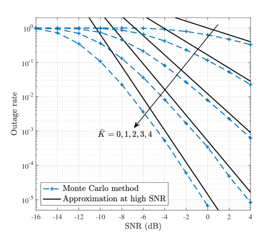
From (78), we see a diversity gain of . It can be readily verified that linearly increases with and satisfies with equality if and only if . As shown in Fig. 2, tracks very well the trend of in the high SNR region, and the increase of leads to an increase in the diversity gain.
Next, we consider the benchmark case with unit phase shifts at the RIS, i.e., , which does not require any CSI for setting the phase shifts and thus can dispense with the channel acquisition. In this case, is the square of the sum of independent random variables and follows Gamma distribution with parameters and . Hence at high SNR the outage probability with the unit phase shift design can be approximated by
| (79) |
Comparing (78) with (79), we can see an increase in the diversity gain due to the properly designed RIS phase shifts.
V-B Achievable Rate
For practical implementation, constellation is typically a finite and discrete complex signal set of cardinality with normalized power, i.e., with , where the constellation points are independent and equiprobable. Let denote the index set of all the possible combinations of the ON-state groups with the cardinality of , where is the element of set representing the -th index combination realization. Assume that all the combination realizations in are independent and equiprobable.
V-B1 Beamforming Design Based on Statistical ON/OFF State Information
First, we focus on the RIS-RPM scheme with the practical beamforming design based on statistical ON/OFF state information of the RIS. We rewrite the system model of (5) as
| (80) |
Let , whose entries are the effective channels of the cascaded AP-RIS-user links perceived by the user associated with the corresponding RIS-elements groups. Let denote the effective channel of the direct AP-user link perceived by the user. Before recovering the information to be sent by the AP and RIS, the user generally has to acquire the knowledge of and . Note that the knowledge of can be obtained at the user based on downlink pilot training by using as the RIS reflection pattern, while the knowledge of can be obtained by applying conventional channel estimation methods with all RIS-elements groups turned OFF. Therefore, we assume that the knowledge of and is available at the user side, and the achievable rate of the RIS-RPM scheme with the practical beamforming design is given by
| (81) |
where denotes the mutual information between the random vector and random variable .
| (82) |
Proposition 1.
The achievable rate of the RIS-RPM scheme with the practical beamforming design is given by (V-B1), which is shown at the top of the page, where is a complex Gaussian random variable following .
Proof.
According to the definition of mutual information, (81) can be derived as
| (83) |
where and denote the marginal entropy and conditional entropy, respectively. Due to the independence between the selection of and symbol modulation at the AP, we have . The last term at the right hand side of (83) can be expressed according to the definition of conditional entropy as
| (84) |
where
| (85) |
and
| (86) |
Replacing with yields
| (87) |
where is the PDF of a complex Gaussian random variable with zero mean and variance . Since the last term at the right hand side of (V-B1) is the differential entropy of a random variable, which is equal to , we finally obtain the expression of as (V-B1). ∎
V-B2 Beamforming Design Based on Instantaneous ON/OFF State Information
Next, we characterize the upper bound on the achievable rate of the RIS-RPM scheme, where the active and passive beamforming vectors are optimized based on the instantaneous ON/OFF state information of the RIS. In this case, beamforming and highly depend on the selection of . Define
| (88) |
which is the effective channel perceived by the user and can be obtained by downlink channel training. By assuming that the knowledge of is available at the user side, the achievable rate of the RIS-RPM scheme with the beamforming design presented in Section IV is given by
| (89) |
Proposition 2.
| (90) |
Proof.
The proof is similar to (V-B1) and omitted for brevity. ∎
VI Simulation Results and Discussions
In this section, simulation results are presented to evaluate the performance of our proposed schemes. We consider a three dimensional coordinate system, where the centers of the AP and RIS are located at and , respectively, and the user is located at . For the AP, we consider a uniform linear array of antennas with an antenna spacing of half-wavelength, located in -axis. For the RIS, we consider a uniform square array of elements with an element spacing of half-wavelength, deployed in - plane. The fading channel model for all the channels involved is given by
where is the Rician factor, is the path loss, is the signal propagation distance, and is the signal wavelength. We resort to the simplified path loss model, i.e., , where is the path loss at a reference distance of 1 meter (m), and is the path loss exponent. The Rician factors of the AP-user, AP-RIS, and RIS-user links are set as , , and , respectively, as in Section V-A. The path loss exponents of the AP-user, AP-RIS, and RIS-user links are set as 3.8, 2.2, and 2.4, respectively. The noise power is set as dBm. Other parameters are set as follows: m, m, m, symbol sampling periods, dB, and quadrature phase-shift keying (QPSK) for symbol modulation at the AP. We consider the Zadoff-Chu sequence as the pilot sequence and set dBm for channel estimation. The maximum iteration number in Algorithm 1 is set as and the threshold is set as . The values of and as well as the AP’s transmit power level will be specified later to study their effects on the system performance. In the following simulations, the results are obtained by averaging over more than independent channel realizations.
VI-A Performance of Algorithm 1
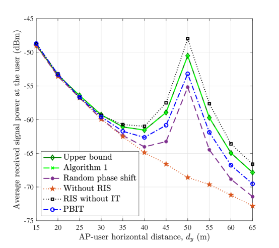
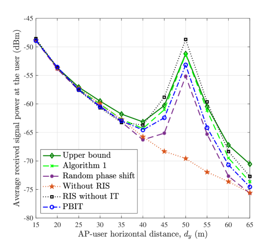
To evaluate the effectiveness of Algorithm 1, we consider the following schemes with fixed and dBm: 1) Benchmark scheme without information transfer (IT) [18] where all RIS elements are turned ON and problem (P2) with is solved to obtain the active and passive beamforming vectors; 2) Conventional MISO scheme without RIS in which ; 3) Random phase shift scheme where the phase shifts of diagonal entries in are randomly drawn from and then problem (P1.1) is solved to obtain the active beamforming vector; 4) Upper bound that solves problem (P2); 5) PBIT scheme where elements in the ON/OFF-state vector are independently drawn from the set with equal probability. For the PBIT scheme, the active and passive beamforming vectors are obtained by solving problem (P1) with and . The number of ON-state groups in Algorithm 1 is set as . Note that schemes 1) and 2) can be recognized as two special cases of Algorithm 1 with and , respectively. Firstly, it can be observed that when the user locates in the vicinity of the RIS, all the RIS-assisted schemes significantly enhance the average received power at the user as compared to the scheme without RIS. Secondly, as shown in Fig. 3, Algorithm 1 significantly outperforms the random phase shift scheme. Moreover, as expected in Section IV, the average received power achieved by Algorithm 1 is upper-bounded by the beamforming design based on the instantaneous ON/OFF state information of the RIS. On the other hand, it is worth pointing out that Algorithm 1 incurs small received signal power loss as compared to the scheme without IT. This is expected since in Algorithm 1, one RIS-elements group is turned OFF deliberately to convey additional information of the RIS, while all RIS-elements groups are used for enhancing the reflected signal power in the latter scheme. The impact of channel estimation error on the performance of active and passive beamforming is also shown in Fig. 3. We can observe that as compared to the upper bound, Algorithm 1 with perfect CSI at the AP achieves nearly the same performance, while with estimated CSI it performs worse when the user is far away from both the AP and RIS. This can be explained by the fact that given the same transmit power at the user, received training signal power is lower when the user moves far away from both the AP and RIS, and thus the channel estimation accuracy is reduced.
VI-B Outage Rate Performance
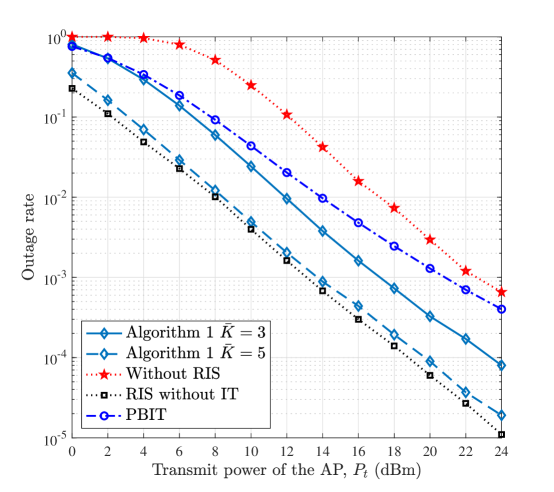
In Fig. 4, we consider the PBIT scheme where elements in are independently drawn from the set with equal probability. Under the PBIT scheme, the average number of ON-state groups at the RIS is . The outage rates of our proposed RIS-RPM scheme with and are plotted. Two benchmark schemes are considered: 1) Benchmark scheme without IT; 2) Conventional MISO scheme without RIS. Fig. 4 shows the outage rate performance of different schemes versus the AP’s transmit power, where , and m. We can observe that the outage rate performance of the proposed RIS-RPM scheme with outperforms that of the PBIT counterpart. This can be understood by the fact that different from the PBIT counterpart that suffers from large fluctuation in the reflected signal power due to the varying number of ON-state elements, the RIS-RPM scheme keeps the number of ON-state elements at each time constant to reduce such power fluctuation, thus showing better outage rate performance. Moreover, by increasing the number of ON-state groups , the outage rate performance of the RIS-RPM scheme can be further improved.
VI-C Achievable Rate Performance
To evaluate the achievable rate performance of the RIS-RPM scheme, the following schemes are considered: 1) Benchmark scheme without IT; 2) Conventional MISO scheme without RIS; 3) Upper bound that computes the achievable rate of (V-B2); 4) PBIT scheme where elements in are independently drawn from the set with equal probability. In the sequel, the active and passive beamforming vectors are obtained based on the estimated CSI.
VI-C1 Effect of AP-User Horizontal Distance
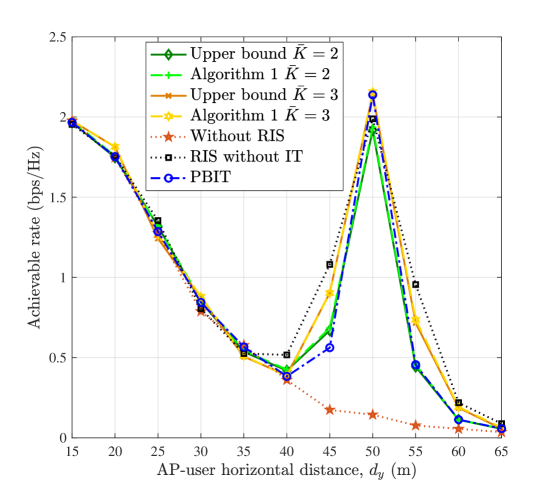
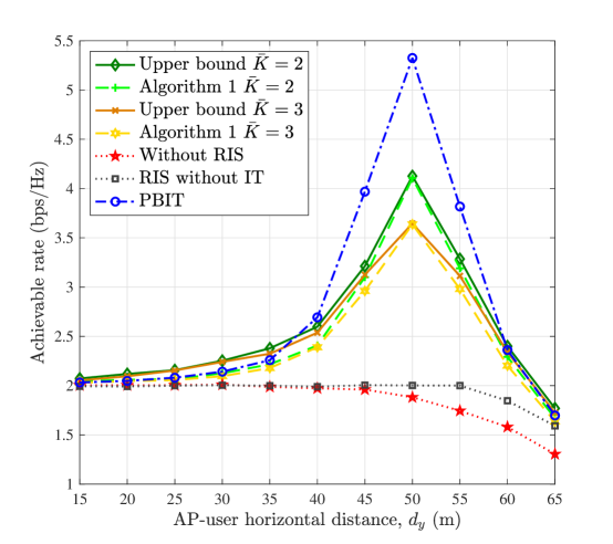
In Fig. 5, we evaluate the effect of on the achievable rate, where , and . One can observe from Fig. 5(a) that, when the transmit power of the AP is very low, the achievable rate of the scheme without RIS decreases as the user moves away from the AP, and approaches zero. In contrast, the achievable rates of those schemes assisted by the RIS increase drastically as the user moves toward the RIS, and decrease as the user moves away from both the AP and RIS. This is because when the user is close to either the AP or RIS, it is able to receive stronger transmitted/reflected signals from the AP/RIS. This phenomenon implies that the cell-edge user can benefit from an RIS deployed in its neighborhood, i.e., the rate of the cell-edge user can be enhanced by deploying an RIS, instead of improving the AP’s transmit power or deploying an expensive AP/relay. On the other hand, we observe from Fig. 5(a) that the RIS-RPM scheme with has the potential to outperform the one without IT despite that the received signal power achieved by the RIS-RPM scheme is lower than that achieved by the one without IT as shown in Fig. 3(b). For the RIS-RPM scheme with , since a large number of RIS elements are turned OFF deliberately for information transfer, the additional information from the RIS cannot compensate for the information reduction caused by the loss of received signal power, thus leading to a smaller achievable rate than the scheme without IT. Moreover, it can be observed from Fig. 5(b) that when the AP’s transmit power is high, the RIS-RPM scheme exhibits significantly superior rate performance over the scheme without IT, which is attributed to the additional information delivered by the RIS. This implies that the RIS-RPM scheme provides a mechanism to enable a flexible tradeoff between the received signal power and achievable rate performance by varying the number of OFF-state groups at the RIS. Moreover, when the transmit power of the AP is high, the PBIT scheme achieves the maximum achievable rate, as expected.
VI-C2 Effect of Number of ON-State RIS-elements Groups
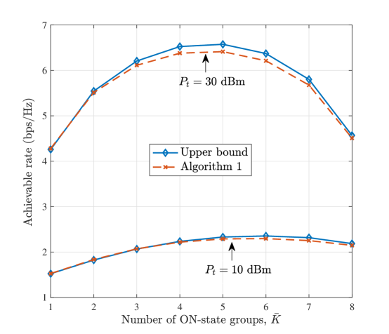
We compare the achievable rate of the RIS-RPM scheme versus in Fig. 6, where , m, and are considered. One can observe that there exists an optimal , which varies with different AP’s transmit power levels. For dBm, the optimal is 5 whereas the optimal for dBm is 6. Generally, it is expected that when the AP’s transmit power is high enough, the optimal is more likely to be , since the entropy of the RIS is maximized. Furthermore, when the AP’s transmit power is very high, due to the assumption of finite-alphabet input, the achievable rate at different values will be the sum of the corresponding uncoded transmitted information rates of the AP and RIS. In contrast, when the AP’s transmit power becomes very low, the optimal is more likely to be , since the reflected signal power is maximized while the RIS still can convey its information through RPM.
VI-C3 Effect of RIS-elements Grouping Ratio
Each group consists of elements with elements along -axis and elements along -axis.
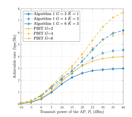
The RIS-elements grouping ratio is defined by . Let denote the ratio of time overhead for channel estimation to the coherence time normalized to the symbol sampling period. In Fig. 7, we examine the effect of on the achievable rate, where m, , and for the proposed RIS-RPM scheme. Note that the average number of ON-state RIS elements keeps constant for different schemes. As can be seen, the RIS-RPM scheme with large can achieve better achievable rate performance. This phenomenon can be explained by the fact that with large grouping ratio, not only the degrees of freedom for RIS reflection design increases, achieving high passive beamforming gain, but also more additional information can be conveyed through the index combination of RIS-elements groups, both improving the sum achievable rate. However, as shown in Table II, the pilot overhead ratio increases with the grouping ratio, which results in more time for channel estimation and less time for data transmission, thus reducing the average achievable rate. On the other hand, we can observe that a large AP’s transmit power level is needed for the PBIT scheme to be competitive.
VII Conclusions
In this paper, we considered an RIS-enhanced MISO wireless communication system and proposed the RPM scheme for the dual-use of passive beamforming and information transfer of the RIS. A practical beamforming design based on the RIS’s statistical ON/OFF state information was proposed to maximize the average received signal power at the user, for which an efficient algorithm based on the alternating optimization technique was proposed to obtain a high-quality solution. Next, we formulated an optimization problem to maximize the instantaneous received signal power by designing active and passive beamforming based on the RIS’s instantaneous ON/OFF state information, which characterized the upper bound on the received signal power of the RIS-RPM scheme. Moreover, the asymptotic outage probability of the RIS-RPM scheme over Rayleigh fading channels was derived in closed-form. In particular, the RIS was shown to be able to increase the diversity gain by properly designing the phase shifts of its elements. The achievable rate of the RIS-RPM scheme has been analyzed for the case where the transmitted symbol was drawn from a finite constellation. Finally, simulation results corroborated the effectiveness of Algorithm 1 as well as the RIS-RPM scheme and revealed the effect of different system parameters on the achievable rate performance of the RIS-RPM scheme. It was shown that the RIS-RPM scheme was able to improve the achievable rate performance despite the loss in received signal power as compared to the conventional RIS-assisted system with full-ON reflection.
References
- [1] F. Boccardi, R. W. Heath, A. Lozano, T. L. Marzetta, and P. Popovski, “Five disruptive technology directions for 5G,” IEEE Commun. Mag., vol. 52, no. 2, pp. 74–80, Feb. 2014.
- [2] F. Sohrabi and W. Yu, “Hybrid digital and analog beamforming design for large-scale antenna arrays,” IEEE J. Sel. Topics Signal Process., vol. 10, no. 3, pp. 501–513, Apr. 2016.
- [3] H. Q. Ngo, E. Larsson, and T. Marzetta, “Energy and spectral efficiency of very large multiuser MIMO systems,” IEEE Trans. Commun., vol. 61, no. 4, pp. 1436–1449, Apr. 2013.
- [4] F. Liu, A. Pitilakis, M. S. Mirmoosa, O. Tsilipakos, X. Wang, A. C. Tasolamprou, S. Abadal, A. Cabellos-Aparicio, E. Alarcón, C. Liaskos, N. V. Kantartzis, M. Kafesaki, E. N. Economou, C. M. Soukoulis, and S. Tretyakov, “Programmable metasurfaces: State of the art and prospects,” in Proc. IEEE ISCAS, Florence, Italy, May 2018, pp. 1–5.
- [5] T. J. Cui, M. Q. Qi, X. Wan, J. Zhao, and Q. Cheng, “Coding metamaterials, digital metamaterials and programmable metamaterials,” L. Sci. Appl., vol. 3, no. 10, pp. e218, Oct. 2014.
- [6] M. Di Renzo, A. Zappone, M. Debbah, M.-S. Alouini, C. Yuen, J. de Rosny, and S. Tretyakov, “Smart radio environments empowered by reconfigurable intelligent surfaces: How it works, state of research, and road ahead,” arXiv preprint arXiv:2004.09352, 2020.
- [7] X. Tan, Z. Sun, D. Koutsonikolas, and J. M. Jornet, “Enabling indoor mobile millimeter-wave networks based on smart reflect-arrays,” in Proc. IEEE INFOCOM, Hawaii, USA, Apr. 2018, pp. 270–278.
- [8] C. Liaskos, S. Nie, A. Tsioliaridou, A. Pitsillides, S. Ioannidis, and I. Akyildiz, “A new wireless communication paradigm through software-controlled metasurfaces,” IEEE Commun. Mag., vol. 56, no. 9, pp. 162–169, Sep. 2018.
- [9] E. Basar, M. Di Renzo, J. De Rosny, M. Debbah, M. Alouini, and R. Zhang, “Wireless communications through reconfigurable intelligent surfaces,” IEEE Access, vol. 7, pp. 116 753–116 773, 2019.
- [10] C. Huang, S. Hu, G. C. Alexandropoulos, A. Zappone, C. Yuen, R. Zhang, M. Di Renzo, and M. Debbah, “Holographic MIMO surfaces for 6G wireless networks: Opportunities, challenges, and trends,” IEEE Wireless Commun., to appear, 2020.
- [11] M. Di Renzo and J. Song, “Reflection probability in wireless networks with metasurface-coated environmental objects: An approach based on random spatial processes,” EURASIP J. Wireless Commun. Netw., no. 99, Apr. 2019.
- [12] N. S. Perović, M. Di Renzo, and M. F. Flanagan, “Channel capacity optimization using reconfigurable intelligent surfaces in indoor mmWave environments,” arXiv preprint arXiv:1910.14310, 2019.
- [13] Q. Wu and R. Zhang, “Towards smart and reconfigurable environment: Intelligent reflecting surface aided wireless network,” IEEE Commun. Mag., vol. 58, no. 1, pp. 106–112, Jan. 2020.
- [14] C. Huang, A. Zappone, G. C. Alexandropoulos, M. Debbah, and C. Yuen, “Reconfigurable intelligent surfaces for energy efficiency in wireless communication,” IEEE Trans. Wireless Commun., vol. 18, no. 8, pp. 4157–4170, Aug. 2019.
- [15] C. Huang, G. C. Alexandropoulos, A. Zappone, M. Debbah, and C. Yuen, “Energy efficient multi-user MISO communication using low resolution large intelligent surfaces,” in Proc. IEEE GLOBECOM, Abu Dhabi, UAE, Dec. 2018, pp. 1–6.
- [16] E. Björnson, Ö. Özdogan, and E. G. Larsson, “Intelligent reflecting surface versus decode-and-forward: How large surfaces are needed to beat relaying?” IEEE Wireless Commun. Lett., vol. 9, no. 2, pp. 244–248, Feb. 2020.
- [17] W. Tang, M. Z. Chen, X. Chen, J. Y. Dai, Y. Han, M. Di Renzo, Y. Zeng, S. Jin, Q. Cheng, and T. J. Cui, “Wireless communications with reconfigurable intelligent surface: Path loss modeling and experimental measurement,” arXiv preprint arXiv:1911.05326, 2019.
- [18] Q. Wu and R. Zhang, “Intelligent reflecting surface enhanced wireless network: Joint active and passive beamforming design,” in Proc. IEEE GLOBECOM, Abu Dhabi, United Arab Emirates, Dec. 2018, pp. 1–6.
- [19] A. Taha, M. Alrabeiah, and A. Alkhateeb, “Enabling large intelligent surfaces with compressive sensing and deep learning,” arXiv preprint arXiv:1904.10136, 2019.
- [20] G. C. Alexandropoulos and E. Vlachos, “A hardware architecture for reconfigurable intelligent surfaces with minimal active elements for explicit channel estimation,” in Proc. IEEE ICASSP, Barcelona, Spain, May 2020, pp. 9175–9179.
- [21] C. Huang, G. C. Alexandropoulos, C. Yuen, and M. Debbah, “Indoor signal focusing with deep learning designed reconfigurable intelligent surfaces,” in Proc. IEEE SPAWC, Cannes, France, Jul. 2019, pp. 1–5.
- [22] D. Mishra and H. Johansson, “Channel estimation and low-complexity beamforming design for passive intelligent surface assisted MISO wireless energy transfer,” in Proc. IEEE ICASSP, Brighton, United Kingdom, May 2019, pp. 4659–4663.
- [23] Z. He and X. Yuan, “Cascaded channel estimation for large intelligent metasurface assisted massive MIMO,” IEEE Wireless Commun. Lett., vol. 9, no. 2, pp. 210–214, Feb. 2020.
- [24] Y. Yang, B. Zheng, S. Zhang, and R. Zhang, “Intelligent reflecting surface meets OFDM: Protocol design and rate maximization,” IEEE Trans. Commun., early access, 2020.
- [25] B. Zheng and R. Zhang, “Intelligent reflecting surface-enhanced OFDM: Channel estimation and reflection optimization,” IEEE Wireless Commun. Lett., vol. 9, no. 4, pp. 518–522, Apr. 2020.
- [26] C. You, B. Zheng, and R. Zhang, “Intelligent reflecting surface with discrete phase shifts: Channel estimation and passive beamforming,” arXiv preprint arXiv:1911.03916, 2019.
- [27] T. L. Jensen and E. De Carvalho, “An optimal channel estimation scheme for intelligent reflecting surfaces based on a minimum variance unbiased estimator,” in Proc. IEEE ICASSP, Barcelona, Spain, May 2020, pp. 5000–5004.
- [28] L. Wei, C. Huang, G. C. Alexandropoulos, and C. Yuen, “Parallel factor decomposition channel estimation in RIS-assisted multi-user MISO communication,” in Proc. IEEE SAM, Hangzhou, China, Jun. 2020.
- [29] B. Zheng, C. You, and R. Zhang, “Intelligent reflecting surface assisted multi-user OFDMA: Channel estimation and training design,” arXiv preprint arXiv:2003.00648, 2020.
- [30] C. Huang, R. Mo, and C. Yuen, “Reconfigurable intelligent surface assisted multiuser MISO systems exploiting deep reinforcement learning,” IEEE J. Select. Areas Commun., early access, 2020.
- [31] E. Basar, “Large intelligent surface-based index modulation: A new beyond MIMO paradigm for 6G,” IEEE Trans. Commun., early access, 2020.
- [32] R. Karasik, O. Simeone, M. Di Renzo, and S. Shamai, “Beyond max-SNR: Joint encoding for reconfigurable intelligent surfaces,” arXiv preprint arXiv:1911.09443, 2019.
- [33] M. Di Renzo, M. Debbah, D.-T. Phan-Huy, A. Zappone, M.-S. Alouini, C. Yuen, V. Sciancalepore, G. C. Alexandropoulos, J. Hoydis, H. Gacanin, J. de Rosny, A. Bounceur, G. Lerosey, and M. Fink, “Smart radio environments empowered by reconfigurable AI meta-surfaces: An idea whose time has come,” EURASIP J. Wireless Commun. Netw., vol. 2019, no. 1, May 2019.
- [34] X. Yuan, Y.-J. Zhang, Y. Shi, W. Yan, and H. Liu, “Reconfigurable-intelligent-surface empowered 6G wireless communications: Challenges and opportunities,” arXiv preprint arXiv:2001.00364, 2020.
- [35] W. Yan, X. Yuan, and X. Kuai, “Passive beamforming and information transfer via large intelligent surface,” IEEE Wireless Commun. Lett., vol. 9, no. 4, pp. 533–537, Apr. 2020.
- [36] W. Yan, X. Yuan, Z.-Q. He, and X. Kuai, “Passive beamforming and information transfer design for reconfigurable intelligent surfaces aided multiuser MIMO systems,” arXiv preprint arXiv:1912.10209, 2019.
- [37] H. Yang, X. Chen, F. Yang, S. Xu, X. Cao, M. Li, and J. Gao, “Design of resistor-loaded reflectarray elements for both amplitude and phase control,” IEEE Antennas Wireless Propag. Lett., vol. 16, pp. 1159–1162, Nov. 2017.
- [38] A. Man-Cho, J. Zhang, and Y. Ye, “On approximating complex quadratic optimization problems via semidefinite programming relaxations,” Mathematical Programming, vol. 110, no. 1, pp. 93–110, Jun. 2007.
- [39] M. Grant and S. Boyd, “CVX: Matlab software for disciplined convex programming,” 2016. [Online]. Available: http://cvxr.com/cvx
- [40] Z.-Q. Luo, W.-K. Ma, A. M.-C. So, Y. Ye, and S. Zhang, “Semidefinite relaxation of quadratic optimization problems,” IEEE Signal Process. Mag., vol. 27, no. 3, pp. 20–34, May 2010.